Install and Configure VMS
![]() For supported software information, click here.
For supported software information, click here.
Versa Messaging Service (VMS) is a scalable, high-performance messaging service for streaming dynamic, high frequency, low latency data between Versa products (for example, Versa Operating System™ (VOS™), Versa Director, Versa Controller, Versa Concerto, and Versa Analytics) as well as between Versa products and third-party sources.
This article describes:
- VMS architecture, required interfaces, and how VMS works with Versa headend components.
- VMS deployment overview, including the hardware requirements for deploying VMS.
- Release-wise support of VMS services.
- How to install a VMS server.
- How to perform the initial configuration of the primary VMS server.
- How to perform the initial configuration of the secondary VMS server for high availability (HA).
- How to configure Versa Director for VMS to communicate with Versa headend and external components.
- How to configure the VMS messaging service for VOS devices to communicate with the VMS server and to enable VMS services.
- How to configure an application delivery controller (ADC) for HA.
- How to configure Analytics to receive syslogs from VMS.
VMS Architecture Overview
VMS uses a microservice architecture based on Kubernetes to deliver scalable, reliable applications. It delivers real-time messages from multiple external sources to VOS devices and to other Versa services and platforms.
VMS Interfaces
This section describes the interface requirements to deploy a VMS node.
When you deploy VMS, it is recommended that you configure the following interfaces:
- Northbound interface—Management interface to communicate and process information from external sources, such as third-party authentication from a WMI agent, a RADIUS accounting server, SCIM, XIP EIP, and threat feeds. VMS processes incoming data, normalizes and reformats it for delivery to subscribed VOS devices, other Versa components, and external connectors. For more information about the WMI agent, see Install and Configure the WMI Agent.
- Southbound interface—A gRPC connection that enables branches or gateways to subscribe or stream the data to and from VMS. This interface also forwards logs and exceptions to Versa Analytics nodes.
For the ports required on each interface, see VMS Firewall Requirements.
VMS also supports an elastic interface IP address (virtual IP address). This acts as a load balancer IP address for VMS and you must configure it in the same subnet to which internet or all external sources send data to the VMS (northbound is recommended).
The following figure shows the mapping of VMS interfaces:

VMS and Versa Headend Components
VMS works with the following Versa components:
- Concerto—User and group orchestration.
- Director—Tenant and service on-boarding in VMS clusters. You configure VMS using the Director UI.
- Analytics—Log service activities and alarms.
- Controller—Connection to VOS nodes.
- VOS devices—VOS devices establish long-term gRPC-based communication with VMS to send and receive streamed data.
VMS connects with other Versa headend components through the management plane. Versa Director uses the management plane to configure tenants and services on VMS, as well as configurations required to communicate with other Versa headend components such as Versa Analytics. To configure communication between VMS and Versa Director, you configure a VMS connector from the Director UI. For more information, see Configure a VMS Connector, below.
The VMS elastic interface interacts with external sources and agents, such as AAA servers, Kafka, Panorama, and the Versa WMI, which is connected to Active Directory (AD), to receive data.
The figure below illustrates the data workflow in VMS:

- VMS connects with multiple external sources through its elastic IP address, ensuring continuous event and log ingestion. The external sources include Active Directory services, threat Intelligence repositories, and Panorama, among others.
- Each VOS device subscribes to VMS for one or more services, such as SASE for SIM, third-party authentication, or XIP EIP, and receives streaming data. For more information about VMS services, see Support for VMS Services, below.
- External components and agents send data or stream logs to VMS.
- VMS processes the streamed data from external sources and converts it to a format that VOS devices can understand.
- VMS streams data to subscribed VOS devices and forwards logs and exceptions to Versa Analytics nodes. VMS can also send data or logs to external components.
This architecture highlights how VMS acts as a central broker, bridging external services with the Versa SD-WAN ecosystem for unified management and analytics. VOS devices subscribe to VMS for specific services and receive continuous data streams. External agents and components feed data or log streams to VMS through its elastic IP address.
To deploy high availability (HA) for the VMS server, it is recommended to install a standalone cluster in both the primary data center (DC) and disaster recovery (DR). Both VMS nodes have northbound connectivity through the elastic IP addresses using a firewall to ensure secure and continuous access for external agents, while southbound connectivity is established from the controllers to the SD-WAN overlay for hub and branch VOS devices. The following figure shows how HA works in VMS.

To manage the failover between the VMS servers on the primary datacenter and disaster recovery datacenter, you must install an ADC server on the southbound interface. VOS devices connect through the ADC virtual IP address that intelligently directs traffic to the active VMS node, ensuring seamless failover if the node becomes unavailable. This provides redundancy, uninterrupted management and control plane services, and secure communication with both external agents and SD-WAN endpoints.
VMS Deployment Overview
To deploy VMS, you install it as a node in the control plane. The control plane node initializes and manages the VMS cluster, including orchestration, configuration, and cluster health monitoring.
To deploy VMS, you do the following:
- Install the VMS software on a bare-metal platform. See Install VMS, below.
- Perform initial configuration of the VMS server from the shell of the bare-metal platform. See Configure a VMS Server Using Bash, below.
- (For high availability) Configure the secondary VMS server. See Configure the Secondary VMS Server for HA, below.
- Configure VMS from Versa Director. See Configure VMS from Versa Director, below.
- (For high availability) Configure an ADC Server on the Control network, which allows VOS devices to connect with the active VMS cluster. See Configure the ADC Service, below.
- Configure a VMS server profile for a VOS device to communicate with the VMS server. You can then enable VMS services to send or receive stream feeds. See Configure VMS Messaging Service, below.
VMS Hardware Requirements
This section describes the hardware requirements to deploy a VMS node.
It is recommended that you deploy VMS on physical servers. The following table provides the minimum requirements for a VMS node with 3 tenants and 2 services.
| Node Type | Control Plane Node |
|---|---|
|
CPU |
16 cores, no-hyperthreading |
|
Memory |
32 GB RAM |
|
Disk |
1 TB SSD (IOPS of 600 MBPS in mixed mode) |
|
Network IP Addresses |
3—If you require out-of-band management; otherwise 2. |
Support for VMS Services
The table below shows the VMS services and their support on VOS, Director, Analytics, and Concerto. Use the latest VMS, VOS, Director, Concerto, and Analytics releases for deployments that support all services. For more information, see Enable and Configure VMS Services.
VMS supports multitenancy. You can select multiple tenants and enable each of these services for these tenants from Versa Director.
| VMS Service Name | VOS | Director | Analytics | Concerto |
|---|---|---|---|---|
|
Third-party authentication |
Yes |
Yes |
Yes | NA |
|
XIP EIP |
Yes |
Yes | Yes | NA |
|
SASE for SIM |
Yes |
Yes | Yes | Yes For more information, see Configure SASE for SIM. |
|
VOS aggregator service |
Yes |
Yes | Yes | NA |
|
System cross-domain identity management (SCIM) |
Yes | Yes | Yes | Yes For more information, see Provision SCIM Service on Versa SASE. |
|
Versa user and entity behavior analytics (UEBA) |
Yes | Yes | Yes | Yes For more information, see Configure User and Entity Behavior Analytics (UEBA). |
| Threat Intelligence Note: The Threat Intelligence feature was partially provided by the VSync tool and is now provided by VMS, making VSync obsolete and incompatible with these Versa software versions. |
Yes | Yes For more information, see Configure Threat Intelligence from VMS. |
Yes | NA |
| Kafka MirrorMaker | Yes | Yes For more information, see Enable and Configure Kafka MirrorMaker. |
NA | Yes |
|
Versa Advanced Security Cloud (ASC) For more information, see Configure ASC Worker Nodes and Deploy Versa Secure Lens |
Yes | Yes | NA | NA |
|
Device Risk Score (DRS) For more information, see Configure VMS to Integrate EDR Platforms |
Yes | Yes | NA | NA |
Install VMS
To install the VMS software, you install the VMS ISO image on a bare-metal platform or on a VM. The VMS virtual machine image can be one of the following formats:
- Amazon Machine Image (AMI)—For AWS cloud deployments
- ISO image—For bare-metal platforms or manual VM installation
- OVA file—For VMware environments
- QCOW2 image—for KVM/QEMU-based hypervisors
Note that the screenshots in this section show VMS software installation on a bare-metal server (in this example, Supermicro server). The screens may differ based on the server you use.
Before you Begin
Before you start the installation:
- Verify the hardware requirements. See VMS Hardware Requirements, above.
- Obtain the VMS image:
- Download the appropriate VMS ISO, OVA, or QCOW2 file from the Versa Networks portal.
- Verify the checksum (MD5/SHA256) to ensure file integrity.
- Access the bare-metal server. Connect directly through the server console or Configure Intelligent Platform Management Interface (IPMI) for remote access and media mounting.
- Before you configure Ethernet interfaces for a VMS server, determine the management interface IP address, subnet, and gateway (for each VMS node):
- Northbound or management interface IP addresses and FQDN for communication to external feeds or sources: here, Eth0.
- Southbound interface IP address and FQDN (RPC channel to branches, VOS, and gateways to stream processed/updated data): Eth1, typically in the same southbound subnet as the Versa headend.
- Elastic interface IP address and FQDN (VMS uses this for feed subscription of different components): typically on the same subnet as Eth0.
- Obtain VMS certificates provided by public or private PKIs. You can use CA-signed (third-party) certificates or self-signed certificates.
- Certificates must have the FQDN or IP addresses of both northbound and elastic FQDN in the SAN fields.
- As a best practice, allocate domain names, FQDNs, or elastic FQDNs based on the number of VMSs or HA that you plan to use.
- Verify that the required firewall ports are open between VMS and other Versa components. For more information, see VMS Firewall Requirements.
- Ensure connectivity to DNS and mappings in DNS are reflected correctly along with the DNS servers.
- Ensure that NTP is synced across the VMS nodes.
Install the VMS Software
- Log in to the remote console.

- Click anywhere in the Remote Console Preview window to launch the remote console. If the Java SE Development Kit is installed on the server, you can launch the remote console from the development kit.

- Select Virtual Media > Virtual Storage.

- In the Virtual Storage window, select the CDROM & ISO tab. The device settings window displays.

- Click the Logical Drive Type field and select ISO File.
- Click Open Image, and then type the full path name of the software image. You can find the image at: https://versanetworks.app.box.com/s/d7jh1z6y3kaijd3yfwil0uxchr1w9ton/folder/256571398920
- Click Plug In.
- Click OK.
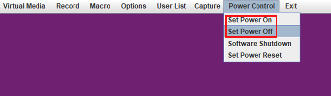
- Select the Power Control tab.
- To power down the device, select Set Power Off.
- To restart the device, select Set Power On.
- After the device restarts, the remote console window displays the server banner.

- To perform device setup, press the Delete key.
- In the Setup Utility window, select the Save and Exit tab.

- Click IPMI Virtual CDROM 3000 to run the ISO file from a local partition.
- Press Enter.
- Install the ISO image, and then configure the primary IP address and hostname. For example:
[admin@versa-Msgservice: -] $ sudo vi /etc network/interfaces
[sudo] password for admin:
[admin@versa-msgservice: -] $ sudo vi /etc/hosts
host.conf hostname hosts hosts.allow hosts.deny
[admin@versa-msgservice: -] $ sudo vi /etc/hosts
[admin@versa-msgservice: -] $ sudo vi /etc/hostname
sudo: unable to resolve host versa-msgservice: Resource temporarily unavailable
[admin@versa-msgservice: -] $ sudo reboot
After the reboot completes, VMS release information, including the version, release date, and package ID display. -
Check the status of the server by issuing the vsh status CLI command. Note that the command output may show the status of Kubelet as inactive. For example:
================================================================================
Versa Package Info: versa-msgservice-20251029-070135-541b9ea-5.2.2
================================================================================
Info: SYSTEM-SERVICES-STATUS
kubelet:activating
docker:active (3945)
vms-admin:inactive
vms-db:inactive
Configure the Primary VMS Server Using Bash
To configure the primary VMS server, you do the following:
- Configure Ethernet interfaces and a hostname on the VMS node. See Configure Ethernet Interfaces, below.
- Configure a name (DNS) server. See Configure Name Servers, below.
- Generate a self-signed database certificate. See Generate Self-Signed Database Certificate, below.
- Generate a certificate signing request (CSR):
- If you are using third-party certificates, import the CA-signed certificates. See Import Third-Party (CA-Signed) Certificates, below.
- If you are using self-signed certificates, generate self-signed certificates. See Generate Self-Signed Certificates, below.
- Perform the initial VMS server configuration, which does the following (see Configure the Primary VMS Server, below):
- Installs the Kubernetes control plane
- Creates a Docker overlay
- Loads containers
You perform the initial configuration from the shell of the VMS server.
The figure below describes the information flow for the following:
- Eth0 is the northbound or management interface.
- Eth1 is the southbound interface.
- Elastic interface to provide feed subscription of different components to VMS.
- Headend components such as Director, Analytics, and Controller nodes.

Configure Ethernet Interfaces
You configure the following Ethernet interfaces for a VMS server:
- Northbound or management interface IP addresses and FQDN for communication to external feeds or sources: here, Eth0.
- Southbound interface IP address and FQDN (RPC channel to branches, VoS, and gateways to stream processed/updated data): here, Eth1. This is typically in the same southbound subnet of the Versa headend.
You also configure the elastic interface IP address and FQDN, which VMS uses for feed subscription of different components. This is typically in the same subnet of Eth0 and this configuration is covered in Configure the Primary VMS Server, below.
To configure the Ethernet interfaces on the VMS servers, you edit the /etc/network/interfaces file. To edit this configuration file, you must have sudo privileges and update the file with appropriate interface details (in this example, eth0 and eth1) and assign the correct hostname. This configuration example uses the following interface details:
| Interface | IP Address | FQDN | Purpose |
|---|---|---|---|
|
eth0 |
10.73.18.9 |
vms-1.mvno.com |
Management |
|
eth1 |
172.17.9.2 |
vms-vos.mvno.com |
Communication with VOS |
|
Elastic |
10.73.18.253 |
vms01-elastic.mvno.com |
Communication with external agents |
To configure Ethernet interfaces:
- Log in to the primary VMS server.
- Edit the /etc/network/interfaces file using sudo for root privileges:
[admin@vms1: ~] $ sudo cat /etc/network/interfaces
[sudo] password for admin:
- Enter the password and edit the file to configure the interfaces (here, eth0 and eth1) and assign a hostname.
[admin@versa-msgservice: ~] $ sudo vi /etc/network/interfaces
[sudo] password for admin:
  # interfaces(5) file used by ifup(8) and ifdown(8)
  # Include files from /etc/network/interfaces.d:
  source-directory /etc/network/interfaces.d
auto eth0
iface eth0 inet static
    address 10.73.18.9
    netmask 255.255.0.0
    gateway 10.73.0.1
    dns-nameserver 10.75.0.53
    dns-nameserver 8.8.8.8

auto eth1
iface eth1 inet static
    address 172.17.9.2
    netmask 255.255.255.0
    mtu 1200
    post-up ip route add 192.168.0.0/16 via 172.17.9.1
For all the interfaces above, add host entries under the /etc/hosts file locally.
Configure Name Servers
You must add at least one name server (DNS server) for the microservices architecture (Kubernetes) to resolve external DNS and assign DNS names to services. If you do not configure a name server, errors can occur in microservices.
To add a name server:
- Issue the vsh add-name-servers CLI command.
- Enter the IP address of the name server. For example:
[root@admin-vms: db] $ vsh add-name-servers

================================================================================
Add Name Servers to the system
Input q/Q to quit anytime

================================================================================
Do you wish to configure name servers for the system? [y/N] : y
Input the number of Name Servers to add to the system : 1
Enter IP Address #1 : 10.75.0.53

Content of /etc/resolvconf/resolv.conf.d/base
nameserver 10.75.0.53
Generate Self-Signed Database Certificates
Communication between the application and the database occurs on the same host and requires a specific Common Name (CN) and Subject Alternative Name (SAN).
To generate a self-signed database certificate:
- Issue the vms_db_ca_cert_gen.sh command. Type the command on a single line, and replace all variables in italicized text with the appropriate values. Make sure to include the following:
- Valid email address
- Hardened password
- FQDN of the first control node of primary and backup clusters in the SAN field
[admin@versa-msgservice: ~] sudo /opt/versa/vms/db/vms_db_ca_cert_gen.sh --domain domain-name --country country
--state state --locality location --organization organization-name --organizationalunit unit-name
--email email-address --keypass password --validity validity --san san,DNS:dns-name
For example:[admin@versa-msgservice: ~] sudo /opt/versa/vms/db/vms_db_ca_cert_gen.sh --domain vms-1.mvno.com --country US --state CA --locality SC --organization mvno.com --organizationalunit IT --email admin@mvno.com --keypass password --validity 3650 --san vms-01.acme.com,DNS.1:vms-1.mvno.com,DNS.2:vms-2.mvno.com,DNS.3:vms-01-elastic.mvno.com, DNS.4:vms-02-elastic.mvno.com,DNS.5:vms-vos.mvno.com
Import Third-Party (CA-Signed) Certificates
Note that if you do not require certificates signed by a CA authority, you can skip this section and go to Generate Self-Signed Certificates, below.
If you use a third-party (CA-signed) certificate, follow the procedure in this section to generate a certificate signing request (CSR) and import the signed certificate back into the primary VMS server.
To generate the CSR:
- Issue the vsh generate-server-csr on the primary VMS server.
- Enter a minimum of 5 subject alternative names (SAN) and up to 7 when prompted. These represent the FQDNs or IP addresses where VMS services are consumed, including:
- Elastic interface of primary server (here, vms01-elastic.mvno.com)
- Management interface for VMS management access (here, vms-1.mvno.com)
- Elastic IP address for HA cluster (here, 10.73.18.253)
- Southbound Interface (here, vms-vos.mvno.com)
- (Optional) Secondary VMS HA interface (here, vms-2.mvno.com)
- (Optional) Secondary VMS southbound interface
- Elastic interface of secondary server (vms02-elastic.mvno.com)
- Enter the necessary certificate information when prompted. These include the following:
- Organization (O)
- Common Name (CN)
- Country
- Private key password—Save the private key password as you require this when you import the signed certificate.
- Enter a minimum of 5 subject alternative names (SAN) and up to 7 when prompted. These represent the FQDNs or IP addresses where VMS services are consumed, including:
The following is an example of output for the vsh generate-server-csr command. Descriptions of the highlighted text in the example output is provided in Step 2, below:
[admin@vms1: ~] $ vsh generate-server-csr

Disk Usage: 9%

    Are the entries for Subject Alt-Names finalized?

    Please Note that a minimum of atleast 5 FQDN/DNS/IP Address values are required for Subject Alt-Name Entry List for :

        1. Elastic
        2. Management
        3. HA-VIP
        4. SouthBound
        5. Secondary-HA(optional)
        6. Secondary VMS southbound interface (optional)
        7. Elastic-of-Secondary(optional)

    Insert [y/N] : y

    Input the number of Alternate Domain Name entries (minimum 1)to add to the Subject Alt-Names List : 5
    Input FQDN or DNS value #1 : vms-1.mvno.com
    Input FQDN or DNS value #2 : vms-vos.mvno.com
    Input FQDN or DNS value #3 : vms01-elastic.mvno.com
    Input FQDN or DNS value #4 : vms-2.mvno.com
    Input FQDN or DNS value #5 : vms02-elastic.mvno.com

    ** Please Note **

    There needs to be at least 4 entries for Subject Alt-Names including atleast 1 IP Address and 1 FQDN/DNS !!

    Input the number of IP Address entries (minimum 1) to add to the Subject Alt-Names List : 1
    Input IP Address value #1 : 10.73.18.9
    Copying server-csr-base.conf content into server-csr.conf

    Appending 'DNS.1 = vms-1.mvno.com' to server-csr.conf
    Appending 'DNS.2 = vms-vos.mvno.com' to server-csr.conf
    Appending 'DNS.3 = vms01-elastic.mvno.com' to server-csr.conf
    Appending 'DNS.4 = vms-2.mvno.com' to server-csr.conf
    Appending 'DNS.4 = vms02-elastic.mvno.com' to server-csr.conf
    Appending 'IP.1 = 10.73.18.253' to server-csr.conf

    Updated /opt/versa/scripts/certificates/server-csr.conf with the new Subject Alt-Names List

    Reading /opt/versa/scripts/certificates/server-csr.conf file :
    # --- no modifications required below ---
[ req ]
default_bits        = 2048
default_md          = sha256
prompt              = no
encrypt_key         = no
distinguished_name  = dn
req_extensions      = v3_req
default_keyfile     = /opt/versa/vms/certs/server-key.pem

[ dn ]
C = IN
O = Your Organization
CN = VMS Server

[ v3_req ]
# Extensions to add to a certificate request
basicConstraints = CA:FALSE
keyUsage = nonRepudiation, digitalSignature, keyEncipherment
subjectAltName = @alt_names

[ alt_names ]
DNS.1 = vms-1.mvno.com
DNS.2 = vms-vos.mvno.com
DNS.3 = vms01-elastic.mvno.com
DNS.4 = vms-2.mvno.com
IP.1 = 10.73.18.9

Domain is mandatory
Please Enter FQDN used in Versa Message Service: vms1.mvno.com
Application Certificate Credentials

Enter Password for Application Certificate      :
RE-Enter Password for Application Certificate   : Do you want to add more SAN's  ?  (y/N)   :  N

country, org, are all mandatory parameters

Please Enter the Country (2 characters only) where this server is located        : US
Please Enter the Organization which will use this VMS server is located          : mvno.com,
 => Generating Key and server CSR for request domain: example.com, key_pass      : password
 => Request details: [/C=US/O=Example Inc.,/CN=example.com]
 => Generating server csr with password encrypted keypass                        : password
 => Successfully generated Key file: /opt/versa/vms/certs/server-key.pem
 => Please copy the file out of the system and maintain it
 => Successfully generated SERVER CSR file: /opt/versa/vms/certs/server-csr.pem
 => Successfully generated the server CSR
 => Please copy the /opt/versa/vms/certs/server-key.pem out of this system and store it safely
 => Please use the Password "password" during server and client cert generation for \'vsh configure\'
- Enter the following information for the highlighted text shown in the sample output above:
- Please Enter FQDN used in Versa Message Service—Enter the FQDN that VOS devices use to consume VMS services.
- RE-Enter Password for Application Certificate: Do you want to add more SANs?—Enter Y to enter more SANs.
- Please Enter the Country (2 characters only) where this server is located—Country in mandatory for the certificate.
- Please Enter the Organization which will use this VMS server is located—Organization name is mandatory for the certificate.
- Generating Key and server CSR for request domain: example.com, key_pass—Password key displays here. Save this information carefully.
- Successfully generated SERVER CSR file—Displays the location on the VMS server where the CSR is saved (here, /opt/versa/vms/certs/server-csr.pem)
- Please copy the /opt/versa/vms/certs/server-key.pem out of this system and store it safely—Displays the location on the VMS server where the private key is saved. Store this safely.
- After you enter all the required information, the following files are generated:
- /opt/versa/vms/certs/server-key.pem (private key to save in a safe location)
- /opt/versa/vms/certs/server-csr.pem (CSR)
- Send the server-csr.pem file to a trusted CA for signing.
- After you receive the signed CSRs from the CA, copy them back to the VMS primary server nodes by issuing the vsh import-ca-certs command. When prompted, enter the private key password that you saved in Step 2, above. Note that if you have a secondary cluster, you do not have to generate CSR requests for both. You can generate a single CSR with the required SANs on the primary cluster and then import the certificates to both clusters using the vsh import-server-certs command.
Generate Self-Signed Certificates
If you are not using third party (CA-signed certificates) follow this procedure to generate self-signed certificates.
To generate self-signed certificates:
- Issuing the sudo /opt/versa/vms/certs/vms_cert_gen.sh command. Type the command on a single line. Replace all variables indicated in italicized text with the appropriate values. Note that domain name is mandatory.
[admin@versa-msgservice: ~] sudo /opt/versa/vms/certs/vms_cert_gen.sh --domain domain-name --country country
--state state --locality location --organization organization-name --organizationalunit unit-name
--email email-address --keypass password --validity validity --san san,DNS:dns-name
For example:[admin@versa-msgservice: ~] $ sudo /opt/versa/vms/certs/vms_cert_gen.sh Domain is mandatory Usage: vms_cert_gen Description: Generate private key and certificate signing request (CSR) for CA to sign Example: sudo /opt/versa/vms/certs/vms_cert_gen.sh --domain vms-1.mvno.com --country US --state CA --locality SC --organization mvno.com --organizationalunit IT --email admin@mvno.com --keypass password --validity 3650 --san vms-01.mvno.com,DNS.1:vms-1.mvno.com,DNS.2:vms-2.mvno.com,DNS.3:vms-01-elastic.mvno.com,DNS.4:vms-02-elastic.mvno.com,DNS.5:vms-vos.mvno.com Options: -h, --help Show this help message and exit. --domain <Fully qualified domain name> --country <Country name> --state <State name> --locality <Locality name> --organization <Organization name> --organizationalunit <Organizationalunit Name> --email <email> --keypass <private key password, if you want the private key is encrypted> [--validity] <certificate validity in days> [--san] <Fully qualified domain name for Subject Alt-Name, please refer to example for providing multiple values, DNS: DNS name; Each DNS value should not exceed 64 characters>
Success messages display on generating the key file and intermediate CSR file.
Configure the Primary VMS Server
To perform intial configuration of the primary VMS server:
- Issue the vsh configure CLI command to install the Kubernetes control plane, create a Docker overlay, and load containers.
- For the initial configuration, respond Y to the following prompt, and then enter the management IP address for VMS. Note that the management IP address is same as the IP address you use for eth0 (here, 10.73.18.9) For example:
====================================================================== First time configuration! ====================================================================== Is the primary interface configuration finalized? (y/N) : y Management Interface IP of this VMS server Please Enter this VMS Server Management/Primary Interface IP Address : 10.73.18.9 ====================================================================== - Respond Y to the following prompt ("Is the primary interface configuration finalized?") and enter the FQDN of the VMS server (here, vms-1.mvno.com). For example:
FQDN/Hostname of this VMS server
Is the hostname of this VMS server finalized?  (y/N) :  y
Please enter the Hostname of this VMS Server:  vms-1.mvno.com
This may take up to 10 minutes to complete initialization
-
In response to the prompt "Is this the 1st Control Plane Node of the cluster?", enter Y to complete the configuration. For example:
Adding new hosts entry.
VMS server configuration
Is this the 1st Control Plane Node of the cluster? (y/N) :  y
================================================================================
This may take up to 10 minutes to complete initialization
================================================================================
Info: Installing Kubernetes ...
Info: Creating auto completions for kubectl
Info: Disabling Swap ...
Info: Creating Docker overlay ....
disabled_plugins = []
imports = []
oom_score = 0
plugin_dir = ""
required_plugins = []
root = "/var/lib/containerd"
state = "/run/containerd"
temp = ""
version = 2
Note: The installation takes approximately 10 minutes. Ensure that the SSH timeout from shell is set to more than 30 minutes to avoid installation failure.
When the Kubernetes control plane initializes, the success message displays. For example:
flannel/flannel                               v0.22.3    e23f7ca36333   2 years ago    70.2MB
localhost:5000/docker.io/flannel/flannel      v0.22.3    e23f7ca36333   2 years ago    70.2MB
localhost:5000/kube-apiserver                 v1.28.2    cdcab12b2dd1   2 years ago    126MB
registry.k8s.io/kube-apiserver                v1.28.2    cdcab12b2dd1   2 years ago    126MB
localhost:5000/kube-scheduler                 v1.28.2    7a5d9d67a13f   2 years ago    60.1MB
registry.k8s.io/kube-scheduler                v1.28.2    7a5d9d67a13f   2 years ago    60.1MB
localhost:5000/kube-proxy                     v1.28.2    c120fed2beb8   2 years ago    73.1MB
registry.k8s.io/kube-proxy                    v1.28.2    c120fed2beb8   2 years ago    73.1MB
localhost:5000/kube-controller-manager        v1.28.2    55f13c92defb   2 years ago    122MB
registry.k8s.io/kube-controller-manager       v1.28.2    55f13c92defb   2 years ago    122MB
quay.io/metallb/speaker                       v0.13.11   85ceeb6abfc8   2 years ago    113MB
localhost:5000/quay.io/metallb/speaker        v0.13.11   85ceeb6abfc8   2 years ago    113MB
localhost:5000/quay.io/metallb/controller     v0.13.11   92af1d17d1d6   2 years ago    63.2MB
quay.io/metallb/controller                    v0.13.11   92af1d17d1d6   2 years ago    63.2MB
flannel/flannel-cni-plugin                    v1.2.0     a55d1bad692b   2 years ago    8.04MB
localhost:5000/docker.io/flannel/flannel-cni-plugin v1.2.0 a55d1bad692b 2 years ago    8.04MB
localhost:5000/etcd                           3.5.9-0    73deb9a3f702   2 years ago    294MB
registry.k8s.io/etcd                          3.5.9-0    73deb9a3f702   2 years ago    294MB
localhost:5000/coredns                        v1.10.1    ead0a4a53df8   2 years ago    53.6MB
registry.k8s.io/coredns/coredns               v1.10.1    ead0a4a53df8   2 years ago    53.6MB
localhost:5000/pause                          3.9        e6f181688397   3 years ago    744kB
registry.k8s.io/pause                         3.9        e6f181688397   3 years ago    744kB
registry                                      2          2d4f4b5309b1   5 years ago    26.2MB
localhost:5000/docker.io/library/alpine       3.6        43773d1dba76   6 years ago    4.03MB
alpine                                        3.6        43773d1dba76   6 years ago    4.03MB

Initializing Kubernetes; this will take a few mins
SERVER-FQDN=vms-1.mvno.com
Docker_repo_location=localhost
Kube Init successful
namespace/kube-flannel unchanged
clusterrole.rbac.authorization.k8s.io/flannel unchanged
clusterrolebinding.rbac.authorization.k8s.io/flannel unchanged
serviceaccount/flannel unchanged
configmap/kube-flannel-cfg unchanged
daemonset.apps/kube-flannel-ds unchanged
error: node vms-1.mvno.com already has node-role.kubernetes.io/control-plane taint(s) with same effect(s) and --overwrite is false
node/vms-1.mvno.com untainted
Tue Oct 28 16:51:16 PDT 2025:  Running recreate_flannel_run_dir completed
Kubernetes STIGs were applied successfully
- Issue the vsh configure CLI command again to configure the VMS control plane parameters. Here, you provide the elastic interface IP address, FQDN, or DNS (here, FQDN). For self-signed certificates, this command generates the server certificate, which is used by all external devices, agents, or Versa components to communicate with VMS. In a self-signed certificate, this certificate is signed by root-CA. In a CA-signed certificate, it is assumed that the previously imported root-CA has signed all the server and client certs.
- Configure the FQDN of the VMS server to generate and validate certificates (here, vms-1.mvno.com).
- Provide the FQDN for the elastic IP address of the node in the subject alternative name (SAN) of the certificates (here, vms-01-elastic.mvno.com). Agents use this FQDN to connect to VMS.
- Enter the SANs to be secured by the certificate. For HA, you require multiple SANs to have more than three FQDN names. For example:
=====================================================================
Initial Cluster Install is completed, configuring VMS Control Plane parameters
Configuring the Node for DNS/FQDN: vms-1.mvno.com
=====================================================================

============================CONFIGURING-COMMON-PARAMETERS============================

Please provide the below information; typed response will not be displayed

=====================================================================
VMS Server-Client Certificate Generation
Please provide the below information for the VMS node
This information is needed for Client Certificate Generation and Validation
Please include floating/elastic IP/FQDN/DNS entry as one of the SAN entries
When prompted, please enter the password used for root/intermediate certificate generation
=====================================================================

FQDN of Versa Message Service's
Please Enter FQDN used in Versa Message Service                                : vms-1.mvno.com

Please Enter Subject ALT Name 1 used in Versa Message Service certificate file : vms-01-elastic.mvno.com

Please Enter Subject ALT Name 2 used in Versa Message Service certificate file : vms-vos.mvno.com


Configuration file /opt/versa/scripts/certificates/server-csr.conf
    Please check/add FQDN entries
Do you want to continue with vms-1.mvno.com as the entry? (y/N) : y
- Respond Y to the prompt, "Do you want to continue with vms-1.mvno.com as the entry?" to confirm the FQDN, and then respond Y to the prompt "Do you want to generate the certificates with FQDN: vms-1.mvno.com?". This regenerates the certificates. For example:
Configuration file /opt/versa/scripts/certificates/server-csr.conf
    Please check/add FQDN entries
Do you want to continue with vms-1.mvno.com as the entry ? (y/N) : y

Certificate Regeneration
Existing Certificates FQDN:
Do you want to generate the certificates with FQDN: vms-1.mvno.com ? (y/N) : y
[2025-10-28 17:00:40-07:00]: Started generating certificates...
[2025-10-28 17:00:40-07:00]: Server private key and csr created successfully
[2025-10-28 17:00:40-07:00]: Creating server certificate...
[2025-10-28 17:00:40-07:00]: Server certificate created successfully
[2025-10-28 17:00:40-07:00]: Server certificate bundle created successfully
[2025-10-28 17:00:42-07:00]: Creating client private key and csr...
[2025-10-28 17:00:42-07:00]: Client private key and csr created successfully
[2025-10-28 17:00:42-07:00]: Creating client certificate...
[2025-10-28 17:00:42-07:00]: Client certificate created successfully
[2025-10-28 17:00:42-07:00]: Creating client certificate (pfx format)...
[2025-10-28 17:00:42-07:00]: Client certificate (pfx format) created successfully

[2025-10-28 17:00:42-07:00]: All certificates and keys are successfully created.
[2025-10-28 17:00:42-07:00]: Validating CA certificate...
/opt/versa/vms/certs/ca-cert.pem: OK
[2025-10-28 17:00:42-07:00]: Validation for CA certificate succeeded
[2025-10-28 17:00:42-07:00]: Validating server certificate...
/opt/versa/vms/certs/server-cert.pem: OK
[2025-10-28 17:00:42-07:00]: Validation for server certificate succeeded
[2025-10-28 17:00:42-07:00]: Validating client certificate...
/opt/versa/vms/certs/client-cert.pem: OK
[2025-10-28 17:00:42-07:00]: Validation for client certificate succeeded
[2025-10-28 17:00:42-07:00]: Exiting...

Certificate Regenerated with SAN: vms-1.mvno.com, vms-01-elastic.mvno.com, vms-vos.mvno.com
=====================================================================
Note that the prompts for the following steps appear together on the prompt, but are shown as separate steps here.
- Enter a unique name for the VMS node for server identification (here, vms-1.mvno.com). This is required for HA fail-over. For example:
Please provide the below server identification information
This Information is needed for HA fail-over
Please Enter a unique name for this VMS node  : vms-1.mvno.com
- Enter the application certificate keystore password and confirm the password. For example:
Application Certificate KeyStore Credentials
Enter Password for Application Certificate KeyStore    :
RE-Enter Password for Application Certificate KeyStore : secret/default-server-secret created
- Enter the IP address (here, 172.17.9.2) of the VMS host to which the VOS devices or ADC connect. You use the same IP address while configuring an ADC load balancer server in Configure an ADC Load Balancer Server, below. For example:
IP Address of VMS-Cluster where VOS/ADC will connect Please Enter IP Address for this VMS Cluster where VOS/ADC will connect : 172.17.9.2 - Next you configure the elastic interface FQDN and IP address of the VMS cluster for applications to connect and for agents send traffic respectively.
- Enter the elastic FQDN (here, vms-01-elastic.mvno.com) of VMS cluster to which applications connect. Note that this FQDN from SAN must be included in the server certificates. For example:
FQDN of VMS-Cluster where applications will connect (ELASTIC/Floating FQDN/hostname)
** This FQDN must exist in Server Certificates
Please Enter FQDN used as Entry for applications   : vms-01-elastic.mvno.com
- Enter the elastic IP address (here, 10.73.18.253) of the VMS cluster to which agents send traffic. The elastic IP address is a public-facing load balancer IP address of VMS and it must be in the same subnet as your internet-facing interface. When multiple nodes are added to the VMS cluster, the VMS load balancer uses VRRP to elect the leader to attract traffic. This IP address must be reachable from the internet. The elastic IP address is not assigned to any VMS node, the FQDN associated with this IP address is different from the VMS FQDN, and you cannot change this IP address after the configuration. For example:
Elastic Floating IP of this VMS Cluster where agents will send traffic to VMS Cluster
The FQDN associated with this IP is separate from VMS FQDN. This is a floating IP not assigned to any VMS node
This IP cannot be changed after configuration
Is the Elastic IP of this VMS Cluster finalized? (y/N) :  y
Please enter the Elastic IP of this VMS Server: 10.73.18.253
Updating existing hosts entry.
- Enter the elastic FQDN (here, vms-01-elastic.mvno.com) of VMS cluster to which applications connect. Note that this FQDN from SAN must be included in the server certificates. For example:
The certificate information displays after the certificate regenerates and adds new host entries. The following example output shows some of the information that displays:
Adding new hosts entry.

Info: Installing MetalLB Controller, speaker ...
namespace/metallb-system created
customresourcedefinition.apiextensions.k8s.io/addresspools.metallb.io created
customresourcedefinition.apiextensions.k8s.io/bfdprofiles.metallb.io created
customresourcedefinition.apiextensions.k8s.io/bgpadvertisements.metallb.io created
customresourcedefinition.apiextensions.k8s.io/bgppeers.metallb.io created
customresourcedefinition.apiextensions.k8s.io/communities.metallb.io created
customresourcedefinition.apiextensions.k8s.io/ipaddresspools.metallb.io created
customresourcedefinition.apiextensions.k8s.io/l2advertisements.metallb.io created
serviceaccount/controller created
serviceaccount/speaker created
role.rbac.authorization.k8s.io/controller created
role.rbac.authorization.k8s.io/pod-lister created
clusterrole.rbac.authorization.k8s.io/metallb-system:controller created
clusterrole.rbac.authorization.k8s.io/metallb-system:speaker created
rolebinding.rbac.authorization.k8s.io/controller created
rolebinding.rbac.authorization.k8s.io/pod-lister created
clusterrolebinding.rbac.authorization.k8s.io/metallb-system:controller created
clusterrolebinding.rbac.authorization.k8s.io/metallb-system:speaker created
configmap/metallb-excludel2 created
secret/webhook-server-cert created
service/webhook-service created
deployment.apps/controller created
daemonset.apps/speaker created
validatingwebhookconfiguration.admissionregistration.k8s.io/metallb-webhook-configuration created
Waiting for MetalLB initial bring-up..
- To verify the VMS primary server or node configuration, run the vsh status CLI command and check the if status of the services are running. For example:
[admin@versa-msgservice: ~] $ vsh status
[sudo] password for admin:
Disk Usage: 3%

===============================================================
Versa Package Info: versa-msgservice-20251029-070135-541b9ea-5.2.2
===============================================================

Info: SYSTEM-SERVICES-STATUS

kubelet                      is Running
docker                       is Running
containerd                   is Running
vms-db                       is Running
vms-admin                    is Running

===============================================================
- Copy the following server certificates from the /var/tmp/copy_certs/ directory to the first VMS node. After you have copied the certificates, you can configure VMS on Versa Director as described in Configure VMS from Versa Director, below.
- root-ca-cert.pem—This is the VMS root certificate. Upload it to the Files and Folders directory on the Director node and then associate it with a configuration template. VOS devices use this certificate to configure the VMS server.
- server-cert.pem—Upload this certificate to the Director node when you configure the VMS connector for TLS. The Director node validates the VMS certificate.
Configure the Secondary VMS Server for HA
This section describes how to configure a secondary VMS server for HA. You can use third-party certificates or self-signed certificates (generated when you configure the primary VMS server) on the secondary VMS server.
To configure the secondary VMS server:
- Generate self-signed database certificates. For more information, see Generate Self-Signed Database Certificates, above.
- Import the required certificates from the primary VMS server. When you Configure the Primary VMS Server, the generated certificates are stored in the /opt/versa/vms/certs folder. Copy the certificates from this directory on the primary VMS server (first VMS node) to the secondary VMS server (secondary VMS node). Note that the same client certificates are used on both VMS nodes because the WMI agent imports only one client certificate and uses this certificate for secure communication between the WMI agent to each of the VMS nodes.
- To import a third-party (CA-signed) certificate, issue the vsh import-ca-certs CLI command. For more information about generating a third-party CSR and importing it to the VMS cluster, see Import Third-Party (CA-Signed) Certificates, above.
- To import a self-signed certificate, issue the vsh import-server-certs CLI command. For more information about self-signed certificates, see Generate Self-Signed Certificates, above.
- When prompted, enter the private key password that you saved while generating certificates.
- After importing the certificates, to configure the secondary VMS server or node for HA, repeat the steps in Configure the Primary VMS Server on the secondary VMS server with the required changes in values, such as IP addresses and FQDN.
Configure VMS from Versa Director
To configure VMS from VMS Director, you do the following:
- Configure a VMS connector on a Director node. For more information, see Configure a VMS Connector, below.
- Perform tenant onboarding related to VMS from Concerto.
- Add the required certificates on Director and upload them to VOS.
You configure VMS for Versa Analytics for logs related to entitlement, debugging, and exceptions. Versa Analytics analyzes these logs and events, and generates reports and analytics for events shared by VMS. VOS connects to VMS using an ADC and VMS connects to Analytics through a controller. For more information, see Configure the ADC Service, below.
To configure VMS from a Director node, you create a VMS connector. While you can configure VMS from either the primary or secondary Director node, it is recommended that you configure the first control plane node from the primary Director node.
As part of configuring the VMS connector, you select the VMS interfaces that connects to your VOS devices and to which external agents connect; specify the Analytics controller node to which to send logs. You can also configure services such as third-party authentication, XIP EIP, SASE-for-SIM (Kafka and RADIUS), (for Releases 5.2.1 and later) system cross-domain identity management (SCIM), VOS aggregator, and user and entity behavior analytics (UEBA) for tenants.
Configure a VMS Connector
You use the VMS connector configuration wizard to configure and establish the initial connection to the VMS cluster on the first node of the VMS cluster.
To configure a VMS connector:
- In Director view, select the Administration tab in the top menu bar.
- Select Connectors > VMS in the left menu bar.
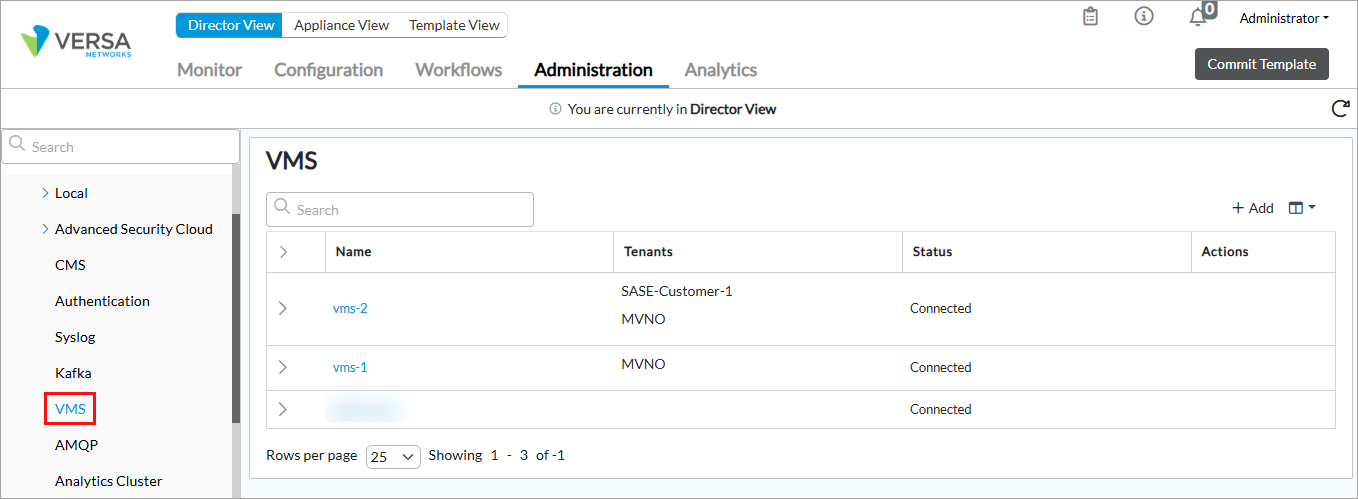
- Click + Add. The Configure VMS Connection configuration wizard displays.
- In workflow step 1, VMS Connection, enter information for the following fields.
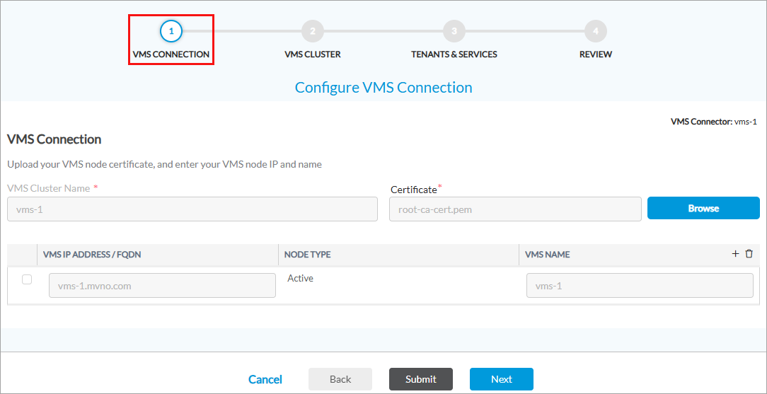
Field Description VMS Connector Name Enter a name for the VMS connector. Certificate Click Browse, and then upload the server certificate that you generated on the first VMS control plane node (here, root-ca-cert.pem) in Configure the Primary VMS Server, above, and saved in the /var/tmp/ folder. The file containing the server certificate must be in PEM format. VMS IP Address/FQDN (Table) Click the + Add icon to enter information about the VMS node. You must add at least one VMS address. - VMS IP Address/FQDN
Enter the IP address or FQDN of the VMS node. The value that you enter must be present as the subject alternative name (SAN) of the VMS node. - Node Type
Select the VMS node type:
- Control Node
- Worker Node
- VMS Name
Enter a name for the VMS node. - Click Next to go to workflow step 2, VMS Cluster, and then enter information for the following fields.
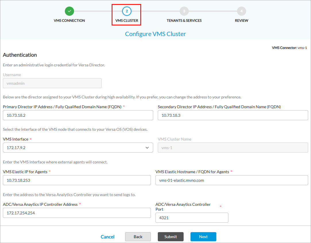
Field Description Username By default, the username vmsadmin displays. When you add the first VMS on a Director node, configure the credentials by entering the password and then confirm the password. Primary Director IP Address/Fully Qualified Domain Name Enter the primary IP address or FQDN of the Director node to which you have logged in. Secondary Director IP Address/Fully Qualified Domain Name Enter the secondary IP address or FQDN of the Director node. VMS Interface Select the VMS interface to use to communicate with VOS devices. VMS Cluster Name Enter a name for the VMS cluster. VMS HA uses the name to identify the cluster. VMS Elastic IP for Agents Enter the IP address that external agents, such as Kafka Broker, Kafka Consumer Topic, Kafka Producer, and the RADIUS accounting server, use to communicate with VMS. This IP address is also called the elastic or floating IP address, and it is assigned to the VMS cluster. The VMS load balancer, which is initiated on the first node in the cluster when the cluster is installed, attracts traffic intended for this IP address (or for a contiguous range of IP addresses) and forwards the traffic to the microservice that serves this traffic. You associate the floating IP address with an FQDN, and this FQDN must have a SAN entry in the VMS server certificate. Note that the elastic or floating IP must be associated with an IP address in the same subnet address space as the subnet of the network interfaces that are connected to the agent. VMS Elastic Hostname/FQDN for Agents Enter the VMS FQDN or hostname that external agents use to communicate with VMS. ADC/Versa Analytics IP Controller Address Enter the IP address of the Controller node to which to send syslog messages from VMS to Analytics node. VMS sends syslog messages for all start, stop, and exception events to Analytics nodes. ADC/Versa Analytics Controller Port Enter the Controller node port number to which to send syslog messages from VMS to Analytics nodes. - Click Next to go to workflow step 3, Tenants and Services. The following screen displays.

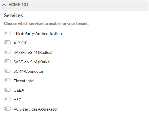
- Select the tenants for which you want to enable VMS services. You can select multiple tenants and enable services for each of these tenants. The selected tenants display in the Tenant Selected pane. For example, the following example screenshot displays multiple selected tenants. Note that you must enable at least one service for each tenant and configure its required fields to proceed from this screen.

- To enable services for a tenant, click the down arrow to display the available service options, and then slide the toggle to enable a service. For more information, see Enable and Configure VMS Services.
When you select a service, the fields associated with the service display. For example:

- Click Next to go to workflow step 4, Review.

- Review the information in all the sections. To make changes, click the
 Edit icon.
 - Click Submit.
Configure VMS for VOS Communication
You configure the VMS messaging service for your VOS device to communicate with the VMS server and to enable VMS services to send and receive stream feeds.
To configure the VMS messaging service, you do the following:
- Configure a messaging server profile for the VOS device to communicate with the VMS.
- Use the server profile to enable VMS services to send and receive stream feeds from the VMS server.
Configure a Messaging Server Profile
You configure a messaging server profile for the VOS device to communicate with the VMS server.
To add a messaging server profile:
- In Director view:
- Select the Administration tab in the top menu bar.
- Select the Appliances in the left menu bar.
- Select a device name in the main panel. The view changes to Appliance view.
- Select the Configuration tab in the top menu bar.
- Select Others > Organization > Messaging Service > Server Profile in the left menu bar.

- Click the + Add icon. In the Add Messaging Service Server popup window, enter information for the following fields.

Field Description Name
(Required)
Enter a name for the messaging server.
Value: Text string from 1 through 127 characters
Default: None
Description Enter a text description for the VMS messaging server. Routing Instance (Required) Select the routing instance through which the VMS messaging server is reachable. CA Chain (Required) Select the certificate authority (CA) chain to use for the server. This adds the certificate file in Versa Director. Port Enter the port number for the VMS messaging server.
Default: 1376
Address
- FQDN
Enter the fully qualified domain name of the messaging server. - Click OK.
Enable Stream Feeds for VMS Services
You enable VMS services to receive streaming feeds from the VMS server. To do this, associate a messaging server profile with the services that you configured in Configure a VMS Connector, above.
To enable a VMS service to send or receive streaming feeds:
- In Director view:
- Select the Administration tab in the top menu bar.
- Select an Appliance in the left menu bar.
- Select a device name in the main panel. The view changes to Appliance view.
- Select the Configuration tab in the top menu bar.
- Select Others > Organization > Messaging Service > VMS Service in the left menu bar.

- Click the
Edit icon next to a service. The Edit Service-Name VMS Service (here, Edit SASE-on-SIM VMS Service) popup window displays.
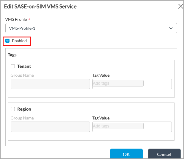
- In the VMS Profile field, select a VMS server profile. For more information, see Configure a Messaging Server Profile, above.
- Click Enabled to enable the service.
- (Optional) Under Tags, click Tenant and Region to enter tags for tenant and region groups. Note that threat intelligence windows do not display the Tag section.
- Click OK.
- Repeat Steps 4 to 8 for each service for which you want to enable stream feeds.
Configure the ADC Service
This section describes how to configure the application delivery controller (ADC) service on a VOS device. When you deploy VMS in an HA setup, it is essential to configure the ADC service in case of a VMS node failover. The VOS software establishes an active RPC connection with only one VMS node at a time. The ADC is responsible for continuously monitoring both VMS nodes and dynamically determines which node must be active. ADC on a controller has monitor probes to check if the VMS server is reachable and the selection of active VMS or switchover takes place based on this probing. For more information, see Configure an Application Delivery Controller.
The diagram below shows the flow of information between ADC (on controllers), VOS, and Analytics:

Secure SD-WAN CPEs connect to VMS servers through an ADC load balancer that is hosted in front of the VMS servers. You can use any load balancer for this function, including a VOS device. If you use a VOS device, you perform the following to configure ADC:
- Configure a tunnel virtual interface (TVI) on the device where you configure ADC.
- Enable ADC service for the device.
- Configure ADC health monitors.
- Configure ADC load balancer servers and the associate health monitors.
- Configure ADC load balancer server pools.
- Configure ADC virtual services.
Configure a Tunnel Virtual Interface
Configure a TVI on the device where you configure ADC. This helps to have to configure a common VIP IP address or FQDN on all VOS or gateway devices acting as a gRPC client. It is also beneficial when there are multiple Controllers with the same ADC configuration.
To configure a TVI:
- In Director view:
- Select the Administration tab in the top menu bar.
- Select the Appliances in the left menu bar.
- Select a device name in the main panel. The view changes to Appliance view.
- Select the Configuration tab in the top menu bar.
- Select Networking > Interfaces in the left menu bar.
- Select the Tunnel tab in the horizontal menu bar.

- Click the + Add icon, or select an existing tunnel interface. In Add/Edit Tunnel Interface popup window, enter the following information.

- Enter an interface number and unit (here, 0/8254).
- In the Subinterfaces table, click the unit (here, 0), and then enter the IP address of the virtual service (here, 172.17.254.254/32). You use this IP address when you configure an ADC virtual service in Configure an ADC Virtual Service, below. This virtual service IP address can belong to an FQDN if your enterprise has an internal DNS to resolve the IP address. Otherwise, you can use this IP address while configuring VMS on VOS using Versa Director.
- For information about configuring other parameters, see Configure Interfaces.
- Click OK.
- Select Networking > Virtual Routers in the left menu bar.

- Select the LAN VR of the organization (here, MVNO-Control-VR). The Edit LAN-VR popup window displays.

- Select the Virtual Router Details tab.
- In the Interfaces/Networks table, select the tunnel interface you added in Step 5 (here, tvi-0/8254.0).
- Click OK.
Enable ADC Service
Before you configure ADC services, you must enable an ADC on the VOS device. To do this, you enable the ADC globally in the service node group used by the VOS device.
To enable the ADC globally for a VOS device:
- Select the Configuration tab in the top menu bar.
- Select Others > Service Nodes > Service Node Groups in the left menu bar.
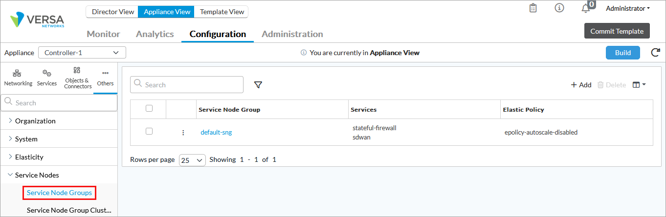
- Select the service node group, here default-sng. The Edit Service Node Group popup window displays.

- In the Services table, click ADC in the Available Services section to move it to Selected Services.
- Click OK.
- Select Others > Organization > Limits in the left menu bar.
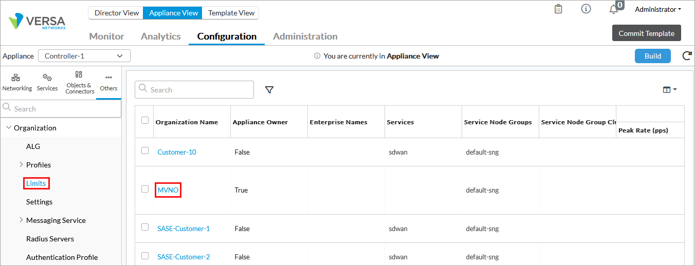
- Select the organization (here, MVNO). The Edit Organization Limit popup window displays.
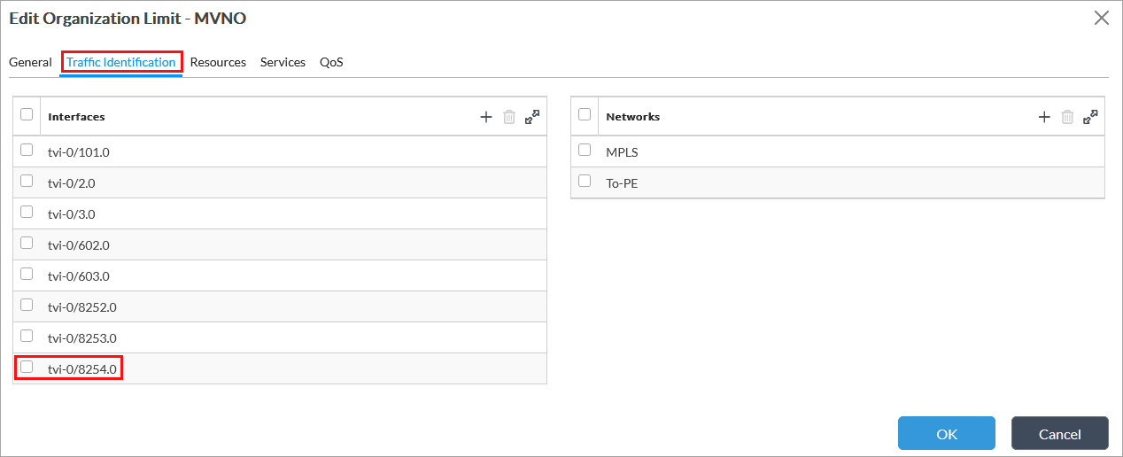
- Select the Traffic Identification tab.
- Select the interface you created in Step 5 of Configure a Tunnel Virtual Interface, above (here, tvi-0/8254.0).
- Select the Services tab.

- In the Services table, click + and select ADC from the drop-down.
- Click OK.
Configure an ADC Monitor
You configure ADC health monitors to run a probe between ADC and the VMS server to check if the VMS server is active and reachable.
To configure an ADC monitor:
- Select the Configuration tab in the top menu bar.
- Select Services > ADC > Monitors in the left menu bar.

- Click the + Add icon. In the Add Monitor popup window, enter the following information. (The screenshot here shows Edit Monitor popup window.)

- Enter the name of the monitor (here, VMS1).
- In the Types field, select ICMP or TCP.
- Click OK.
- Repeat Steps 3 through 6 to create another monitor (here, VMS2).
Configure an ADC Load Balancer Server
- Select Services > ADC > Local Load Balancers > Server in the left menu bar.

- Click the + Add icon. In the Add Server popup window, enter the following information. (The screenshot here shows the Edit Server popup window).
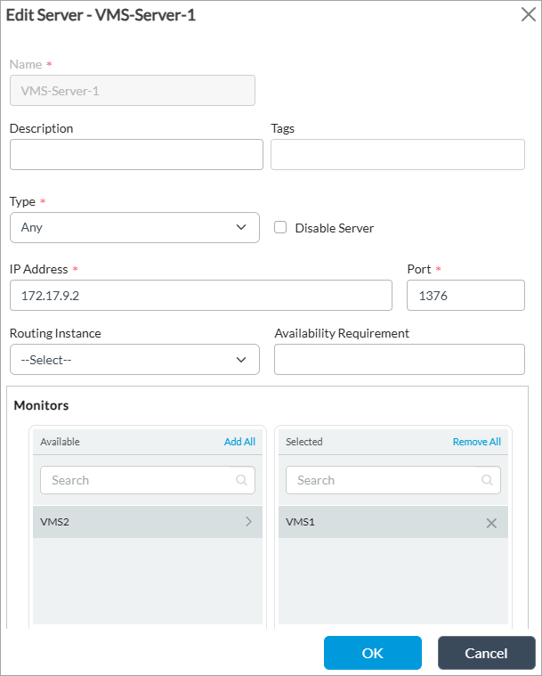
- Enter a name for the server (here, VMS-Server-1).
- Enter the IP address of the southbound interface of the primary VMS server which is reachable over control VR (here, 172.17.9.2).
- Enter port number 1376.
- In the Monitors table, click on the monitor in the Available list. This is the monitor that was added in Configure an ADC Monitor, above (here, VMS1). The monitor moves to the Selected list.
- For information about configuring other parameters, see Configure ADC Servers.
- Click OK.
- To add a backup VMS server, click the + Add icon again. In the Add Server popup window, enter the following information.

- Enter a name for the monitor (here, VMS-Server-2).
- Enter the IP address of the southbound interface of the primary VMS server which is reachable over control VR (here, 172.17.10.2).
- Enter port number 1376.
- In the Monitor table, click on VMS2 under Available to move it to Selected.
- Click OK.
Configure an ADC Load Balancer Server Pool
- Select Services > ADC > Local Load Balancers > Server Pools in the left menu bar.

- Click the + Add icon. In the Add Server Pool popup window, enter the following information.

- Enter a name for the server pool (here, VMS-Pool-1).
- In the Name column of the Member table, select the VMS server that you added in Configure an ADC Load Balancer Server, above (here, VMS-Server-1).
- Click the
 Add icon to add.
 - Click OK. For information about configuring other parameters, see Configure ADC Server Pools.
- Repeat Steps 8a through 8c to add a backup server pool. In this example, the name of the backup pool is VMS-Pool-2, and the backup server is VMS-Server-2, which was added in Configure an ADC Load Balancer Server, above.

- Click OK.
Configure an ADC Virtual Service
- Select Services > ADC > Local Load Balancers > Virtual Service in the left menu bar.
- Click the + Add icon. The Add Virtual Service popup window displays.
- Select the General tab, and enter the following information.

- Enter a name for the virtual service (here, VMS-VIP).
- Enter the IP address, which is same as the tunnel interface that you created in Step 5 of Configure a Tunnel Virtual Interface, above (172.17.254.254).
- Enter 1376 as the port number.
- In the Default Pool field, select the pool that was added in Step 2 of Configure an ADC Load Balancer Server Pool, above (here, VMS-Pool-1).
- In the Backup Pool field, select the pool that was added in Step 3 of Configure an ADC Load Balancer Server Pool, above (here, VMS-Pool-2).
- Click Fallback to Active if you have a dedicated primary VMS server and only want to failover to backup when primary is down (and switchover to primary when it comes back up).
- Select the Attributes tab, and enter the following information.

- In the Routing Instance field select a route instance (here, MVNO-Control-VR).
- For information about configuring other parameters, see Configure an ADC Service.
- Click OK.
- To apply the ADC configuration to the VOS device, commit the template.
Configure Analytics Using Controller ADC
Before you configure Analytics to receive syslog messages from VMS, configure the IP address and port number of the controller node to which to send syslog messages from VMS to the Analytics node/s. For more information see Step 5 in Configure a VMS Connector, above.
For Analytics to receive syslog messages:
- Configure ADC load balancer server with the Analytics node IP address and port number.
- Configure a load balancer server pool and associate the load balancer server.
- In Analytics, add a local collector with the appropriate IP address and port used in the ADC load balancer server.
Configure ADC Load Balancer Server for Analytics
- Select Services > ADC > Local Load Balancers > Server in the left menu bar.
- Click the + Add icon. In the Add Server popup window, enter the following information. (The screenshot here shows the Edit Server popup window).

- Enter a name for the monitor (here, LEF-Collector-VAN-VMS).
- Enter the IP address of the local log collector for Analytics (here, 172.17.18.2). You specify this IP address when you an ADC virtual service for Analytics.
- Enter the TCP port number of the local log collector (here, 4321).
- For information about configuring other parameters, see Configure ADC Servers, above.
- Click OK.
Configure ADC Load Balancer Server Pool for Analytics
- Select Services > ADC > Local Load Balancers > Server Pools in the left menu bar.
- Click the + Add icon. In the Add Server Pool popup window enter the following information.

- Enter a name for the server pool (here, VMS-VAN-POOL).
- In the Name column of the Member table, select the VMS server that you added in Configure ADC Load Balancer Server for Analytics, above (here, LEF-Collector-VAN-VMS).
- Click the Add icon to add.
- Click OK. For information about configuring other parameters, see Configure ADC Server Pools, above.
Configure an ADC Virtual Service for Analytics
To configure a virtual service for ADC:
- Select Services > ADC > Local Load Balancers > Virtual Service in the left menu bar.
- Click the + Add icon. The Add Virtual Service popup window displays.
- Select the General tab, and enter the following information.

- Enter a name for the virtual service (here, VMS-VIP).
- Enter the IP address of the ADC load balancer server that you added in Configure ADC Load Balancer Server for Analytics, above (172.17.18.2).
- Enter 4321 as the port number.
- In the Default Pool field, select the pool that you added in Configure ADC Load Balancer Server Pool for Analytics, above (VMS-VAN-Pool).
- Click OK.
Configure Analytics
You configure local collectors on Analytics nodes to receive logs from Versa Controller nodes. For more information, see Modify or Add a Local Collector.
- In Director view, select the Analytics tab in the top menu bar.
- Select an Analytics cluster node.
- Select Admin > Configurations > Log Collector Exporter in the left menu bar.
- In the Driver Hosts field, select the Analytics log collector node.
- Click the Local Collector tab. The following screen displays.

- Click the name of the log collector to modify, or click the Add icon to add a new log collector. In the Local Collector popup window, enter information for the following fields.

- Enter a name for the collector.
- Enter the IP address of the local log collector for Analytics (here, 172.17.18.2), which must same as the value you entered in Step 4 in Configure ADC Load Balancer Server for Analytics, above.
- Enter the TCP port number (here, 4321) of the local log collector. This is also same as the value in Step 5 in Configure ADC Load Balancer Server for Analytics, above.
- Click Save Changes.
Configure TACACS+ Server
For VMS Release 5.2.2 (Service Release dated 2026-04-03) and later.
VMS provides an option to integrate with a TACACS+ server. This allows a TACACS+ user to execute privileged commands on behalf of the administrative user for VMS.
You can deploy a TACACS+ server and define the required number of users. You configure the TACACS+ server IP address in VMS along with the secret key (password) and port number.
Prerequisites
Before you configure the TACACS+ server information in VMS, do the following:
- Ensure that the secret key is the same on VMS and TACACS+ servers, when you configure the TACACS+ server information.
- Verify the authentication port number. Port number is optional and if it is not configured, the default port 49 is used.
- Configure the TACACS+ server with service value set to "versa". If you use a different service value, the TACACS functionality may not behave as expected.
- Ensure that the TACACS+ server is reachable over the northbound IP address. If the TACACS+ server is unreachable, TACACS+ users cannot log in to VMS. In such cases, only the 'super admin' user can log in using SSH. VMS authenticates 'admin' users locally and does use the TACACS+ server for this authentication.
- You can configure more than one TACACS+ servers at a time. VMS attempts to authenticate a user with the first server and if it fails, tries the next configured server.
- To change the TACACS+ server IP address or add a new one, delete the existing server configuration before you add or update.
Configure TACACS+ Server Information
To configure the TACACS+ server information on the VMS server, issue the following command:
[root@vms-user: admin] $ vsh external-auth tacacs add <server-IP-address> <shared-secret-key> <authentication-port>
Replace the variables with the following information:
- server-ip-address—Enter the TACACS+ server IP address.
- shared-secret-key—Enter the password.
- authentication-port—(Optional) Enter the authentication port number. If you do not enter this, the default port number 49 is used.
When you configure the TACACS+ server for the first time, you are prompted to create a password for the 'aaaadmin' user when you issue this command. For example:
[root@vms-user: admin] $ vsh external-auth tacacs add <IP-address> <shared-secret> <port>
~~~~~~~~~~~~~~~~~~~~~~~~~~~~~~~~~~~~~~~~~~~~~~~~~~~~~~~~~~~~
VMS node requires at least 1024 GiB of Disk space; current Disk space: 250 GiB
~~~~~~~~~~~~~~~~~~~~~~~~~~~~~~~~~~~~~~~~~~~~~~~~~~~~~~~~~~~~
Server requirements not met
Disk Usage: 16%
First TACACS+ server being configured, please create a new password for aaaadmin user
Enter aaaadmin password:
Confirm password:
Password is valid.
Password for aaaadmin updated successfully.
Running del_pam_cfg with parameters: tacacs <IP-address>
server_ip = <IP-address>
Delete the TACACS+ Server Configuration
Before you can add or update the TACACS+ server IP address, you must first delete the existing server configuration.
To delete the TACACS+ server configuration:
- Issue the vsh external-auth tacacs del command followed by the TACACS+ server IP address, as shown below:
[root@vms-user: admin] $ vsh external-auth tacacs del <server-ip-address>
- Verify the following logs to confirm.
[root@vms-user: log] $ pwd
/var/log
[root@vms-user: log] $ cat auth.log | grep DELETE
Feb 23 04:30:28 vms-user sudo:     root : TTY=pts/0 ; PWD=/home/admin ; USER=root ;
COMMAND=/usr/local/bin/cockroach sql --certs-dir=/opt/versa/vms/certs/db_certs/
--host=localhost:26257 --database=versa --format=tsv --execute=
DELETE FROM external_aaa_server_details WHERE server_ip='10.xxx.xx.xx';
Verify TACACS+ Server Information
To verify the TACACS+ server configuration, you log into VMS with TACACS+ user credentials. Note that the VMS northbound IP address and user must be defined in the TACACS+ server before you verify.
To verify:
- From the VMS server, issue the ssh <user-name>@<VMS-northbound-IP-address> CLI command.
- Issue the cd /var/log command to view the log file.
- Issue the sudo tail -f auth.log command to view the authentication-related logs. For example:
[admin@vms-user: log] $ sudo tail -f auth.log

Feb 23 05:05:36 vms-user sshd[17168]: pam_sm_setcred: called (pam_tacplus v1.3.8)
Feb 23 05:05:36 vms-user sshd[17168]: pam_unix(sshd:session): session opened for user t_user by (uid=0)
Feb 23 05:05:36 vms-user systemd-logind[1290]: New session 549 of user aaaadmin.
Feb 23 05:05:36 vms-user systemd: pam_unix(systemd-user:session): session opened for user aaaadmin by (uid=0)
Feb 23 05:05:36 vms-user PAM-tacplus[17211]: 1 servers defined
Feb 23 05:05:36 vms-user PAM-tacplus[17211]: server[0] { addr=10.1xx.4x.xx:30049, key='********' }
Feb 23 05:05:36 vms-user PAM-tacplus[17211]: tac_service=''
Feb 23 05:05:36 vms-user PAM-tacplus[17211]: tac_protocol=''
Feb 23 05:05:36 vms-user PAM-tacplus[17211]: tac_prompt=''
Feb 23 05:05:36 vms-user PAM-tacplus[17211]: tac_login=''
Supported Software Information
- Versa Director Releases 22.1.4 (Service Release dated 2024-11-10) and later support all content described in this article.
- VOS Releases 22.1.4 (Service Release dated 2024-11-10) and later support all content described in this article.
- Versa Analytics Releases 22.1.4 (Service Release dated 2024-11-10) and later support all content described in this article.
- VMS Releases 5.1.1 and later support all content described in this article, except:
- Release 5.2.1 adds support for SCIM, UEBA, and VOS aggregator services.
- Release 5.2.2 adds support for threat intelligence.
- Release 5.2.2 (Service Release dated 2026-03-04) adds support for TACACS+ server configuration.
- Release 5.3.1 adds support for ASC and DRS services. This release also introduces Versa Secure Lens.
Additional Information
Configure an Application Delivery Controller
Configure ASC Worker Nodes and Deploy Versa Secure Lens
Configure Interfaces
Configure Threat Intelligence from VMS
Configure VMS to Integrate EDR Platforms
Enable and Configure VMS Services
Install and Configure the WMI Agent
Modify or Add a Local Collector
Versa Analytics Configuration Concepts