Configure Interfaces
![]() For supported software information, click here.
For supported software information, click here.
It is recommended that you configure interfaces on Versa Operating SystemTM (VOSTM) devices using Workflows, as described in Create Device Templates, in Configure Basic Features. You can also configure them manually, as described in this article.
This article describes how to configure the following types of interfaces on VOS devices:
- Ethernet for WAN networks
- Ethernet for LAN networks
- IRB
- T1/E1
- Tunnel
- GRE tunnel
- CSM
- DSL
- WiFi
- WWAN (LTE in earlier releases) for LTE, 4G, and 5G services
- uCPE
- Loopback
- Management
Configure WAN Ethernet Interfaces
You can configure the following types of Ethernet interfaces for WAN networks on VOS devices:
- Gigabit Ethernet
- 10-Gigabit Ethernet
WAN Ethernet interfaces are named with the prefix vni, for example, vni0/1.
To configure an Ethernet interface:
- In Director view:
- Select the Configuration tab in the top menu bar.
- Select Templates > Device Templates in the horizontal menu bar.
- Select an organization in the left menu bar.
- Select a post-staging template in the main pane. The view changes to Appliance view.
- Select the Configuration tab in the top menu bar.
- Select Networking > Interfaces in the left menu bar. The Interfaces dashboard displays.

- Click the
 Add icon. In the Add Ethernet Interface popup window, select the General tab, and then enter information for the following fields.
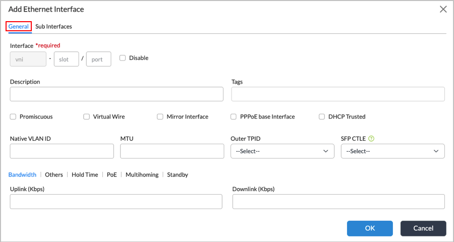
Field Description Interface (Required) Enter the port and slot numbers for the VNI interface. Disable Click to not activate the interface after you configure it. Description Enter a text description for the interface. It can be a text string up to 255 characters. Tags Enter text strings that describe the Ethernet interface. A tag is an alphanumeric text descriptor with no spaces or special characters. You can specify multiple tags added for the same object. The tags are used for searching the objects. Promiscuous Click to have the interface accept all data packet sent towards it. Virtual Wire Click if the interface is part of a virtual wire. When you select this option, you cannot configure any other parameters on the popup window. Mirror Interface Click to create a copy of the interface. PPPoE-Based Interface Click to have the interface act as a Point-to-Point Protocol over Ethernet (PPPoE) interface. In a PPPoE session, the device encapsulates each Point-to-Point Protocol (PPP) frame in an Ethernet frame and transports the frames over an Ethernet loop. DHCP Trusted Click to configure the interface as a DHCP trusted interface. A DHCP trusted interface accepts DHCP response and acknowledgement (ACK) packets from the DHCP server. Native VLAN ID Enter the native VLAN ID for the Ethernet interface. MTU Enter the maximum transmission unit size, in bytes, of the largest protocol data unit that the port can receive or transmit.
Range: 72 through 9000 bytesOuter TPID Select the outer tag protocol identifier (TPID), which is a 16-bit field that identifies the frame as an IEEE 802.1Q-tagged frame:
- 0x8100
- 0x88a8—Select if you are configuring Q-in-Q for routed interfaces (dual VLAN).
SFP CTLE (For Release 22.1.4 and later.) Select the CTLE (continuous time linear equalizer) value for the small form-factor pluggable (SFP) interface. This setting determines the level of analog equalization that the SFP module receiver applies to compensate for signal degradation over high-speed copper or fiber links.
Available values are 0 through 10, and Disable. Values from 0 to 10 represent increasing levels of equalization strength; the higher the value, the more equalization the receiver applies to correct signal degradation caused by the transmission medium.
Bandwidth (Tab) Specify the bandwidth available on a link to upload and download data. This information is used in computing adaptive traffic shaping. - Uplink
Enter the bandwidth available on the link for uploading data, in kilobits per second (Kbps).
Range: 1 through 10000000 Kbps
Default: None
- Downlink
Enter the bandwidth available on the link for downloading data, in kilobits per second (Kbps).
Range: 1 through 10000000 Kbps
Default: None
Others (Tab)
For bare-metal devices only.

- Link Speed
Select the speed of the link:
- Auto Speed (Default)
- 10-Mbps Interface
- 100-Mbps Interface
- 1-Gbps Interface
- Link Mode
Select the mode to use on the link:
- Auto Duplex (Default)
- Half-Duplex Interface
- Full-Duplex Interface
Hold Time (Tab) (Group of Fields) 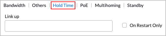
- Link Up
Enter the link up hold time, in milliseconds. When you configure a link up hold time, when the interface state goes from Down to Up, the hold time is triggered. The VOS device holds the link state as down for the configured interval, and any interface state transitions that occur during this time are ignored. When the hold time expires, if the interface state is Up, the VOS device advertises the interface as being active.
Range: 0 through 4294967295 milliseconds
Default: None
- On Restart Only
Enable Link Up only when the system restarts. Power over Ethernet (PoE) (Tab)
(For Releases 21.2.1 and later.) Configure PoE parameters on PoE interfaces for CSG appliances. When configuring PoE, you can enable the PoE interface for the port to provide power to a connected device. When a new device connects on a higher-priority port, a lower-priority port if powered off automatically if the overall power budget of the NIC is exceeded.

- Power Mode
Select Enabled or Disabled. Multihoming (Tab) (Group of Fields)
(For Releases 21.2.1 and later.) Configure the EVPN multihoming mode.

- Active Mode
Select the active mode:
- All Active
- Single Active
- ESI
Enter a hexadecimal number for the Ethernet Segment Indicator (ESI). Standby (Group of Fields) - Activate on Monitor (Group of Fields)
Select to activate standby mode based on a monitor.
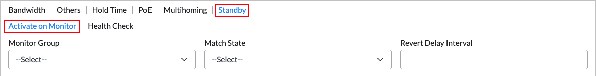
- Monitor Group
Select the name of monitor group. - Match State
Select the match state of the monitor group to match:
- Down
- Up
- Revert Delay Interval
Enter the revert interval delay, in seconds.
Range: 1 through 360 seconds
Default: None
- Health Check (Group of Fields)
Select to perform a periodic health check on the subinterface.

- Track Monitor
Select the monitor to use use for tracking.
- Interval
Enter how long to wait before performing a health check on the subinterface.
Range: 1 through 720 hours
Default: None
- Wait Interval
Enter how long to wait for the monitor to evaluate the health of the subinterface.
Range: 1 through 59 minutes
Default: None
- Select the Subinterfaces tab. In the Subinterfaces screen, select the Subinterfaces button (if it is not already selected).

- Click the Add icon to add a subinterface. You can configure up to 4095 subinterfaces on an interface. In the Add Subinterface screen, click the General subtab and enter information for the following fields.
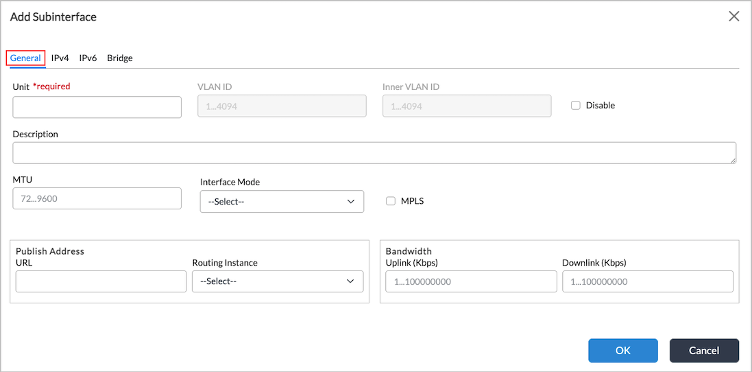
Field Description Unit (Required) Enter a unit number for the subinterface. VLAN ID Enter the virtual LAN ID for the subinterface.
Range: 0 through 4094
Inner VLAN ID Enter the inner VLAN ID for the subinterface. Disable Click to not activate the subinterface after you configure it. Description Enter a text description for the subinterface. It can be a text string up to 255 characters. MTU Enter the size, in bytes, of the largest protocol data unit that the subinterface can receive or transmit.
Range: 72 through 9600 bytes
Interface Mode Select the interface mode:
- Normal
- NSH Reflect
- Redundancy
MPLS Select to enable MPLS on the subinterface. Publish Address (Group of Fields) - URL
Enter the URL to access. - Routing Instance
Select the routing instance for the subinterface to use to access the URL. Bandwidth (Group of Fields) - Uplink
Enter the bandwidth available on the subinterface for uploading data, in kilobits per second (Kbps). If you configure SD-WAN traffic steering, this value is used by the selection connection method that selects how to forward a traffic flow when multiple available WAN paths have the highest priority. For more information, see Configure SD-WAN Traffic Steering. Note that this value does not affect the CoS (QoS) configuration on the interface.
Range: 1 through 10000000 Kbps
Default: None
- Downlink
Enter the bandwidth available on the subinterface for downloading data, in kilobits per second (Kbps). If you configure SD-WAN traffic steering, this value is used by the selection connection method that selects how to forward a traffic flow when multiple available WAN paths have the highest priority. For more information, see Configure SD-WAN Traffic Steering. Note that this value does not affect the CoS (QoS) configuration on the interface.
Range: 1 through 10000000 Kbps
Default: None
- Select the IPv4 tab, then enter information for the following fields.

Field Description Enable IPv4 Click the  slider bar to enable IPv4. By default, IPv4 is disabled.
Static Address Click to configure a static IPv4 address on the subinterface. Click the Add icon, then enter an IPv4 address and subnet mask. If you select Static Address, you cannot select DHCPv4.DHCPv4 (Group of Fields) Click to configure a DHCPv4 address on the subinterface. - Route Preference
Enter a value for the route preference.
Range: 1 through 255
Default: None
- Vendor Class Identifier
(For Releases 21.2.1 and later.) Enter the vendor class identifier. - Disable Broadcast Flag
Click to disable broadcast on the subinterface's network. - Reachability Monitor (Group of Fields)
- Interval
Enter the time interval after which ICMP reports error messages. - Threshold
Enter the maximum number of ICMP error messages to report. - Enable ICMP
Click to enable ICMP on the subinterface. - Lease Time (Group of Fields)
The amount of time that the DHCPv4 address is valid. - Days
Enter the number of days for the lease time. - Hours
Enter the number of hours.
Range: 0 through 23
Default: None
- Minutes
Enter the number of minutes.
Range: 0 through 59
Default: None
FQDN Enter the fully qualified domain name for the DHCPv4 subinterface. Directed Broadcast
Click to enable directed broadcast, which sends broadcast packets targeted at hosts in a specified subnet. ICMP Reply (For Releases 23.1.2 and later.) By default, VOS devices reply to ICMP requests. If you uncheck this checkbox, the VOS devices will not reply to ICMP requests. SLA Endpoint
Click to make the subinterface an SLA endpoint. When enabled, the subinterface will be used as source address (by appliance on which it is enabled) and destination address (by other SD-WAN appliances) for sending IP-SLA probes for Data-Driven SLA Monitoring. Static ARP (Tab)
Select to configure a static ARP mapping. - Subnet Address/Mask (Required)
Select the static address and mask. - Host IP Address (Required)
Enter the IP address of the host. - MAC Address (Required)
Enter the MAC address of the host. VRRP tab To configure VRRP, see Step 9. Standby (Tab)
- Activate on Monitor (Tab)
Select the Activate on Monitor tab, and enter information for the following fields.
- Monitor Group—Select a monitor group.
- Match State—Select a match state:
- Down
- Up
- Revert Delay Interval—Enter the revert interval delay value, in seconds.
Range: 1 through 360 seconds
Default: 10 seconds
- Health Check (Tab)
(For Releases 21.2.1 and later.) Perform a periodic health check on an interface. Enter information for the following fields.
- Track Monitor—Select a monitor to track.
- Interval— How long to wait before performing a health check on an interface.
Range: 1 through 720 hours
Default: 10 hours
- Wait Interval—How long to wait for the monitor to evaluate the health of an interface.
Range: 1 through 59 minutesDefault: 10 minutes
Proxy ARP (Tab)
(For Releases 21.2.1 and later.) Configure proxy ARP.
To use proxy ARP, you configure a set of IPv4 subnet prefixes or prefix ranges to which proxy ARP on the VOS device responds if no ARP entry for an IP address is available. Using a proxy ARP allows a VOS device to respond to ARP requests for IP addresses configured in NAT pools that are both within and outside of the interface’s subnet. Proxy ARP provides local responses, allowing a VOS device to reduce the amount of broadcast traffic over Layer 2 networks (such as EVPN) across SD-WAN and VXLAN.
The MAC address used in response to proxy ARP requests is the port’s physical MAC address, which is the MAC address used in reponse to the interface IP address.
When the VOS device installs proxy ARP addresses and responds to proxy ARP requests, the VOS device considers the interface’s VRRP state. If the VRRP interface state is not active, the VOS device does not respond to an ARP request for these IP addresses, and the control plane removes the entries provisioned in the data path. This behavior is similar to how devices configured with VRRP respond to the VRRP virtual IP address.
When you enable proxy ARP, the existing static ARP configuration in the IPv4 address hierarchy remains unchanged.
Note that the IP address range or subnet that you configure for proxy ARP does not need to be within the interface’s subnet. You must ensure that the requestor or the peer is in same subnet as the interface IP address.
- Proxy ARP Addresses
Click the
Add icon, and enter the proxy ARP addresses. You can add multiple proxy ARP addresses.
- Proxy ARP Address Ranges
Enter the following information:

- Range Name (Required)—Enter a name for the address range.
- IP High (Required)—Enter the highest IP address in the address range.
- IP Low (Required)—Enter the lowest IP address in the address range.
- Click the
 Add icon to add the address range.
- Select the IPv6 tab in the Add Subinterface screen, and enter information for the following fields.

Field Description Enable IPv6 Click the slider bar to enable IPv6. By default, IPv6 is disabled.Static Address
Click to use a static IPv6 address for the subinterface. IPv6 Address/Mask
Click the Add icon, and enter the IPv6 address and prefix length of the static address.Delegated Prefix Pool
Enter the name and IPv6 address of a delegated prefix pool, and then click the Add icon to add the prefix pool.DHCPv6 (Group of Fields)
Click to use DHCP to assign an IPv6 address for the subinterface. - Client IA Type
Select the client identity-association (IA) type, which is a collection of addresses assigned to a client:
- EUI-64 (Extended Unique Identifier)—Allows a host to assign itself a unique 64-bit IPv6 interface identifier
- IA-NA (non-temporary addresses)
- IA-NONE
- IA-PD (prefix delegation)
- Delegated Prefix Pool
For client IA type IA-PD, enter the IP address of the delegated prefix pool. Neighbor Discovery (Group of Fields) - Cache Lifetime (secs)
Enter how long cache entries are retained in the neighbor discovery cache, in seconds.
Range: 0 through 65535 seconds
Default: 30
- Retransmit Interval (secs)
Enter the time interval between retransmissions of neighbor discovery messages, in seconds.
Range: 0 through 65535 seconds
Default: 1
- Route Preference
Enter the route preference value. A lower value gives higher precedence to the route.
Range: 1 through 255
Default: 2
IPv6 Interface Mode
Select the IPv6 interface mode:
- Host—This is the default. Use to configure stateful DHCPv6.
- Router—Select to configure stateless automatic address configuration (SLAAC). You must also configure a router advertisement that corresponds to the IPv6 address and prefix length. For more information, see Configure Virtual Routers.
FQDN
Enter the fully qualified domain name for the IPv6 subinterface. Interface Identifier Enter a valid IPv6 address as the interface identifier. SLA Endpoint Click to make the subinterface is an SLA endpoint. When enabled, the subinterface will be used as source address (by appliance on which it is enabled) and destination address (by other SD-WAN appliances) for sending IP-SLA probes for Data-Driven SLA Monitoring. ICMP Reply (For Releases 23.1.2 and later.) By default, VOS devices reply to ICMP requests. If you uncheck this checkbox, the VOS devices will not reply to ICMP requests. VRRP (Tab)
To configure VRRP, see Step 10. Proxy NDP (Tab)

(For Releases 21.2.1 and later.) Configure proxy Neighbor Discovery Protocol (NDP).To use proxy NDP, you configure a set of IPv6 subnet prefixes or prefix ranges to which proxy NDP on the VOS device responds if no NDP entry for an IP address is available. Proxy NDP allows a VOS device to respond to NDP requests for IP addresses configured in NAT pools that are both within and outside of the interface’s subnet. Proxy NDP provides local responses, allowing a VOS device to reduce the amount of broadcast traffic over Layer 2 networks (such as EVPN) across SD-WAN and VXLAN.
IPv6 NAT supports proxy NDP for Network Prefix Translation version 6 (NPTv6).
Click the
Add icon to configure IPv6 addresses and prefix lengths for proxy NDP. The IP address range or subnet that you configure for proxy NDP does not need to be within the interface’s subnet. You must ensure that the requestor or the peer is in same subnet as the interface IP address. - Select the Bridge tab, and enter information for the following fields.

Field Description Enable Bridge Click the slider bar to enable Bridge. By default, Bridge is disabled.Interface Mode
Select the interface mode:
- Access
- Trunk
dot1x
(For Releases 21.2.1 and later.) Click to enable 801.1X on the subinterface. VLAN ID
For the Access interface mode, enter the VLAN ID for the subinterface.
Range: 1 through 4094
Note: If you selected the dot1x checkbox above or the Trunk interface mode, the VLAN ID field is grayed out.
VLAN ID List
For the Trunk interface mode, enter the VLAN ID list for the subinterface.
Range: 1 through 4094
- Select the IPv4 > VRRP tab or the IPv6 > VRRP tab to configure active and standby VRRP devices for high availability (HA). With HA, the standby device takes over if the active one is down, thus helping to ensure an uninterrupted traffic flow.
- Click the Add icon to configure a VRRP group. The Add Subinterface Add VRRP Group screen displays.

- In the General tab, enter information for the following fields.
Field Description Group ID (Required) Enter an identifier for the VRRP group.
Range: 1 through 255
Default: None
Address (Required) Enter the IP address of the interface on which to configure the VRRP group. Priority Enter the priority to assign to the interface. The interface with the higher or highest priority becomes the VRRP active router.
The priority value that you configure can be reduced by various objects that VRRP tracks, such as interfaces, routes, monitor objects, and HA state. When choosing a priority value, make sure that you account for a worst-case scenario so that the priority never goes below 0. For example, consider a VRRP group configured on interface vni-0/0.0 with priority of 200 and that is tracking interface vni-0/1.0, which has a priority cost of 20. Here, the vni-0/1.0 interface is the tracking object. If the vni-0/1.0 interface goes down, its priority cost is subtracted from the configured priority of 200, and so the current (dynamic) priority becomes (200 – 20), or 180.
Range: 1 through 255
Default: 100Peer Address Enter the address of the peer interface. Inherit Configuration (Group of Fields) Click to have VRRP inherit the properties of another interface. If you select this option, the following items are grayed out: Track tab, Preempt Mode field, Advertisements Threshold field, Warmup Interval field, and Fast Interface field.
- Interface Name
Select the name of the interface whose configuration properties are to be inherited. - VRRP Group ID
Enter the VRRP group ID of the interface whose configuration properties are to be inherited. Preempt Mode Select how the VRRP active router is elected from among the routers in the VRRP group:
- No Preempt—When a VRRP active router goes down and a backup router takes over as the active router, the previous active router remains a backup router when it comes back up even though it has a higher priority than the router that has taken over as the active router.
- Preempt—When a VRRP active router goes down and a backup router takes over as the active router, the previous active router takes over again as the active router as soon as it comes back up, because it has a higher priority than the backup router. This is the default mode.
Default: Preempt
Advertisements Threshold Enter the number of VRRP advertisements that the backup router can miss before declaring the active router to be down.
Range: 1 through 15
Default: None
Warmup Interval Enter how long the interface waits, in seconds, before determining which VRRP router is the active router and which is the backup.
Range: 1 through 3600 seconds
Virtual Address (Required) Click the Add icon, then enter the virtual IP address or addresses to include in the VRRP group.HA Standby Priority Cost Enter the value to subtract from the priority when the interchassis HA state of the VOS device changes from active to standby.
Range: 1 through 254
Default: 100
For more information, see Considerations for Configuring Interchassis HA and VRRP.
Accept Data Click to have the interface accept data that it receives. Otherwise, the data is routed to another interface. - Select the Track tab to configure tracking for the VRRP group. Enter information for the following fields.

Field Description Priority Hold Time Enter the virtual router priority hold time, in seconds.
Range: 0 through 3600 seconds
Default: None
Interface (Tab) - Name (Required)
Select the primary interface on the active router in the VRRP group. - Priority Cost
Enter the cost for the interface. The router with the highest priority in the VRRP group is or becomes the active router.
Range: 1 through 254
Default: 100
- Add icon
Click to add the interface. Routes (Tab) 
- Prefix (Required)
Enter the route prefix. - Routing Instance (Required)
Select the routing instance. - Priority Cost (Required)
Enter the cost for the interface. The router with the highest priority in the VRRP group is or becomes the active router.
Range: 1 through 254
Default: 100
- Add icon
Click to add the route. Monitors (Tab) 
- Name (Required)
Select the primary interface on the active router in the VRRP group. - Priority Cost
Enter the cost for the interface. The router with the highest priority in the VRRP group is or becomes the active router.
Range: 1 through 254
Default: 100
- Add icon
Click to add the monitor.
- Click the
- Click OK.
Configure Aggregate Ethernet Interfaces on a WAN Interface
You can configure an aggregate Ethernet interface, which is a logical interface comprised of two or more Ethernet interfaces, on a WAN interface. It is the parent interface and has vni (Ethernet) interfaces as its children. Aggregate interface names start with ae. An aggregated Ethernet interface can increase overall throughput, and it provides redundancy in case one of the links fails.
To configure an aggregated Ethernet interface on a WAN interface, first you configure the individual interfaces that are the members of the aggregation, and then you configure the aggregated Ethernet interface itself. For the member interfaces, you must configure Layer 2 interfaces. You must also configure integrated routing and bridging (IRB) on a WAN interface.
Configure the Individual Interfaces
You configure the individual interfaces that are the members of the aggregated Ethernet interface in an SD-WAN device template. You configure the following types of interfaces:
- Layer 2 interfaces—Interfaces that you want to aggregate as Layer 2 interfaces. You must configure at least two device ports as Layer 2 interfaces so that the aggregated Ethernet interface has at least two members.
- IRB interface—Associates a Layer 3 interface with the Layer 2 interfaces in so that packets can be routed between the Layer 2 LAN network and the Layer 3 WAN network.
Before you begin, you must already have a created have a post-staging template. For more information, see Create and Manage Staging and Post-Staging Templates.
Start the Interface Configuration Wizard
To configure the individual interfaces for the aggregated Ethernet interface, first navigate to the interface configuration wizard:
- In Director view, select the Workflows tab in the top menu bar.
- Select Templates > Templates in the horizontal menu bar.
- Select an organization in the Organization field.
- Select the SD-WAN tab. The screen displays the templates that are already configured.

- Select a template to edit. The interface configuration wizard displays, with Step 1, Basic highlighted be default.

Configure Layer 2 Interfaces
Configure one or more Layer 2 interfaces:
- In the configuration wizard, click Next or Step 2, Interfaces. The Step 2, Configure Interfaces screen displays a graphic showing the ports on the device.

- To configure a Layer 2 interface, click the port number, and then select Layer 2 in the popup window.

- The Device Port Configuration screen displays with the selected port in green. Enter information for the following fields.

Field Description VLANs Enter the VLAN ID to associate with the Layer 2 interface. Use the same VLAN ID for all the Layer 2 interfaces that are members of the aggregated Ethernet interface.
Mode Select Access as the traffic mode.
- Click Add.
- Repeat Steps 2 through 4 for each additional Layer 2 interface that you want to be a member of an aggregated Ethernet interface.
- Click Done. The screen shows the configured interfaces on the Layer 2 Interfaces tab, here, vni-0/4 and vni-0/5.

Configure an IRB Interface
To configure an IRB interface:
- In the Device Port Configuration window, click Configure in the Virtual Ports field. The Virtual Port Configuration screen displays.
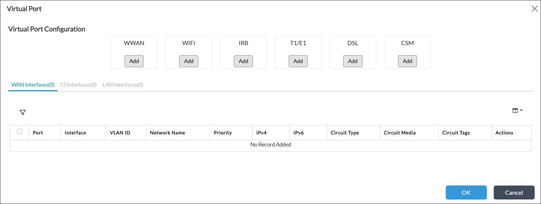
- In the IRB field, click Add, and then select WAN in the popup field.

- In the Virtual Port Configuration window, enter information for the following fields.
Field Description VLAN ID Enter the VLAN ID for the interface. Use the same VLAN ID that you configured for the Layer 2 interfaces.
Network Select the network to which the interface connects.
- Click Add.
- Click OK. The WAN Interfaces tab shows the IRB interface, here, irb1.

Deploy the Template
- In the configuration wizard, click Step 8, Review.

- Click Deploy to deploy the template.
Configure the Aggregated Ethernet Interface
- In Director view:
- Select the Administration tab in the top menu bar.
- Select Appliances in the left menu bar.
- Select a device name in the main panel. The view changes to Appliance view.
- Select the Configuration tab in the top menu bar.
- Select Networking > Interfaces in the left menu bar.
- Select the AE tab, then click the Add icon to configure a new AE interface. The Add Ethernet Interface screen displays with the General tab selected by default.

Field Description Interface (Required) Enter a number for the aggregated Ethernet interface. Aggregated Ethernet interface names start with ae.
Promiscuous Click to enable promiscuous mode for the aggregated Ethernet interface. Note that you must enable promiscuous mode for Layer 2 interfaces.
- Select the Subinterfaces tab, and then click the Add icon. The Add Subinterface popup window displays with the General tab selected by default.
- Enter a number in the Unit field.
- Select the IPv4 tab. See Step 7 above for information about configuring the IPv4 tab.
- Select the IPv6 tab. See Step 8 above for information about configuring the IPv6 tab.
- Select the Bridge tab, and then click the slider bar to enable the Bridge option.
- Enter information for the following fields.
Field Description Interface mode Select Access.
Note: If you select an interface mode, the IPv4 and IPv6 tabs are disabled. Deselect Interface Mode to enable IPv4 IPv6 configuration.
VLAN ID Enter the VLAN ID to associate with the interface. Use the same VLAN ID that you configured for the Layer 2 interfaces to join as members of the aggregated Ethernet interface.

- Click OK to add the subinterface.
- Click OK to add the aggregated Ethernet interface.
- Select the VNI Interfaces tab, and then select one of the Layer 2 interfaces that you created to add to the aggregated Ethernet interface.
- In the Edit Ethernet Interface popup window, select the Subinterfaces tab.
- Click Aggregate Member, and in the Interface field, select the aggregated Ethernet interface, here, ae0.
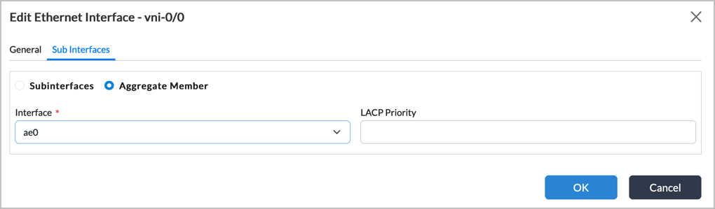
- Click OK.
- Repeat Steps 10 through 16 for each interface that you want to add to the aggregated Ethernet interface.
- Select Others > Organization > Limits in the left menu bar.
- Select the organization. The Edit Organization Limit window displays.
- Select the Traffic Identification tab. In the Interfaces table, select the VNI interfaces that you added as members of the aggregated Ethernet interface.

- Click the
 Trash icon to remove the interfaces from the list.
 - In the Interfaces table, click the
 Add icon, and then select the aggregated Ethernet interface, here, ae0.1.
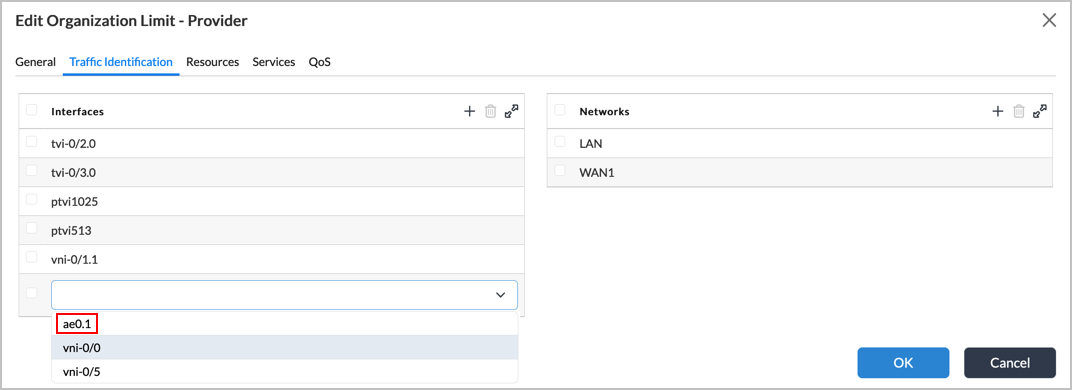
- Click OK.
- Select Networking > Virtual Switches in the left menu bar.
- Select the virtual switch. The Edit Virtual Switch popup window displays.
- In the Interfaces table, select the vni interfaces that you added as members of the aggregated Ethernet interface.

- Click the Trash icon to remove the interfaces from the list.
- In the Interfaces table, click the Add icon and select the aggregated Ethernet interface, here, ae0.1.

- If the Spanning-Tree Protocol in enabled, select the Spanning-Tree Protocol tab.
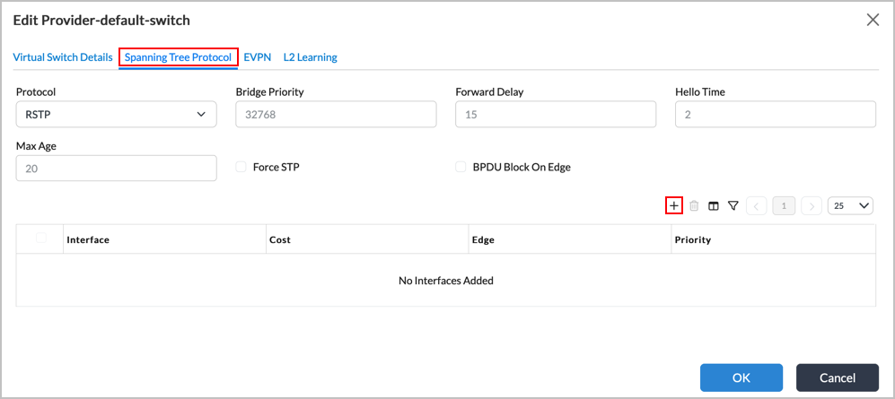
- In the Interface table, click the Add icon. The Add Interfaces popup window displays.
- In the Interface field, select the aggregated Ethernet interface, and then click OK.
- Click OK.
Configure LAN Ethernet Interfaces
For Releases 22.1.1 and later.
You can configure the following types of Ethernet interfaces for LAN networks on VOS Layer 2 switches:
- Ethernet
- Aggregated Ethernet, which is a logical linkage of Ethernet connections
LAN Ethernet interfaces are named with the prefix enet, for example, enet0/5.
To configure a LAN Ethernet interface:
- Select Director View in the top menu bar.
- Select Configuration > Devices > Devices in the horizontal menu bar.
- Click the name of an appliance. The view changes to Appliance view, with the Configuration tab selected in the horizontal menu bar.
- Select Networking > Interfaces in the left menu bar.
- Select the ENet tab in the horizontal menu bar. The following screen displays.

- Click Add to add a LAN Ethernet interface. The Add Enet Interface window displays.
- Select the General tab, and then enter information for the following fields.

Field Description Interface (Required) Enter the port and slot numbers for the enet interface. Disable Click if you do not want to activate the interface after you configure it. Description Enter a text description for the interface. It can be a text string up to 255 characters. Tags Enter one or more text strings that describe the Ethernet interface. A tag is an alphanumeric text descriptor with no white spaces or special characters that you can use to search interface names. You can specify multiple tags. Promiscuous Click to have the interface accept all data packets sent towards it. Virtual Wire Click if the interface is part of a virtual wire. When you select this option, you cannot configure any other parameters on the popup window. Mirror Interface Click to create a copy of the interface. PPPoE-Based Interface Click to have the interface act as a Point-to-Point Protocol over Ethernet (PPPoE) interface. In a PPPoE session, the device encapsulates each Point-to-Point Protocol (PPP) frame in an Ethernet frame and transports the frames over an Ethernet loop. DHCP Trusted (For Releases 22.1.3 and later.) Click to enable the ports to be DHCP trusted ports. You can designate a port as trusted for DHCP if it connects to a legitimate DHCP server. This allows the port to send DHCP requests and acknowledgements. Dynamic Interface Click the checkbox to make the interface a dynamic smart port. For more information, see Configure Dynamic Smart Ports. Native VLAN ID Enter the native VLAN ID for the Ethernet interface. MTU Enter the maximum transmission unit (MTU) size, in bytes, of the largest PDU that the port can receive or transmit.
Range: 72 through 9000 bytesOuter TPID Select the outer tag protocol identifier (TPID), which is a 16-bit field that identifies the frame as an IEEE 802.1Q-tagged frame:
- 0x8100
- 0x88a8—Select if you are configuring Q-in-Q for routed interfaces (dual VLAN).
Role (For Releases 22.1.3 and later.) Select the user's role:
- Client Port
- Uplink Port
SFP CTLE (For Release 22.1.4 and later.) Select the CTLE (continuous time linear equalizer) value for the small form-factor pluggable (SFP) interface. This setting determines the level of analog equalization that the SFP module receiver applies to compensate for signal degradation over high-speed copper or fiber links.
Available values are 0 through 10, and Disable. Values from 0 to 10 represent increasing levels of equalization strength; the higher the value, the more equalization the receiver applies to correct signal degradation caused by the transmission medium.
Breakout Mode (For Releases 22.1.4 and later.) For CSG3000 series devices, CSX4000 switches, and CSX8000 switches, select the Ethernet port breakout mode. You can use port breakout to channelize a high-bandwidth port into multiple independent lower-speed ports. You can use port breakout on ports that are 100-Gigabit Ethernet or faster. For example, you can break out a 100-Gigabit Ethernet port into the following speed ports:
- One 40-GB port
- Two 50-GB ports
- Four 10-GB ports
- Four 25-GB ports
Bandwidth (Tab) Specify the bandwidth available on a link to upload and download data. This information is used in computing adaptive traffic shaping.

- Uplink
Enter the bandwidth available on the link for uploading data, in kilobits per second (Kbps).
Range: 1 through 10000000 Kbps
Default: None
- Downlink
Enter the bandwidth available on the link for downloading data, in Kbps.
Range: 1 through 10000000 Kbps
Default: None
Others (Tab) Configure link-related parameters.
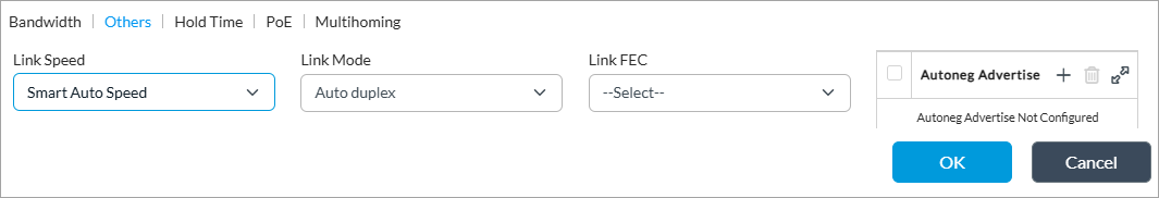
- Link Speed
Select the speed of the link:
- Auto Speed—Automatically determine the speed of the link.
- Smart Auto Speed—(For Releases 22.1.4 and later.) For Ethernet ports, the system automatically reverts to the fixed link speed if auto speed negotiation fails. For SFP ports, the system automatically detects the inserted SFP module and applies default configuration settings.
- 10-Mbps Interface
- 100-Mbps Interface
- 1-Gbps Interface
- 2.5-Gbps Interface
- 10-Gbps Interface
- 20-Gbps Interface
- 25-Gbps Interface
- 40-Gbps Interface
- 50-Gbps Interface
- 100-Gbps Interface
- Link Mode
Select the mode to use on the link:
- Auto Duplex—Automatically determine the mode of the link.
- Half-Duplex Interface
- Full-Duplex Interface
- Link FEC
Select the type of forward error correction (FEC) to use, if any:
- None
- Auto
- fec74
- fec91
- fec108
Hold Time (Tab) 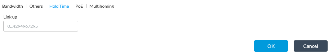
- Link Up
Enter the link up hold time, in milliseconds. When you configure a link up hold time, when the interface state goes from Down to Up, the hold time is triggered. The VOS device holds the link state as down for the configured interval, and any interface state transitions that occur during this time are ignored. When the hold time expires, if the interface state is Up, the VOS device advertises the interface as being active.
Range: 0 through 4294967295 milliseconds
Default: None
PoE (Tab) Configure PoE parameters on PoE interfaces. When configuring PoE, you can enable the PoE interface for the port to provide power to a connected device. When a new device connects on a higher-priority port, a lower-priority port is powered off automatically if the overall power budget of the NIC is exceeded.

- Power Mode
Select the power mode:
- Disabled
- Enabled
- Priority
(For Releases 22.1.4 and later.) For CSG3000 series devices and CSX4000 switches, select the PoE port priority to determine which ports to power off in case of insufficient power. When two ports have the same priority value, the higher port number is powered off before the lower port number.
- Low
- Medium
- High
- Critical
Default: Low
Multihoming (Tab) Configure EVPN multihoming mode.

- Active Mode
Select the active mode:
- All Active
- Single Active
- ESI (Required)
Enter a hexadecimal list for the Ethernet Segment Indicator (ESI). - Select the Subinterfaces tab. The window displays the subinterfaces that are already configured.
.png?revision=1)
- Click the Add icon to configure a new subinterface. The Add Subinterface window displays. You can configure up to 4095 subinterfaces on an interface.
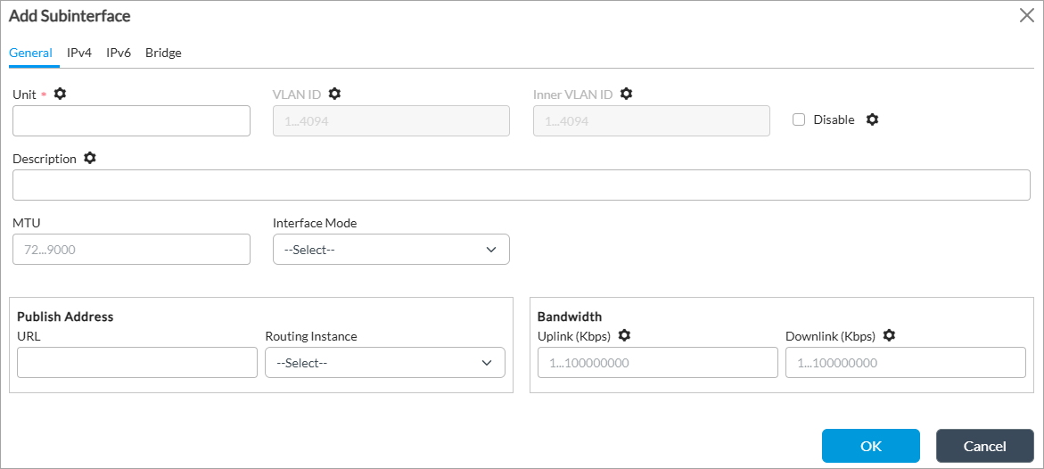
- Select the General tab on the Add Subinterface window, and then enter information for the following fields.
Field Description Unit (Required) Enter a unit number for the subinterface. VLAN ID Enter the virtual LAN ID for the subinterface.
Range: 0 through 4094
Inner VLAN ID Enter the inner VLAN ID for the subinterface. Disable Click if you do not want to activate the subinterface after you commit the configuration. Description Enter a text description for the interface. It can be a text string up to 255 characters. MTU Enter the size, in bytes, of the largest PDU that the subinterface can receive or transmit.
Range: 72 through 9000 bytes
Interface Mode Select the interface mode:
- Normal
- NSH Reflect
- Redundancy
Publish Address (Group of Fields) - URL
Enter the URL to access. - Routing Instance
Select the routing instance for the subinterface to use to access the URL. Bandwidth (Group of Fields) - Uplink
Enter the bandwidth available on the subinterface for uploading data, in Kbps.
Range: 1 through 10000000 Kbps
Default: None
- Downlink
Enter the bandwidth available on the subinterface for downloading data, in Kbps.
Range: 1 through 10000000 Kbps
Default: None
- Select the IPv4 tab on the Add Subinterface window, and then enter information for the following fields.

Field Description Static Address Click to use a static IPv4 address for the subinterface. You can configure either a static IPv4 address or use DHCP on the subinterface, but not both. Static Address Click the Add icon and enter the IPv4 address to use for the subinterface.DHCPv4 (Group of Fields) Click to use DHCP to dynamically assign an IPv4 address to the subinterface. You can configure either a static IPv4 address or use DHCP on the subinterface, but not both. - Route Preference
Enter the preference for the traffic route. A lower preference value indicates a higher preference for using the route.
Range: 1 through 255
Default: None
- Vendor Class Identifier
Enter the vendor class identifier. - Disable Broadcast Flag
Click to disable broadcasting on the subinterface's network. - Reachability Monitor (Group of Fields)
Configure a reachability monitor.
- Interval
Enter the time interval after which ICMP reports error messages. - Threshold
Enter the maximum number of ICMP error messages to report. - Enable ICMP
Click to enable ICMP on the subinterface. FQDN Enter the fully qualified domain name for the IPv4 subinterface. Directed Broadcast Click to enable directed broadcast, which sends broadcast packets targeted at hosts in a specified subnet. SLA Endpoint Click to make the subinterface is an SLA endpoint. When enabled, the subinterface will be used as source address (by appliance on which it is enabled) and destination address (by other SD-WAN appliances) for sending IP-SLA probes for Data-Driven SLA Monitoring. - On the IPv4 tab on the Add Subinterface window, select the Static ARP tab in the horizontal menu bar to configure a static ARP mapping, and then enter information for the following fields.
Field Description Subnet Address/Mask (Required) Select the static address and mask. Host IP Address (Required) Enter the IP address of the host. MAC Address (Required) Enter the MAC address of the host. Add iconClick to add the static ARP entry. - On the IPv4 tab on the Add Subinterface window, select the VRRP tab in the horizontal menu bar to configure active and standby VRRP devices for high availability (HA) on the subinterface.

- Click the Add icon. In the Add Subinterface Add VRRP Group window, and then enter information for the following fields.

Field Description Group ID (Required) Enter an identifier for the VRRP group.
Range: 1 through 255
Default: None
Address (Required) Enter the IPv4 address of the subinterface on which to configure the VRRP group. Priority Enter the priority to assign to the interface. The interface with the higher or highest priority becomes the VRRP active router.
The priority value that you configure can be reduced by various objects that VRRP tracks, such as interfaces, routes, monitor objects, and HA state. When choosing a priority value, make sure that you account for a worst-case scenario so that the priority never goes below 0. For example, consider a VRRP group configured on interface enet-0/0.0 with priority of 200 and that is tracking interface enet-0/1.0, which has a priority cost of 20. Here, the vni-0/1.0 interface is the tracking object. If the enet-0/1.0 interface goes down, its priority cost is subtracted from the configured priority of 200, and so the current (dynamic) priority becomes (200 – 20), or 180.
Range: 1 through 255
Default: 100Peer Address Enter the address of the peer subinterface. Inherit Configuration (Gropup of Fields) Click to have VRRP inherit the properties of another interface.
- Interface Name
Select the name of the subinterface whose configuration properties are to be inherited. - VRRP Group ID
Enter the VRRP group ID of the subinterface whose configuration properties are to be inherited. Preempt Mode Select how the VRRP active router is elected from among the routers in the VRRP group:
- Preempt—When a VRRP active router goes down and a backup router takes over as the active router, the previous active router takes over again as the active router as soon as it comes back up, because it has a higher priority than the backup router. This is the default mode.
- No Preempt—When a VRRP active router goes down and a backup router takes over as the active router, the previous active router remains a backup router when it comes back up even though it has a higher priority than the router that has taken over as the active router.
Default: Preempt
Advertisements Threshold Enter the number of VRRP advertisements that the backup router can miss before declaring the active router to be down.
Range: 1 through 15
Default: None
Warmup Interval Enter how long the interface waits, in seconds, before determining which VRRP router is the active router and which is the backup.
Range: 1 through 3600 seconds
Virtual Address (Required) Configure a virtual address for the subinterface. - IP Address (Required)
Enter the virtual IP address or addresses to include in the VRRP group, and then click the Add icon.HA Standby Priority Cost Enter the value to subtract from the priority when the interchassis HA state of the VOS device changes from active to standby.
Range: 1 through 254
Default: 100Fast Interval (msec) For VRRP Version 3 only, enter how often the active and backup routers exchange VRRP advertisement messages, in milliseconds.
Range: 10 through 50000 milliseconds
Accept Data Click to have the interface accept data that it receives. Otherwise, the data is routed to another interface. - Click OK to add the VRRP group to the subinterface.
- On the IPv4 tab on the Add Subinterface window, select the Standby tab in the horizontal menu bar to activate standby mode based on a monitor, and then enter information for the following fields.

Field Description Activate on Monitor (Tab) Select to activate standby mode based on a monitor. - Monitor Group
Select the name of monitor group. - Match State
Select the match state of the monitor group to match:
- Down
- Up
- Revert Delay Interval
Enter the revert interval delay, in seconds. Range: 1 through 360 seconds
Default: 10 seconds
Health Check (Tab) Select to perform a periodic health check on the subinterface. - Track Monitor
Select the monitor to use use for tracking. - Interval
Enter how long to wait before performing a health check on the subinterface. Range: 1 through 720 hours
Default: 10 hours
- Wait Interval
Enter how long to wait for the monitor to evaluate the health of the subinterface.
Range: 1 through 59 minutesDefault: 10 minutes
- On the IPv4 tab on the Add Subinterface window, select the Proxy ARP tab in the horizontal menu bar to configure proxy ARP, and then enter information for the following fields.
To use proxy ARP, you configure a set of IPv4 subnet prefixes or prefix ranges to which proxy ARP on the VOS device responds if no ARP entry for an IP address is available. Using proxy ARP allows a VOS device to respond to ARP requests for IP addresses configured in NAT pools that are both within and outside of the interface’s subnet. Proxy ARP provides local responses, allowing a VOS device to reduce the amount of broadcast traffic over Layer 2 networks (such as EVPN) across SD-WAN and VXLAN.
The MAC address used in response to proxy ARP requests is the port’s physical MAC address, which is the MAC address used in reponse to the interface IP address.
When the VOS device installs proxy ARP addresses and responds to proxy ARP requests, the VOS device considers the interface’s VRRP state. If the VRRP interface state is not active, the VOS device does not respond to an ARP request for these IP addresses, and the control plane removes the entries provisioned in the data path. This behavior is similar to how devices configured with VRRP respond to the VRRP virtual IP address.
When you enable proxy ARP, the existing static ARP configuration in the IPv4 address hierarchy remains unchanged.
Note that the IP address range or subnet that you configure for proxy ARP does not need to be within the interface’s subnet. You must ensure that the requestor or the peer is in same subnet as the interface IP address.

Field Description Proxy ARP Addresses (Tab) Click the Add icon. Then, in the box that displays below the Proxy ARP Addresses field, enter the proxy ARP IP address or addresses. You can add multiple proxy ARP addresses.Proxy ARP Address Ranges (Tab) Configure the range of IP addresses to use for proxy ARP. - Range Name
Enter a name for the proxy ARP address range. - IP High
Enter the highest IP address in the address range. - IP Low
Enter the lowest IP address in the address range. Add iconClick to add the proxy ARP address range. - Click OK to complete the configuration of the subinterface's IPv4 properties.
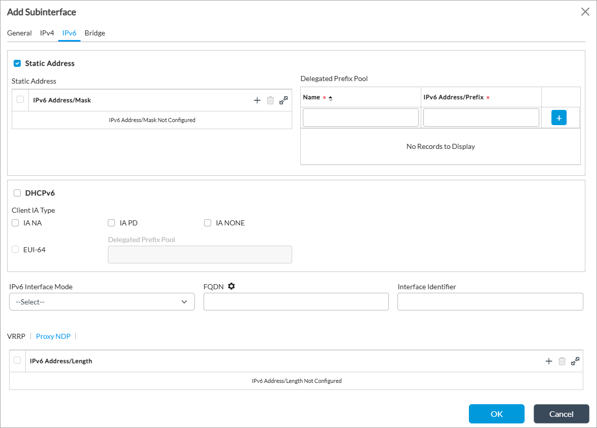
- On the Add Subinterface window, select the IPv6 tab, and then enter information for the following fields.

Field Description Static Address (Group of Fields) Click to use a static IPv6 address for the subinterface. You can configure either an IPv6 static address or use DHCP on the subinterface, but not both. - Static Address
Click the
Add icon, and enter the IPv6 address and prefix length of the static address to use for the subinterface.- Delegated Prefix Pool
Enter the name and IPv6 address of a delegated prefix pool, and then click the Add icon to add the prefix pool.DHCPv6 (Group of Fields) Click to use DHCP to assign an IPv6 address for the subinterface. You can configure either an IPv6 static address or use DHCP on the subinterface, but not both. - Client IA Type
Select the client identity-association (IA) type, which is a collection of addresses assigned to a client:
- IA-NA—Use non-temporary addresses.
- IA-NONE—Do not use a client IA.
- IA-PD—Use prefix delegation.
- EUI-64
Click to use Extended Unique Identifier 64, which allows a host to assign itself a unique 64-bit IPv6 interface identifier. Neighbor Discovery (Group of Fields) - Cache Lifetime (secs)
Enter how long cache entries are retained in the neighbor discovery cache, in seconds.
Range: 0 through 65535 seconds
Default: 30
- Retransmit Interval (secs)
Enter the time interval between retransmissions of neighbor discovery messages, in seconds.
Range: 0 through 65535 seconds
Default: 1
- Route Preference
Enter the route preference value. A lower value gives higher precedence to the route.
Range: 1 through 255
IPv6 Interface Mode Select the IPv6 interface mode:
- Host—Select to configure stateful DHCPv6. This is the default.
- Router—Select to configure stateless automatic address configuration (SLAAC). You must also configure a router advertisement that corresponds to the IPv6 address and prefix length. For more information, see Configure Virtual Routers.
Default: Host
FQDN Enter the fully qualified domain name for the IPv6 subinterface. Interface Identifier Enter the 64-bit interface identifier used to identify a host's network interface. The interface identifier is the second part of an IPv6 unicast or anycast address.
SLA Endpoint Click to make the subinterface an SLA endpoint. When enabled, the subinterface will be used as source address (by appliance on which it is enabled) and destination address (by other SD-WAN appliances) for sending IP-SLA probes for Data-Driven SLA Monitoring. - On the IPv6 tab on the Add Subinterface window, select the VRRP tab in the horizontal menu bar to configure active and standby VRRP devices for high availability (HA).
- Click the Add icon. The Add Subinterface Add VRRP Group window displays.
.png?revision=1)
- On the Add Subinterface Add VRRP Group window, select the General tab, and then enter information for the following fields.
Field Description Group ID (Required) Enter an identifier for the VRRP group.
Range: 1 through 255
Default: None
Address (Required) Enter the IPv6 address of the subinterface on which to configure the VRRP group. Priority Enter the priority to assign to the interface. The interface with the higher or highest priority becomes the VRRP active router.
The priority value that you configure can be reduced by various objects that VRRP tracks, such as interfaces, routes, monitor objects, and HA state. When choosing a priority value, make sure that you account for a worst-case scenario so that the priority never goes below 0. For example, consider a VRRP group configured on interface enet-0/0.0 with priority of 200 and that is tracking interface enet-0/1.0, which has a priority cost of 20. Here, the enet-0/1.0 interface is the tracking object. If the vni-0/1.0 interface goes down, its priority cost is subtracted from the configured priority of 200, and so the current (dynamic) priority becomes (200 – 20), or 180.
Range: 1 through 255
Default: 100Peer Address Enter the address of the peer subinterface. Inherit Configuration Click to have VRRP inherit the properties of another interface.
- Interface Name
Select the name of the subinterface whose configuration properties are to be inherited. - VRRP Group ID
Enter the VRRP group ID of the subinterface whose configuration properties are to be inherited. Preempt Mode Select how the VRRP active router is elected from among the routers in the VRRP group:
- Preempt—When a VRRP active router goes down and a backup router takes over as the active router, the previous active router takes over again as the active router as soon as it comes back up, because it has a higher priority than the active router. This is the default mode.
- No Preempt—When a VRRP active router goes down and a backup router takes over as the active router, the previous active router remains a backup router when it comes back up even though it has a higher priority than the router that has taken over as the active router.
Default: Preempt
Advertisements Threshold Enter the number of VRRP advertisements that the backup router can miss before declaring the active router to be down.
Range: 1 through 15
Default: None
Warmup Interval Enter how long the interface waits, in seconds, before determining which VRRP router is the active router and which is the backup.
Range: 1 through 3600 seconds
Virtual Address (Required) Configure a virtual address for the subinterface. - IP Address
Enter the virtual IP address or addresses to include in the VRRP group, and then click the Add icon.Fast Interval For VRRP Version 3 only, enter how often the active and backup routers exchange VRRP advertisement messages, in milliseconds.
Range: 10 through 50000 milliseconds
Virtual Link Local Address Enter an address to explicitly configure a link local address for the VRRP group. HA Standby Priority Cost Enter the value to subtract from the priority when the interchassis HA state of the VOS device changes from active to standby.
Range: 1 through 254
Default: 100Accept Data Click to have the interface accept data that it receives. Otherwise, the data is routed to another interface. - On the Add Subinterface Add VRRP Group window, select the Track tab, and then enter information for the following fields.

Field Description Priority Hold Time Enter the virtual router priority hold time, in seconds.
Range: 0 through 3600 seconds
Default: None
Interface (Tab) - Name (Required)
Select the primary interface on the active router in the VRRP group. - Priority Cost
Enter the cost for the interface. The router with the highest priority in the VRRP group is or becomes the active router.
Range: 1 through 254
Default: 100
Add iconClick to add the interface to the VRRP group. Routes (Tab) 
- Prefix (Required)
Enter the route prefix. - Routing Instance (Required)
Select the routing instance. - Priority Cost (Required)
Enter the cost for the interface. The router with the highest priority in the VRRP group is or becomes the active router.
Range: 1 through 254
Default: 100
 Add icon
Click to add the interface. Monitors (Tab) 
- Name (Required)
Select the primary interface on the active router in the VRRP group. - Priority Cost
Enter the cost for the interface. The router with the highest priority in the VRRP group is or becomes the active router.
Range: 1 through 254
Default: 100
 Add icon
Click to add the monitor to the VRRP group. - Click OK.
- On the IPv6 tab on the Add Subinterface window, select the Proxy NDP tab in the horizontal menu bar to configure proxy NDP. To use proxy NDP, you configure a set of IPv6 subnet prefixes or prefix ranges to which proxy NDP on the VOS device responds if no NDP entry for an IP address is available. Proxy NDP allows a VOS device to respond to NDP requests for IP addresses configured in NAT pools that are both within and outside of the interface’s subnet. Proxy NDP provides local responses, allowing a VOS device to reduce the amount of broadcast traffic over Layer 2 networks (such as EVPN) across SD-WAN and VXLAN. IPv6 NAT supports proxy NDP for Network Prefix Translation version 6 (NPTv6).
- Click the Add icon to configure proxy NDP on the subinterface. To use proxy NDP, you configure a set of IPv6 subnet prefixes or prefix ranges to which proxy NDP on the VOS device responds if no NDP entry for an IP address is available. Proxy NDP allows a VOS device to respond to NDP requests for IP addresses configured in NAT pools that are both within and outside of the interface’s subnet. Proxy NDP provides local responses, allowing a VOS device to reduce the amount of broadcast traffic over Layer 2 networks (such as EVPN) across SD-WAN and VXLAN. IPv6 NAT supports proxy NDP for Network Prefix Translation version 6 (NPTv6).
Click the Add icon to configure IPv6 addresses and prefix lengths for proxy NDP. The IP address range or subnet that you configure for proxy NDP does not need to be within the interface’s subnet. You must ensure that the requestor or the peer is in same subnet as the interface IP address.
- Select the Bridge tab in the Add Subinterface window, and enter information for the following fields.

Field Description Interface Mode Select the interface mode:
- Access
- Trunk
dot1x Click to enable 801.1X on the subinterface. VLAN ID For the Access interface mode, enter the VLAN ID for the subinterface.
Range: 1 through 4094
VLAN ID List For the Trunk interface mode, enter the VLAN ID list for the subinterface.
Range: 1 through 4094
- In the Add Enet Interface window, in the Subinterfaces tab, click Aggregate Member to using the Link Aggregation Control Protocol (LACP) to bundle severl physical links to form a single logical link. LACP allows a network device to negotiate an automatic bundling of links by sending LACP packets to their peer, a directly connected device that also implements LACP. Enter information for the following fields.

Field Description Interface (Required) Select the interface name. LACP Priority Enter an LACP priority number.
Range: 1 through 65535
Default: 127
- Click OK to complete configuration of the LAN Ethernet interface.
Configure Aggregated Ethernet Layer 2 Interfaces
For Releases 23.1.2 and later.
You can group multiple physical Ethernet ports together as a single virtual, logical interface. The combined interface is an aggregated Ethernet Layer 2 interface, also referred to as a Layer 2 Link Aggregation Group (LAG), L2 EtherChannel, or bridged AE interface.
To configure an aggregated Ethernet Layer 2 interface:
- In Director view, select the Workflows tab in the top menu bar.
- Select Templates > Templates in the horizontal menu bar.
- Select an organization in the Organization field.
- Select the SD-WAN tab. The screen displays the templates that are already configured.
- Select a template to edit. The interface configuration wizard displays workflow step 1, Basic.
- Click Next or select workflow step 2, Interfaces. The screen displays a graphic showing the ports on the device.

- To configure an aggregated Ethernet Layer 2 interface, click the port number, and then select AE L2 in the popup window.

- The Device Port Configuration screen displays workflow step 1, AE. Enter information for the following fields.

Field Description AE Number (Required) Enter a number for the aggregated Ethernet interface. Aggregated Ethernet interface names start with ae. Description Enter a text description for the aggregated Ethernet interface. Tags Enter text strings that describe the aggregated Ethernet interface. A tag is an alphanumeric text descriptor with no spaces or special characters. You can specify multiple tags added for the same object. The tags are used for searching the objects. Native VLAN ID Enter the native VLAN ID for the aggregated Ethernet interface.
Range: 1 through 4094
System ID/MAC Enter a user-defined system identifier for the device, which must be exactly 6 octets (for example, 20:10:00:00:00:03). Chassis ID Enter a chassis ID number. The chassis ID is combined with the locally-assigned port ID to determine a unique Actor_Port number that is sent in the Link Aggregation Control Protocol Data Unit (LACPDU) frame. This prevents conflicts between multihomed appliances in an EVPN environment.
Range: 1 through 7
Default: None
Admin Key Enter an administrative key number. The administrative key, in conjunction with the system ID, enables ports from two separate VOS devices to behave as if they are part of the same aggregate interface. Selected Member Ports Select the physical ports to be members of the Aggregated Ethernet interface. You can enter only unassigned port numbers. A single port number can be separated with a comma (,) or a range of port numbers can be entered separated with a hyphen (-). For example, 1, 4-6. LACP (Group of Fields) Click the slider bar to select the LACP mode.- LACP Mode
Select the LACP mode. The LACP mode controls how the interface negotiates with the link. You can select one of two modes:
- Active—The interface actively transmits LACP PDUs on the configured links.
- Passive—The interface does not actively transmit LACP PDUs, but does send responses when it receives LACP PDUs from an active interface.
- LACP Timer
Select the LACP timer. The LACP timer determines the frequency of LACP packet transmissions. You can select one of two intervals:
- Slow—Transmits packets every second for rapid failure detection.
- Fast—Transmits packets every 30 seconds to minimize overhead.
- Click Next or select step 2, L2 Configuration.
- Enter information for the following fields.
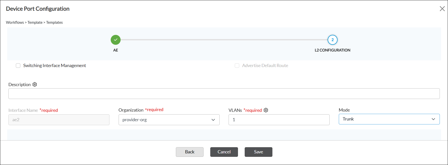
Field Description Switching Interface Management Click to configure Layer 2 switching interfaces on VOS devices. - Advertise Default Route
Click to control if a device originates and advertises a default route to its neighbors. Description Enter a text description for the Layer 2 interface. Interface Name (Required) The Interface Name field is auto-populated and greyed out. Organization (Required) Select the organization to which the interface belongs. VLANs (Required) Enter the VLAN ID to associate with the Layer 2 interface. Use the same VLAN ID for all the Layer 2 interfaces that are members of the aggregated Ethernet interface. Mode Select the Layer 2 interface mode:
- Access
- Trunk
- Click Save.
- Click Done. The screen shows the configured interface on the AE Interfaces tab (here, ae2).

Configure Aggregated Ethernet LAN Interfaces
For Releases 23.1.2 and later.
An aggregated Ethernet LAN interface is a virtual interface that combines multiple physical Ethernet links into a single, logical high-speed connection.
To configure an aggregated Ethernet LAN interface:
- In Director view, select the Workflows tab in the top menu bar.
- Select Templates > Templates in the horizontal menu bar.
- Select an organization in the Organization field.
- Select the SD-WAN tab. The screen displays the templates that are already configured.
- Select a template to edit. The interface configuration wizard displays workflow step 1, Basic.
- In the configuration wizard, select workflow step 2, Interfaces. The screen displays a graphic showing the ports on the device.
- Click the port number, and then select AE LAN in the popup window.

- The Device Port Configuration screen displays workflow step 1, AE. Enter information for the following fields.

Field Description AE Number (Required) Enter a number for the aggregated Ethernet interface. Aggregated Ethernet interface names start with ae. Description Enter a text description for the aggregated Ethernet interface. Tags Enter text strings that describe the aggregated Ethernet interface. A tag is an alphanumeric text descriptor with no spaces or special characters. You can specify multiple tags for the same object. The tags are used for searching the objects. Native VLAN ID Enter the native VLAN ID for the aggregated Ethernet interface.
Range: 1 through 4094
System ID/MAC Enter a user-defined system identifier for the device, which must be exactly 6 octets (for example, 20:10:00:00:00:03). Chassis ID Enter a chassis ID number. The chassis ID is combined with the locally-assigned port ID to determine a unique Actor_Port number that is sent in the LACPDU frame.
Range: 1 through 7
Default: None
Admin Key Enter an administrative key number. The administrative key, in conjunction with the system ID, enables ports from two separate VOS devices to behave as if they are part of the same aggregate interface. Selected Member Ports Select the physical port numbers to be members of the aggregated Ethernet interface. You can enter only unassigned port numbers. A single port number can be separated with a comma (,) or a range of port numbers can be entered separated with a hyphen (-). For example, 1, 4-6. LACP (Group of Fields) Click the toggle to enable the Link Aggregation Control Protocol (LACP) for the aggregated Ethernet interfaces. - LACP Mode
Select the LACP mode:
- Active—The interface actively transmits LACP PDUs on the configured links.
- Passive—The interface does not actively transmit LACP PDUs, but does send responses when it receives LACP PDUs from an active interface.
- LACP Timer
Select the LACP timer:
- Slow
- Fast
- Click Next or select workflow step 2, LAN Configuration, and enter information for the following fields.

Field Description VLAN ID (Required) Enter the VLAN identifier for the aggregated Ethernet LAN interface. Network Name (Required) Select the LAN network to which the interface connects. Description Enter a text description for the aggregated Ethernet LAN interface. Organization (Required) Select the organization to which the aggregated Ethernet interface belongs. Routing Instances (Required) Select the organization's routing instance with which the aggregated Ethernet LAN interface is associated. Zones Select the zone to which the aggregated Ethernet interface belongs. If you do not select a zone, the interface is automatically associated with a zone based on the aggregated Ethernet LAN network name. IPv4 Use IPv4 addressing on the aggregated Ethernet LAN interface.
- Static—Use static IP addresses. When you select Static, a bind-data variable for the interface's static address is automatically generated in the template.
- DHCP—Use DHCP to obtain an IP address.
IPv6 Use IPv6 addressing on the aggregated Ethernet LAN interface.
- Static—Use static IP addresses. When you select Static, a bind-data variable for the interface's static address is automatically generated in the template.
- DHCP—Use DHCP to obtain an IP address.
Enable DHCP Server Click to enable DHCP server. - DHCP Options Profile
Select the DHCP options profile. DHCP Relay Forwarding Addresses Enter the IP address of the DHCP server, and then click the  Add icon.
 - Click Save.
- Click Done. The screen shows the configured interface on the AE Interfaces tab (here, ae1).

Configure IRB Interfaces
For information about configuring IRB interfaces, see Configure IRB Interfaces in Configuring Layer 2 Forwarding.
Configure T1/E1 Interfaces
You can configure T1/E1 interfaces on VOS devices that can operate in T1 networks (in North America) or E1 networks (rest of the world). T1/E1 interfaces support line coding, framing, and diagnostics options that you can use to verify and troubleshoot connectivity issues. T1/E1 interfaces facilitate data and control plane functionality, such as a WAN interface-level control plane, and they support encapsulation and decapsulation (PPP, Frame Relay, and high-level data link control [HDLC]).
For Releases 22.1.1 and later, you can specify the cable length for each T1 interface link, either short or long haul, which then configures the appropriate transmission waveform on T1 interface.
To configure a T1/E1 interface:
- In Director view:
- Select the Administration tab in the top menu bar.
- Select Appliances in the left menu bar.
- Select a device name in the main panel. The view changes to Appliance view.
- Select the Configuration tab in the top menu bar.
- Select Networking > Interfaces in the left menu bar.
- Select the T1/E1 tab in the horizontal menu bar.

- Click the Add icon. In the Add T1/E1 Interface popup window, enter information for the following fields.

Field Description T1 Click to configure a T1 interface. E1 Click to configure an E1 interface. Interface (Required) Enter the slot and port numbers for the T1/E1 interface. The slot number must be 0. The port number can be a number from 0 through 3.
Disable Click to not activate the T1/E1 interface after you configure it. Mirror Interface Click to create a copy of the interface. Multilink (For Releases 21.2.1 and later.) Click to configure a multilink interface and then select the multilink Frame Relay or multilink PPP interface type. For more information, see Step 6 below.

Description Enter a text description for the T1/E1 interface. It can be a text string up to 255 characters. Channel Group (Required) Enter the channel group number. For Versa CSG appliances, channel group must be 0. Cable Length (For Releases 22.1.1 and later.) For T1 interfaces, select the link cable length:
- Long—Use long haul. Then select the attenuation:
- 0 dB
- –7.5 dB (Default)
- –15 dB
- –22.5 dB
- Short—Use short haul. Then select the length:
- 110 ft. (Default)
- 220 ft.
- 330 ft.
- 440 ft.
- 550 ft.
- 660 ft.
Clock Source (Required) Select the clock source:
- External
- Internal
Time Slot Begin (Required) Enter a starting number for the interface time slots.
Range: 0 through 31
Default: None
Time Slot End (Required) Enter an ending number for the interface time slots.
Range: 0 through 31
Default: None
Encapsulation (Group of Fields)
You must configure an encapsulation. - Frame Relay
Click to use Frame Relay encapsulation. For Frame Relay, you can configure subinterfaces with multiple units. - Lowest DLCI Channel Number
Enter the lowest data link connection identifier (DLCI) channel number allowed. - Total Number of DLCI Channels
Enter the total number of DLCI channels that can be created on the interface. - Maximum Receive SDU Size
Enter the maximum receive SDU size, in bytes. - Maximum Transmit SDU Size
Enter the maximum transmit SDU size, in bytes. - HDLC
Click to use HDLC encapsulation. Subinterface with only unit 0 is allowed in HDLC encapsulation. - Framing
For a T1 interface, select the encapsulation HDLC framing type:
- T1 ESF—T1 extended superframe
For an E1 interface, select the encapsulation HDLC framing type:
- E1 CRC4
- E1 No CRC4
- E1 Unframed
- PPP
(Default) Click to use PPP encapsulation, to encapsulate network layer protocol information over point-to-point links. With PPP encapsulation, you can configure subinterfaces with only unit 0.
Select the authentication protocol:
- None—No authentication
- CHAP—Challenge handshake authentication protocol (CHAP)
- PAP—Password authentication protocol (PAP)
- Authentication Protocol
For PPP encapsulation, select the authentication protocol:
- CHAP—Challenge handshake authentication protocol
- None—No authentication
- PAP—Password authentication protocol
- Long—Use long haul. Then select the attenuation:
- Click the ML T1/E1 Interface tab to configure a multilink T1/E1 interface. Enter information for the following fields.

Field Description Interface (Required) Enter the slot and port numbers for the multilink T1/E1 interface. The slot number must be 0. The port number can be 0 or 1. Disable Click to not activate the multilink T1/E1 interface after you configure it. Mirror Interface Click to create a copy of the multilink T1/E1 interface. Description Enter a text description for the multilink T1/E1 interface. It can be a text string up to 255 characters. Channel Group Enter the channel group number. For Versa CSG appliances, the channel group number must be 0. Clock Source Select the clock source: - External
- Internal
Time Slot Begin Enter a starting number for the multilink T1/E1 interface time slot.
Range: 0 through 23 (for T1 interfaces); 0 through 31 (for E1 interfaces)
Time Slot End Enter an ending number for the multilink T1/E1 interface time slot.
Range: 0 through 23 (for T1 interfaces); 0 through 31 (for E1 interfaces)Cable Length (For Releases 22.1.1 and later.) Select the link cable length:
Long—Use long haul. Then select the attenuation:- 0 dB
- –7.5 dB
- –15 dB
- –22.5 dB
- 110 ft.
- 220 ft.
- 330 ft.
- 440 ft.
- 550 ft.
- 660 ft.
Encapsulation (Group of Fields) - Multilink Frame Relay
Click to use multilink frame relay encapsulation. In multilink frame relay, you can configure subinterfaces with multiple units. - Multilink PPP
Click to use multilink PPP encapsulation, to encapsulate network layer protocol information over point-to-point links. For multilink PPP encapsulation, you can configure subinterfaces with unit 0 only. - Authentication Protocol
For multilink PPP encapsulation, select the authentication protocol:
- CHAP—Challenge handshake authentication protocol
- None—No authentication
- PAP—Password authentication protocol
- Maximum Received Reconstructed Unit
Enter the maximum received reconstructed unit, in bytes. - In the Subinterfaces table, click the Add icon. In the Add Subinterface popup window, enter information for the following fields.

Field Description Unit (Required) Enter a unit number for the subinterface. Disable Click to not activate the subinterface after you configure it. Description Enter a text description for the subinterface. It can be a text string up to 255 characters. Interface DLCI (For Frame Relay encapsulation only.) Enter the Frame Relay data link connection identifier.
Range: 17 through 1000
Default: None
MTU Enter the size, in bytes, of the largest protocol data unit that the subinterface can receive or transmit.
Range: 72 through 9000 bytes
Default: None
HA Interface Mode Select the HA interface mode:
- Normal
- Redundancy
Bandwidth (Group of Fields) - Uplink (Kbps)
Enter the bandwidth available on the subinterface for uploading data, in kilobits per second (Kbps).
Range: 1 through 10000000 Kbps
Default: None
- Downlink (Kbps)
Enter the bandwidth available on the subinterface for downloading data, in kilobits per second (Kbps).
Range: 1 through 10000000 Kbps
Default: None
- IPv6 Interface Mode
Select the IPv6 interface mode:
- Host—This is the default. Use to configure stateful DHCPv6.
- Router—Select to configure stateless automatic address configuration (SLAAC). You must also configure a router advertisement that corresponds to the IPv6 address and prefix length. For more information, see Configure Virtual Routers.
- FQDN
Enter the fully qualified domain name for the IPv6 subinterface. Bridge (Tab) - Interface Mode
Select the interface mode:
- Access
- Trunk
- VLAN ID
Enter the VLAN ID for the subinterface. - VLAN ID List
Enter the VLAN ID list for the subinterface. - Select the IPv4 tab, then enter information for the following fields.

Field Description Static Address
Click to use a static IPv4 address for the subinterface. IP Address/Mask
Enter the IP address and prefix length, and then click the Add icon.DHCPv4
Click to use DHCP to assign an IPv4 address for the subinterface. - Route Preference
Enter the preference for the traffic route. A lower value indicates a higher preference. - Vendor Class Identifier
Enter the vendor class identifier. - Disable Broadcast Flag
Click to disable broadcast on the subinterface's network. - Reachability Monitor
- Enable ICMP
Click to enable ICMP on the subinterface. - Interval
Enter the time interval after which ICMP reports error messages. - Threshold
Enter the maximum number of ICMP error messages to report. FQDN
Enter the fully qualified domain name for the IPv4 subinterface. Directed Broadcast
Click to enable directed broadcast, which sends broadcast packets targeted at hosts in a specified subnet. SLA Endpoint
Click to make this subinterface an SLA endpoint. When enabled, the subinterface will be used as source address (by appliance on which it is enabled) and destination address (by other SD-WAN appliances) for sending IP-SLA probes for Data-Driven SLA Monitoring. Static ARP (Tab)
Select to configure static ARP mapping. - Subnet Address/Mask
Select the subnet address and mask. - Host IP Address
Enter the IP address of the host. - MAC Address
Enter the MAC address of the host. - Select the VRRP tab to configure an active and a standby VRRP device for high availability (HA) mode. For more information, see Step 13 through 15 in Configure LAN Ethernet Interfaces.
- Select the IPv6 tab, then enter information for the following fields.

Field Description Static Address
Click to use a static IPv6 address for the subinterface. Delegated Prefix Pool (Group of Fields)
- Name
Enter the name and IP address of the delegated prefix pool. - IPv6 Address/Mask
Enter the IPv6 address and prefix length, then click the Add icon.DHCPv6 (Group of Fields) - Client IA Type
Select the client identity association type:
- EUI 64
- IA-NA
- IA-NONE
- IA-PD
- Delegated Prefix Pool
Enter the name and IP address of the delegated prefix pool. IPv6 Interface Mode
Select the IPv6 interface mode:
- Host—This is the default. Use to configure stateful DHCPv6.
- Router—Select to configure stateless automatic address configuration (SLAAC). You must also configure a router advertisement that corresponds to the IPv6 address and prefix length. For more information, see Configure Virtual Routers.
FQDN
Enter the fully qualified domain name for the IPv6 subinterface. Interface Identifier
Enter the 64-bit interface identifier used to identify a host's network interface. The interface identifier is the second part of an IPv6 unicast or anycast address. SLA Endpoint Click to make this subinterface an SLA endpoint. When enabled, the subinterface will be used as source address (by appliance on which it is enabled) and destination address (by other SD-WAN appliances) for sending IP-SLA probes for Data-Driven SLA Monitoring. VRRP Click the Add icon to configure an active and a standby VRRP device for high availability (HA) mode. For more information, see Step 13 through 15 in Configure LAN Ethernet Interfaces. -
Select the Bridge tab, then enter information for the following fields.

Field Description Interface Mode Select the interface mode:
- Access
- Trunk
dot1x Click to enable 801.1X on the subinterface. VLAN ID For the Access interface mode, enter the VLAN ID for the subinterface.
Range: 1 through 4094
VLAN ID List For the Trunk interface mode, enter the VLAN ID list for the subinterface.
Range: 1 through 4094
- Click OK.
Configure the T1/E1 Authentication Protocol
For Releases 21.2.1 and later.
You can configure the T1/E1 authentication protocol and associated password using the Password Authentication Protocol (PAP) and Challenge Handshake Authentication Protocol (CHAP) authentication methods. PAP and CHAP are used by PPP to authenticate its peer. When a PPP connection is established, each end can request that the other end authenticate itself. PAP authentication uses a clear text-based username and password to authenticate the PPP peer. With CHAP authentication, the authenticator sends a randomly generated challenge string to the client with its hostname. The client uses the hostname to look up the appropriate secret, combines it with the challenge, and encrypts the string using a one-way hashing function. The client returns the result to the server along with the client's hostname. The server then performs the same computation and acknowledges the client if it arrives at the same result.
To configure T1/E1 authentication protocol:
- In Director view:
- Select the Administration tab in the top menu bar.
- Select Appliances in the left menu bar.
- Select a device name in the main panel. The view changes to Appliance view.
- Select the Configuration tab in the top menu bar.
- Select Networking > T1/E1 Authentication in the left menu bar.

- In the T1/E1 Authentication pane, click the
 Edit icon. In the Edit T1/E1 Authentication popup window, enter information for the following fields.
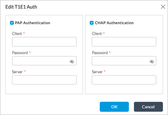
Field Description Client (Required) Enter client username. The username is used as a reference for the PAP and CHAP password database. Password (Required) Enter the password to use to authenticate the server connection request. Server (Required) Enter the username to use to authenticate the server connection request. - Click OK.
Configure Tunnel Interfaces
You use tunnel interfaces to configure an IPsec tunnel and high availability (HA) between two VOS devices. For SD-WAN networks, you create multiple tunnel interfaces to connect a branch with a Controller device.
Tunnel interfaces are named with the prefix tvi, for tunnel virtual interface.
For information about tunnel interface numbering, see Understand SD-WAN Interface Numbering.
To configure a tunnel interface:
- In Director view:
- Select the Configuration tab in the top menu bar.
- Select Templates > Device Templates in the horizontal menu bar.
- Select an organization in the left menu bar.
- Select a Controller in the main pane. The view changes to Appliance view.
- Select the Configuration tab in the top menu bar.
- Select Networking > Interfaces in the left menu bar.
- Select the Tunnel tab in the horizontal menu bar.

- Click the Add icon. In the Add Tunnel Interface popup window, select the Tunnel tab and enter information for the following fields.

Field Description Interface (Required) Enter the port and slot numbers for the tunnel (tvi) interface. Disable Click to not activate the tunnel interface after it is configured. Mirror Interface Click to have the tunnel interface be a mirror interface. Description Enter a text description for the tunnel interface. It can be a string up to 255 characters. MTU Enter the maximum transmission unit size, in bytes, of largest protocol data unit that the port can receive or transmit.
Range: 72 through 9000 bytesMode Select the tunnel mode:
- IPsec—Use for IPsec.
- Redundancy—Use for HA.
Tunnel Type Select the tunnel type:
- Ethernet over GRE—Use to leverage existing low-end residential gateways to provide mobility services to mobile nodes.
- (For Releases 22.1.1 and later.) IPv6 IPIP tunnel—IPv4 tunnel over IPv6 transport.
Note: To use static Mapping of Address and Port with Encapsulation (MAP-E), configure the CE with an IPv6 IPIP tunnel. IPv4 packets are sent through this tunnel between the CE and a border relay (BR) device. For MAP-E, Versa supports network address port translation (NAPT), and TCP, UDP, and ICMP protocols. To steer LAN-side packets to the tunnel, define a CGNAT rule under the tenant organization using NAT mode NAPT-44. For information about configuring CGNAT rules, see Configure CGNAT. - Paired.
- Point-to-multipoint clear-text SD-WAN tunnel.
- Point-to-multipoint GRE tunnel—Generic Routing Encapsulation tunnels encapsulate a variety of network layer protocols inside point-to-point links. GRE tunnels are used to send packets from one network to another over the internet or an insecure network.
- Point-to-multipoint IPsec tunnel—An IPsec tunnel that helps protect site-to-site traffic between networks.
- Point-to-multipoint secure SD-WAN tunnel.
- Point-to-multipoint VXLAN tunnel—Virtual Extensible LAN tunnels connect VXLAN tunnel endpoints (VTEPs). The endpoints can be either virtual or physical switch ports.
- Point-to-point GRE tunnel.
- Point-to-point IPsec tunnel.
- Point-to-point V6 GRE tunnel.
- PPPoE—Point-to-Point Protocol over Ethernet encapsulates PPP frames inside Ethernet frames. PPPoE is used with DSL services in which individual users connect to a DSL modem over Ethernet.
Multihoming (Group of Fields) - Active Mode
Select the multihoming mode, either Active or Standby. - ESI
Enter an Ethernet segment identifier (ESI), which is a 10-octet, non-zero value that is unique across the network. - In the Subinterfaces table, click the Add icon or select an existing subinterface.
- In the Edit Subinterface popup window, under the General tab, enter information for the following fields.

Field Description Unit (Required) Enter the subinterface number. Description Enter a text description for the subinterface. It can be a string up to 255 characters. VLAN ID Enter the VLAN ID for the subinterface. Disable Click to not activate the tunnel interface after it is configured. MPLS Select to enable MPLS on the subinterface. Bandwidth (Tab) Allows you to specify the bandwidth available on a link to upload and download data. This information is used in computing adaptive traffic shaping. - Uplink (Kbps)
Enter the bandwidth available on the link for uploading data, in kilobits per second (Kbps).
Range: 1 through 10000000 Kbps
Default: None
- Downlink (Kbps)
Enter the bandwidth available on the link for downloading data, in kilobits per second (Kbps).
Range: 1 through 10000000 Kbps
Default: None
- Click the IPv4 tab.
- In the Static Address table, click the Add icon, then enter an IPv4 address and subnet mask.

- Click the SLA Endpoint box to make the subinterface an SLA endpoint. When enabled, the subinterface will be used as source address (by appliance on which it is enabled) and destination address (by other SD-WAN appliances) for sending IP-SLA probes for Data-Driven SLA Monitoring.
- Click the IPv6 tab, then enter information for the following fields.

Field Description Static Address Click to add a static IPv6 address, then click the Add icon and enter an IPv6 address and subnet mask. DHCPv6 (Group of Fields) Click to add a DHCPv6 address. - Client IA Type (Group of Fields)
- IA NA
Click to assign a global Identity Association Nontemporary Address on a WAN link. - IA PD
IA for Prefix Designation to request a block of IPv6 addresses from a DHCP server.
Click to assign
refers to the DHCP Unique Identifier (DUID) to obtain IP addresses and configuration information from a DHCPv6 server. The DUID, along with an Identity Association Identifier (IAID) for a specific interface, forms the client ID
- Delegated Prefix Pool
(For IA PD only.) Enter the name of the delegated prefix pool. - EUI 64
Click to automatically generate a unique 64-bit Interface ID for an IPv6 address. IPv6 Interface Mode Select the IPv6 interface mode:
- Host—This is the default. Use to configure stateful DHCPv6.
- Router—Select to configure stateless automatic address configuration (SLAAC). You must also configure a router advertisement that corresponds to the IPv6 address and prefix length. For more information, see Configure Virtual Routers
Interface Identifier If you configure the subinterface using a static IPv6 address, enter the interface identifier, which is a valid IPv6 address. SLA Endpoint Click to make the IPv6 subinterface an SLA endpoint. When enabled, the subinterface will be used as source address (by appliance on which it is enabled) and destination address (by other SD-WAN appliances) for sending IP-SLA probes for Data-Driven SLA Monitoring. - Click OK.
- Select the Pseudo Tunnel tab, and then enter information for the following fields.
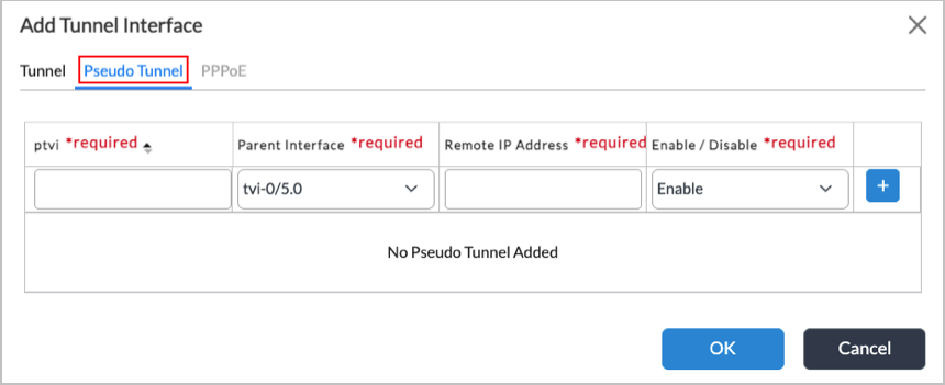
Field Description Name (Required) Enter a number to identify the pseudo tunnel interface. Parent Interface (Required) Select the parent tunnel interface to use for the pseudo tunnel. Remote IP Address (Required) Enter the IP address of the remote endpoint of the pseudo tunnel Enable/Disable (Required) Select to enable or disable the pseudo tunnel interface.  Add icon
Click the add icon to add the pseudo tunnel. - If you selected the PPPoE tunnel type, click the PPoE tab, and then enter information for the following fields.

Field Description VNI Interface Select a VNI interface. Preferred IP Enter the preferred source IP address for the tunnel. Service Name Enter the service name. Access Concentrator Enter the name of the access concentrator. The access concentrator name on both the client and the server must be the same to establish the PPPoE session. Username Enter the username. Password Enter the password. ICP Echo Interval Enter how often to send ICP echo requests to peer, in seconds. ICP Echo Failure Enter the number of ICP echo requests to send without receiving a valid ICP echo reply before assuming that the peer is unreachable (dead).
Route Preference Enter the route preference to use when installing the default route. - Click OK.
Configure GRE Tunnel Interfaces
You can configure four types of GRE tunnels.
- Point-to-point GRE
- Point-to-point IPv6 GRE
- Ethernet over GRE
- Point-to-multi-point GRE (Release 22.1.4 Service Release dated 2024/12/21 or later)
The GRE tunnels have the following common input parameters:
- Source—IPv4 (point-to-point GRE, Ethernet over GRE, point-to-multi-point GRE) or IPv6 (point-to-point IPv6 GRE) address that must be configured on any of the local VNI/TVI interfaces. This parameter uses the source IP in the IPv4 header and adds as GRE encapsulation. The remote end sends packets back to this IP, so that if the packet is not configured in any local interface, then the packet does not terminate in VOS.
- Destination—IPv4 (point-to-point GRE, Ethernet over GRE) or IPv6 (point-to-point IPv6 GRE) address of the remote tunnel endpoint that can be any device supporting the GRE tunnel.
- Routing instance—(point-to-point GRE, Ethernet over GRE, point-to-point IPv6 GRE) Routing instance in which the VNI/TVI interface resides, using its IP address as a source in the GRE tunnel configuration.
A TVI interface applies in the routing instance and in the organization.
GRE and IPv6 GRE tunnels support only one subinterface, unit 0, and Ethernet-over-GRE tunnels can have subinterfaces with VLAN IDs from 0 to 4095. Subinterfaces can have either IPv4 or IPv6 addresses.
Static NHRP Mapping
For Release 22.1.4 Service Release dated 2024-12-23 or later.
You can map the loopback IP address of a remote router with the IP address of a remote nonbroadcast multiaccess (NBMA) network transport interface so the local device can communicate directly with remote devices over the NBMA network.
VOS automatically creates a GRE tunnel to the destination IP address using the NBMA IP address as the destination transport IP address. It also creates a host route for the destination IP address in the static NHRP map with the GRE tunnel as the nexthop interface. Accordingly, all traffic through this nexthop IP address may use the GRE tunnel. L3VPN data packets through this nexthop IP address use MPLS-over-GRE encapsulation over this GRE tunnel.
You configure static NHRP mapping when you create a GRE tunnel interface, as shown below.
Configure a GRE Tunnel
To configure a GRE tunnel:
- In Director view:
- Select the Administration tab in the top menu bar.
- Select Appliances in the left menu bar.
- Select a device in the main pane. The view changes to Appliance view.
- Select the Configuration tab in the top menu bar.
- Select Networking > Interfaces in the left menu bar.
- Select the Tunnel tab in the horizontal menu bar.
- Click the Add icon. In the Add Tunnel Interface popup window, select the Tunnel tab and enter information for the following fields.

Field Description Interface Enter the port and slot numbers for the tunnel (tvi) interface. Description Enter a text description for the tunnel interface. It can be a string up to 255 characters. Disable Click to not activate the tunnel interface after it is configured. Mirror Interface Click to enable flow mirroring on the interface. Note that when you configure an interface as a mirror interface, the Subinterfaces fields are grayed out. MTU Enter the maximum transmission unit size, in bytes, of largest protocol data unit that the port can receive or transmit.
Range: 256 through 9000 bytesMode Select the tunnel mode:
- IPsec—Use for IPsec
- Redundancy—Use for HA
Tunnel Type Select the tunnel type:
- Ethernet over GRE
- Point-to-multi-point GRE
- Point-to-point GRE
- Point-to-point V6 GRE
GRE Key Enter a GRE key that uniquely identifies and differentiates between multiple GRE tunnels that share the same source and destination addresses.
Source Enter the source transport IP address of the tunnel on the local device you are using to configure the remote devices. NHRP Map (Group of Fields) The Next Hop Routing Protocol (NHRP) allows systems on a nonbroadcast multiaccess (NBMA) network to learn the physical transport address of other systems on the network so they can communicate directly. NHRP does this by mapping a tunnel interface's IP address to a next-hop router's physical transport address.
- IP Address
Enter the loopback IP address of the remote router. - NBMA IP
Enter the IP address of the remote nonbroadcast multiaccess (NBMA) network transport interface. - Add icon
Click to create the NHRP map. You can configure multiple NHRP maps. Routing Instance Select the routing instance in which the tunnel interface resides.
- In the Subinterfaces table, select an existing subinterface. then click the IPv4 tab.
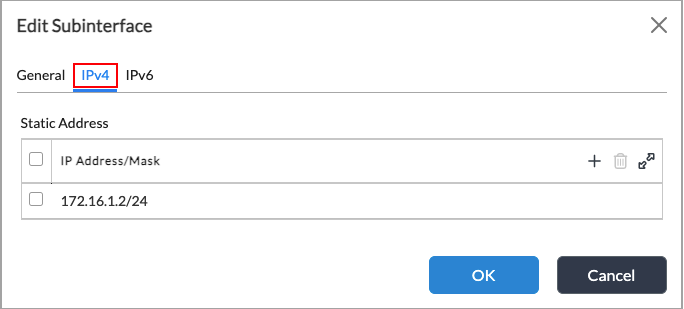
- Click the Add icon. Under Static Address, enter the IP address and mask for the subinterface.
- Click OK.
Configure CSM Interfaces
For information about configuring CSM interfaces, see Configure CSM Interfaces.
Configure DSL Interfaces
You can configure digital subscriber line (DSL) WAN interfaces on VOS devices. These interfaces can operate in asymmetric digital subscriber line (ADSL2+) mode and very high speed digital subscriber line (VDSL2) mode networks. ADSL2+ and VDSL2 interfaces support a single WAN interface, allowing you to connect to ADSL2 and VDSL2 networks and providing high-speed digital data transmission between customer premises equipment (CPE) and DSL access multiplexers (DSLAMs). You can use these interfaces to upgrade existing xDSL infrastructure.
VDSL2 interfaces support triple-play services, such as voice, video, data, and high-definition television (HDTV).
You can deploy VOS SD-WAN, security, routing, and network performance management features onADSL2+ and VDSL2 interfaces.
ADSL2+ and VDSL2 interfaces support the following encapsulation types:
- Point-to-Point Protocol over Ethernet (PPPoE)
- Point-to-Point Protocol over Ethernet over ATM (PPPoEoA)
- VLAN
You can configure ATM, LLC, or VC-MUX-based transparent bridging for the NIC with the virtual path identifier (VPI)/virtual channel identifier (VCI) configuration option. VOS network packet processing includes a full set of Layer 2, Layer 3, and Layer 4 to Layer 7 functions, including VLAN and other methods to separate traffic.
To configure a DSL interface:
- In Director view:
- Select the Administration tab in the top menu bar.
- Select Appliances in the left menu bar.
- Select a device name in the main panel. The view changes to Appliance view.
- Select the Configuration tab in the top menu bar.
- Select Networking > Interfaces in the left menu bar.
- Select the DSL tab in the horizontal menu bar.
- Click the Add icon. In the Add DSL Interface popup window, select the Tunnel tab and enter information for the following fields.

Field Description Interface (Required) Enter the slot and port numbers for the DSL interface. Disable Click to not activate the DSL interface after you configure it. Description Enter a text description for the T1 interface. It can be a text string up to 255 characters. Enable NSH Header Click to enable network service header–based service chaining. Act as a IETF SFC Service Click to have the interface perform IETF service function chaining with no service function forwarder configuration. MTU Enter the size, in bytes, of the largest protocol data unit that the interface can receive or transmit.
Range: 72 through 9000 bytes
- In the Subinterfaces section, and click the Add icon to add a subinterface. The Add Subinterface screen displays.
- In the General tab, enter information for the following fields.

Field Description Unit (Required) Enter a unit number for the subinterface. Disable Click to not activate the subinterface after you configure it. Description Enter a text description for the subinterface. It can be a text string up to 255 characters. Bandwidth (Group of Fields) Allows you to specify the bandwidth available on a link to upload and download data. This information is used in computing adaptive traffic shaping. - Uplink (Kbps)
Enter the bandwidth available on the link for uploading data, in kilobits per second (Kbps).
Range: 1 through 10000000 Kbps
Default: None
- Downlink (Kbps)
Enter the bandwidth available on the link for downloading data, in kilobits per second (Kbps).
Range: 1 through 10000000 Kbps
Default: None
- Click the IPv4 tab, then enter information for the following fields.
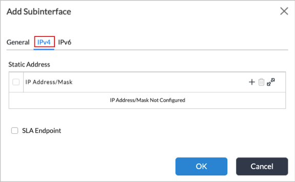
Field Description Static Address Click the Add icon, then enter an IPv4 address and subnet mask for the subinterface.SLA Endpoint Click to make the subinterface an SLA endpoint. When enabled, the subinterface will be used as source address (by appliance on which it is enabled) and destination address (by other SD-WAN appliances) for sending IP-SLA probes for Data-Driven SLA Monitoring. - Click the IPv6 tab, then enter information for the following fields.
- To configure a static IPv6 address, click the IPv6 box, click the Static Address box, then enter information for the following fields.

Field Description Static Address Click to add a static IPv6 address, then click the Add icon and enter an IPv6 address and subnet mask. DHCPv6 (Group of Fields) Click to add a DHCPv6 address. - Client IA Type (Group of Fields)
- IA NA
Click to assign a global Identity Association Nontemporary Address on a WAN link. - IA PD
IA for Prefix Designation to request a block of IPv6 addresses from a DHCP server.
Click to assign
refers to the DHCP Unique Identifier (DUID) to obtain IP addresses and configuration information from a DHCPv6 server. The DUID, along with an Identity Association Identifier (IAID) for a specific interface, forms the client ID
- Delegated Prefix Pool
(For IA PD only.) Enter the name of the delegated prefix pool. - EUI 64
Click to automatically generate a unique 64-bit Interface ID for an IPv6 address. IPv6 Interface Mode Select the IPv6 interface mode:
- Host—This is the default. Use to configure stateful DHCPv6.
- Router—Select to configure stateless automatic address configuration (SLAAC). You must also configure a router advertisement that corresponds to the IPv6 address and prefix length. For more information, see Configure Virtual Routers
Interface Identifier If you configure the subinterface using a static IPv6 address, enter the interface identifier, which is a valid IPv6 address. SLA Endpoint Click to make the IPv6 subinterface an SLA endpoint. When enabled, the subinterface will be used as source address (by appliance on which it is enabled) and destination address (by other SD-WAN appliances) for sending IP-SLA probes for Data-Driven SLA Monitoring. - Click OK.
- To configure a static IPv6 address, click the IPv6 box, click the Static Address box, then enter information for the following fields.
- In the Add DSL Interface screen, select the PPPoE tab to configure a mapping, and enter information for the following fields.

Fields Description Preferred IP Enter the preferred source IP address for the tunnel. Service Name Enter the service name. Access Concentrator Enter the name of the access concentrator. The access concentrator name on both the client and the server must be the same to establish the PPPoE session. Username Enter the username. Password Enter the password. LCP Echo Interval Enter how often to send LCP echo requests to peer, in seconds.
Range: 1 through 255 secondsDefault: 5 seconds
LCP Echo Failure Enter the number of LCP echo requests to send without receiving a valid LCP echo reply before assuming that the peer is unreachable (dead).
Range: 1 through 255Default: 3
Route Preference Enter the route preference to use when installing the default route.
Range: 1 through 255 - Click OK.
- Select the DSL tab, and enter information for the following fields.

Fields Description Multiplexing Type (Required) Select the multiplexing type:
- LLC (Default)
- VC-MUX
VLAN Tag (Required) Enter the VLAN ID configured for the DSL line. VCI (Required) Enter the virtual channel identifier.
Range: 32 through 65535; 0 through 31 are reserved
Default: 55
VPI (Required) Enter the virtual path identifier.
Range: 0 through 256
Default: 65
- Click OK.
Configure WiFi Interfaces
For information about configuring WiFi interfaces, see Configure WiFi.
Configure WWAN Interfaces
For information about configuring WWAN interfaces for LTE, 4G, or 5G service, see Configure WWAN.
Configure uCPE Interfaces
To configure a uCPE interface:
- In Director view:
- Select the Administration tab in the top menu bar.
- Select Appliances in the left menu bar.
- Select a device name in the main panel. The view changes to Appliance view.
- Select the Configuration tab in the top menu bar.
- Select Networking > Interfaces in the left menu bar.
- Select the uCPE tab in the horizontal menu bar.

- Click the Add icon. In the Add uCPE Interface popup window, enter information for the following fields.

Field Description Interface Select the interface on which to configure uCPE. Disable Click to disable the uCPE configuration on the interface. Description Enter a text description of the interfaces. Tags Enter a keyword or phrase that allows you to filter the uCPE interface. This is useful when you have many profiles and want to view those that are tagged with a particular keyword. MTU Enter a value for the maximum transmission unit (MTU), which is the size, in bytes, of the largest protocol data packet that the port can receive or transmit.
Range: 72 through 9000 bytes
Default: None
Virtual Wire Click to enable virtual wire on the interface. Promiscuous Click to enable promiscuous mode on the interface so that the interface forwards all traffic it receives. Mirror Interface Click to create a copy of the interface. DHCP Trusted Click to enable the ports to be DHCP trusted ports. You can designate a port as trusted for DHCP if it connects to a legitimate DHCP server. This allows the port to send DHCP requests and acknowledgements. Bandwidth (Group of Fields) Allows you to specify the bandwidth available on a link to upload and download data. This information is used in computing adaptive traffic shaping. - Autoconfiguration
Click to disable autoconfiguration. Then, enter the URI for the uCPE interface. - URI
If you disable autoconfiguration, enter the Uniform Resource Identifier (URI) for the uCPE interface. - Uplink (Kbps)
Enter the bandwidth available on the link for uploading data, in kilobits per second (Kbps).
Range: 1 through 10000000 Kbps
Default: None
- Downlink (Kbps)
Enter the bandwidth available on the link for downloading data, in kilobits per second (Kbps).
Range: 1 through 10000000 Kbps
Default: None
- Click the Add icon to add a subinterface. In the Add Subinterface popup window, enter information for the following fields.

Field Description Unit (Required) Enter a unit number for the subinterface. VLAN ID
Enter the virtual LAN ID for the subinterface.
Range: 0 through 4094
Description Enter a text description for the subinterface. It can be a text string up to 255 characters. MTU
Enter the size, in bytes, of the largest protocol data unit that the subinterface can receive or transmit.
Range: 72 through 9000 bytes
Default: None
Interface Mode Select the interface mode:
- Normal
- NSH Reflect
- Redundancy
Bandwidth (Group of Fields) Allows you to specify the bandwidth available on a link to upload and download data. This information is used in computing adaptive traffic shaping. - Uplink (Kbps)
Enter the bandwidth available on the link for uploading data, in kilobits per second (Kbps).
Range: 1 through 10000000 Kbps
Default: None
- Downlink (Kbps)
Enter the bandwidth available on the link for downloading data, in kilobits per second (Kbps).
Range: 1 through 10000000 Kbps
Default: None
- Select the IPv4 tab, then enter information for the following fields.

Field Description FQDN Enter the fully qualified domain name for the IPv4 subinterface. DHCP v4 Click to use DHCP to assign an IPv4 address for the subinterface. Disable Click to not activate the subinterface after you configure it. IPv6 Interface Mode Select the IPv6 interface mode:
- Host—Use to configure stateful DHCPv6. This is the default.
- Router—Select to configure stateless automatic address configuration (SLAAC). You must also configure a router advertisement that corresponds to the IPv6 address and prefix length. For more information, see Configure Virtual Routers.
Interface Identifier If you configure the subinterface using a static IPv6 address, enter the interface identifier, which is a valid IPv6 address. Static Address
Use a static IPv4 or IPv6 address for the subinterface. Click the Add icon and enter the IPv4 or IPv6 address and subnet mask.Delegated Prefix Pool Enter the name and IPv6 address of the delegated prefix pool, then click the Add icon to add the delegated prefix pool.DHCPv6
Click to use DHCP to assign an IPv6 address for the subinterface. - Client IA Type
Select the client identity association type:
- IA-NA
- IA-PD
- Delegated Prefix Pool
If you selected IA-PD as the client IA type, enter the name and IP address of the delegated prefix pool. Static ARP (Tab)
Select to configure static ARP mapping. - Subnet Address/Mask
Select the subnet address and mask. - Host IP Address
Enter the IP address of the host. - MAC Address
Enter the MAC address of the host. - Add icon
Click to add the static ARP mapping. - Click OK.
Configure Loopback Interfaces
You configure loopback interfaces in routing instances that route large amounts of data traffic and that require continuous connectivity. Loopback interfaces are always up. Loopback interfaces are primarily used for OSPF and BGP, because connectivity is never down. A routing instance or domain can have only one loopback interface.
A loopback interface does not need to have a standard IP address. However, its mask is always /32, and you cannot change this value.
For a service provider with two routers, each router has a loopback interface and the routers maintain data connectivity over the loopback interface.
To configure a loopback interface:
- In Director view:
- Select the Administration tab in the top menu bar.
- Select Appliances in the left menu bar.
- Select a device name in the main panel. The view changes to Appliance view.
- Select the Configuration tab in the top menu bar.
- Select Networking > Interfaces in the left menu bar.
- Select the Loopback tab in the horizontal menu bar.

- Click the Add icon. In the Add Loopback Interface popup window, enter information for the following fields.

Field Description Interface (Required) Enter the slot number for the loopback interface. Loopback interface names start with lo. Description Enter a text description for the interface. It can be a text string up to 255 characters. - Click the Add icon to add a subinterface. In the Add Subinterface popup window, enter information for the following fields.

Field Description Unit (Required) Enter a unit number for the subinterface. Description Enter a text description for the subinterface. It can be a text string up to 255 characters. IP Addresses Click the
Add icon and enter an IP address for the subinterface. You can enter multiple IP addresses.Bandwidth (Group of Fields) Allows you to specify the bandwidth available on a link to upload and download data. This information is used in computing adaptive traffic shaping. - Uplink (Kbps)
Enter the bandwidth available on the link for uploading data, in kilobits per second (Kbps).
Range: 1 through 10000000 Kbps
Default: None
- Downlink (Kbps)
Enter the bandwidth available on the link for downloading data, in kilobits per second (Kbps).
Range: 1 through 10000000 Kbps
Default: None
IPv4 SLA Endpoint Click to make the IPv4 subinterface an SLA endpoint. When enabled, the subinterface will be used as source address (by appliance on which it is enabled) and destination address (by other SD-WAN appliances) for sending IP-SLA probes for Data-Driven SLA Monitoring. IPv6 SLA Endpoint Click to make the IPv6 subinterface an SLA endpoint. When enabled, the subinterface will be used as source address (by appliance on which it is enabled) and destination address (by other SD-WAN appliances) for sending IP-SLA probes for Data-Driven SLA Monitoring. - Click OK.
Configure Management Interfaces
A management interface is an out-of-band network that enables you to log in to a VOS device using SSH. You can also use a management interface for SNMP operations.
To configure a management interface:
- In Director view:
- Select the Administration tab in the top menu bar.
- Select Appliances in the left menu bar.
- Select a device name in the main panel. The view changes to Appliance view.
- Select the Configuration tab in the top menu bar.
- Select Networking > Interfaces in the left menu bar.
- Select the Management tab.
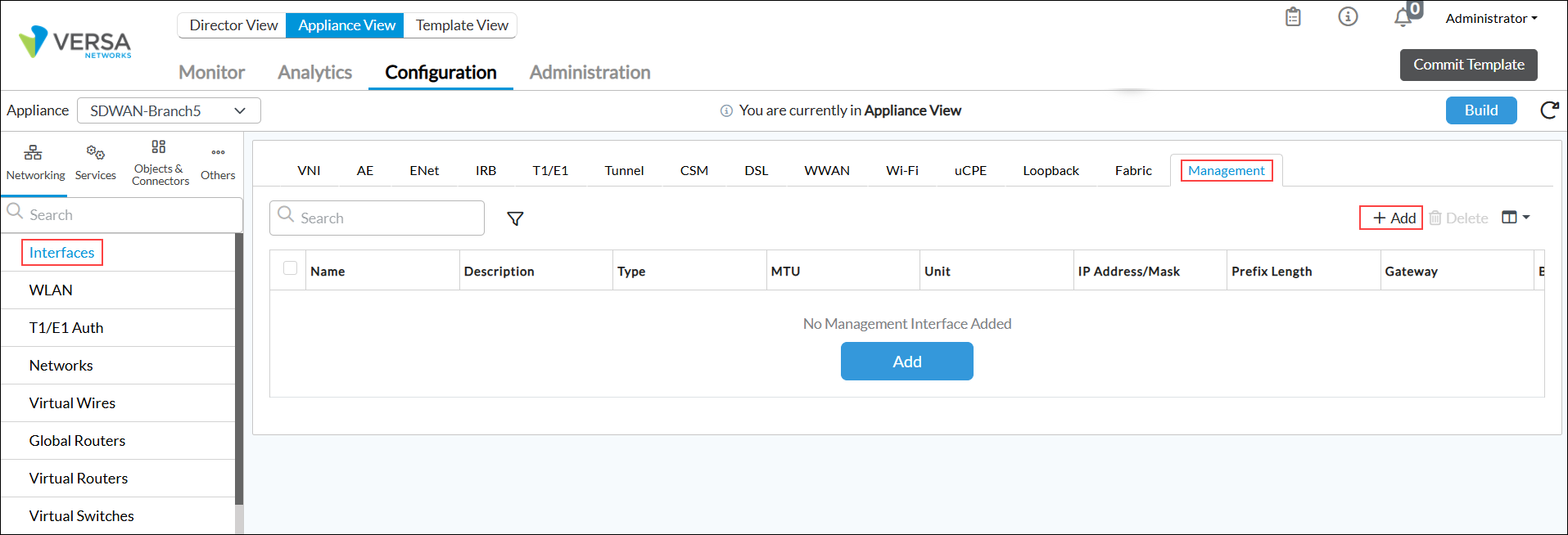
- Click the Add icon. In the Add Management Interface popup window, enter information for the following fields.

Field Description Interface (Required) Enter the port and slot numbers for the management interface. Management interfaces are Ethernet interfaces, and their names start with eth. The port number must be 0, and the slot number must be 0. Disable Select to disable the interface after you configure it. Type Select the interface type:
- External
- Internal
MTU Enter the maximum transmission unit size, in bytes, of largest protocol data unit that the port can receive or transmit.
Range: 72 through 9000 bytesSpeed Select the data transfer speed, in megabits per second (Mbps):
- 10
- 100
- 1000
Duplex Select how to negotiate between the device interface and switch interface:
- Full—Transmit data in both directions on a signal carrier at the same time.
- Half
MAC Address Enter the MAC address of the interface. Description Enter a text description for the interface. It can be a string up to 255 characters.
- Click the Add icon in the Subinterfaces table to add a subinterface. In the Add Subinterface popup window, enter information for the following fields.
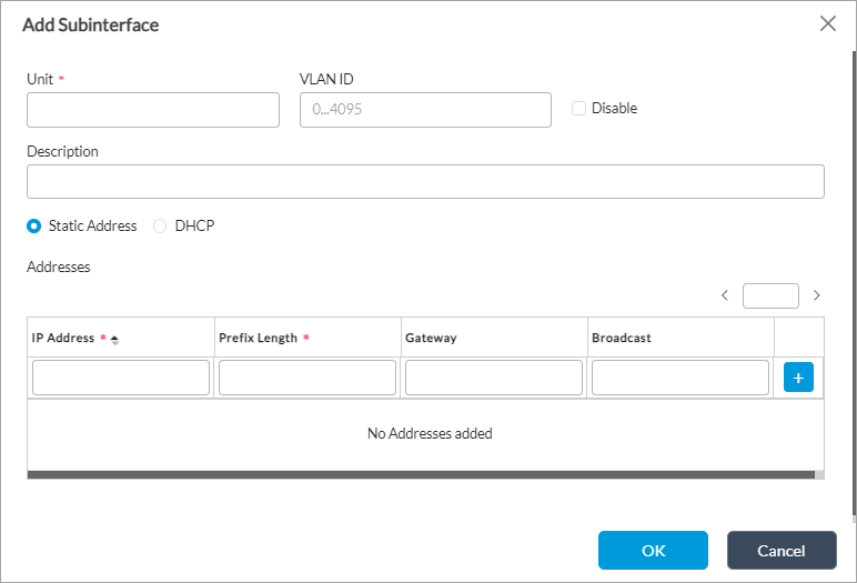
Field Description Unit (Required) Enter the subinterface number. VLAN ID Enter virtual LAN ID of the subinterface. You cannot configure VLAN IDs for subinterfaces based on the eth-0/0 interface, so do not configure any value in the VLAN ID field. Disable Click to not activate the subinterface after it is configured. Description Enter a text description for the subinterface. It can be a text string up to 255 characters. Static Address Click and select the IP address for the subinterface. Click the Add icon to add a static address.DHCP Click to use DHCP to assign an IP address for the subinterface. Address (Table) Enter IP addresses for the subinterface. - IP Address (Required)
Enter the IP address for the subinterface. - Prefix Length (Required)
Enter the prefix length for the IP address. - Gateway
Enter the IP address of the gateway. - Broadcast
Enter the broadcast address for the subinterface.
- Click OK.
Configure a Management Port To Be a Data Port
For Releases 21.1.3, 21.2.1, and later.
On some Versa CSG series appliances, you can reconfigure a management port so that it can be used as a data port. Doing this is useful if you are running out of physical ports on a VOS device and want to repurpose a management port so that it can be used to send data traffic.
The eth0 port on CSG series appliances, which is labeled on the chassis with a wrench tool symbol, is an out-of-band management port. By default, this port is configured as a host-exclusive port, which means it can be used only by the host OS.
The table below shows the Versa Networks and third-party appliances on which you can configure the ports to be data-exclusive ports so that they can carry data traffic.
| Appliance | Interface | Port |
|---|---|---|
| Versa CSG150 | vni-0/3 | Port 3 |
| Versa CSG350 | vni-0/3 | Port 3 |
| Versa CSG355 | vni-0/5 | Port 5 |
| Versa CSG365 | vni-0/5 | Port 5 |
| Versa CSG620 | vni-0/3 | Port 3 |
| Versa CSG730 | vni-0/5 | Port 5 |
| Versa CSG750 | vni-0/5 | Port 5 |
| Versa CSG770 | vni-0/5 | Port 5 |
| Versa CSG780 | vni-0/5 | Port 5 |
| V110-ECO | vni-0/3 | Port 3 |
| Versa SteelConnect EX-385 (Rebranded CSG730) |
vni-0/3 | Port 3 |
| Versa SteelConnect EX-485 (Rebranded CSG750) |
vni-0/5 | Port 5 |
| Versa SteelConnect EX-685 (Rebranded CSG770) |
vni-0/5 | Port 5 |
| Dell VEP1425 | vni-0/7 | Port 7 |
| Dell VEP1445 | vni-0/7 | Port 7 |
| Dell VEP1485 | vni-0/7 | Port 7 |
| Dell VEP1420 | vni-0/3 | Port 3 |
| Dell XR5610-V950 | vni-0/3 | Port 3 |
| Lanner LEC-6041 | vni-0/6 | Port 6 |
| Advantech FWA-1112VC | vni-0/3 | Port 3 |
| Nexcom DTA1152BC4 | vni-0/3 | Port 3 |
To configure a management port to be a data port:
- In Director view:
- Select the Configuration tab in the top menu bar.
- Select Devices > Devices in the horizontal menu bar.
- Select an organization in the left menu bar.
- Select a device in the main pane. The view changes to Appliance view.
- Select the Configuration tab in the top menu bar.
- Select Others > System > Configuration > Configuration in the left menu bar.
- In the main pane, locate the Platform panel.

- Click the
 Edit icon. In the Edit Platform popup window, select the Management Port tab and enter information for the following fields.

Field Description - Usage Model
Select the usage model for the platform's management port:
- Data Exclusive—Use the management port exclusively for Versa services. Selecting this option moves the eth0 port to be a part of the VOS vni interface and so allows the management port to transmit VOS data traffic.
- Host Exclusive—Use the management port exclusively for the host OS. Selecting this option keeps the eth0 interface as part of the Linux name space. This is the default.
- Shared—Share the management port between Versa services and the host OS. Note that it is recommended that you not use this option in production environments.
- Click the NPU tab, then enter information for the following fields.
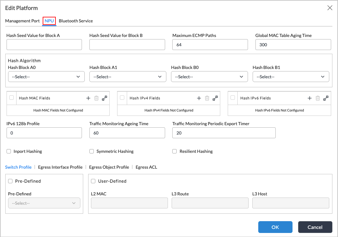
Field Description Hash Seed Value for Block A Enter the hash seed value for block A, in bytes.
Range: 1 through 4294967295 bytes
Default: 4 bytes
Hash Seed Value for Block B Enter the hash seed value for block B, in bytes.
Range: 1 through 4294967295 bytes
Default: 1011 bytes
Maximum ECMP Paths Enter the maximum number of equal-cost multipath (ECMP) paths.
Range: 2 through 128 paths
Default: None
Global MAC Table Aging Time Enter the systemwide MAC table aging timer for the NPU platform.
Range: 10 through 3600 seconds
Default: 300 seconds
Hash Algorithm (Group of Fields) - Hash Block A0
Select the hash block A0 value to use for the hash algorithm.
Default: Koopman CRC32 16-LSBs
- Hash Block A1
Select the hash block A1 value to use for the hash algorithm.
Default: Koopman CRC32 16-MSBs
- Hash Block B0
Select the hash block B0 value to use for the hash algorithm.
Default: Ethernet CRC32 16-LSBs
- Hash Block B1
Select the hash block B1 value to use for the hash algorithm.
Default: Ethernet CRC32 16-MSBs
Hash MAC Fields Click the
Add icon, and then select the Layer 2 hash MAC fields:
- Destination MAC (dst-mac)
- Ethernet type (ethertype)
- Source MAC (src-mac)
- VLAN
Hash IPv4 Fields Click the
- Destination IP (dst-ip)
- IP protocol
- Layer 4 destination port (l4dstport)
- Layer 4 source port (l4srcport)
- Source IP (src-ip)
- VLAN
Hash IPv6 Fields Click the
- Destination IP (dst-ipv6)
- Flow label
- IP protocol
- Layer 4 source port (l4srcport)
- Layer 4 destination port (l4dstport)
- Source IP (src-ipv6)
- VLAN
In-Port Hashing Click to enable inclusion of the incoming port for hashing. By default, in-port hashing is disabled. Symmetric Hashing Click to enable symmetric hashing. By default, symmetric hashing is disabled. Resilient Hashing Click to enable resilient hashing. By default, resilient hashing is disabled. - In the Switch Profile subtab, enter information for the following fields.
Field Description Predefined Click, and then select a predefined egress interface.
- Balanced—This is the default.
- Overlay
- Underlay
User-Defined (Group of Fields) Click to configure a user-defined egress interface allocation, and then enter the sizes of overlay and underlay egress interfaces, as percentages. The two values must add up to 100 percent.
- Underlay (Required)
Enter a value for the number of underlay entries, as a percentage.
- Overlay (Required)
Enter a value for the number of overlay entries, as a percentage.
- Click the Egress Interface Profile subtab, then enter information for the following fields.

Field Description Predefined Click, and then select a predefined profile. These profiles allocate predefined UFT CAM shared banks that are available on the NPU switch to any of the following route tables:
- scaled-L2-mac—Layer 2 MAC route table.
- scaled-L3-host—Layer 3 host entries.
- scaled-L3-routes—Layer 3 route table.
- scaled-ztna-default—Default route table used for ZTNA.
- scaled-ztna-routes—Route table used ZTNA.
User-Defined (Group of Fields) Click to configure a user-defined switching profile, and then enter values to allocate the shared banks for Layer 2 MAC, Layer 3 host, and Layer 3 route tables for the user-defined profile as percentages of the bank size. The three values must add up to 100 percent.
- Layer 2 MAC (Required)
Enter a value for the Layer 2 MAC entries, as a percentage.
- Layer 3 Route (Required)
Enter a value for the number of Layer 3 routes, as a percentage.
- Click the Egress Interface Object subtab, then enter information for the following fields.

Field Description Predefined Click, and then select a predefined egress object between the overlay and underlay networks:
- Balanced
- Overlay
- Underlay—This is the default.
User Defined (Group of Fields) Click to configure a custom allocation of egress objects, and then enter the sizes of overlay and underlay egress objects. The two values must add up to 100 percent.
- Underlay (Required)
Enter a value for the number of egress objects to be allocated for underlay entries, as a percentage.
- Overlay (Required)
Enter a value for the number of egress objects to be allocated for overlay entries, as a percentage.
- Click the Egress Interface Object subtab, then enter information for the following fields.

Field Description Layer 2 ACL (Group of Fields) Select Match criteria for Layer 2 ACLs. - Match To Host
Select Enabled or Disabled. - Match From Host
Select Enabled or Disabled. - Match Mirror
Select Enabled or Disabled. IPv4 ACL (Group of Fields) Select Match criteria for IPv4 ACLs. - Match To Host
Select Enabled or Disabled. - Match From Host
Select Enabled or Disabled. - Match Mirror
Select Enabled or Disabled. IPv6 ACL (Group of Fields) Select Match criteria for IPv6 ACLs. - Match To Host
Select Enabled or Disabled. - Match From Host
Select Enabled or Disabled. - Match Mirror
Select Enabled or Disabled.
- In the Edit Platform screen, select the Bluetooth Service tab, then click the Bluetooth Service checkbox to enable Bluetooth on the platform.

- Click OK
- For the changes to take effect, restart the Versa services manually, either from the shell or the CLI on the appliance.
admin@csg:~$ vsh restart
admin@csg-cli> request system restart
Supported Software Information
Releases 20.2 and later support all content described in this article, except:
- In Releases 20.2.4, 21.1.3, 21.2.1, and later, you can configure a management port to be a data port on some CSG appliances.
- Release 21.1.1 adds support for DSL and T1 Interfaces.
- Release 21.2.1 adds support for proxy ARP, proxy NDP, specifying uplink and downlink bandwidth per subinterface or unit for adaptive shaping, specifying a chassis ID and admin key for aggregated Ethernet interfaces, multilink for T1/E1 interfaces, configuring PAP and CHAP authentication parameters for T1/E1 authentication, and configuring PoE support for Ethernet interfaces.
- Release 22.1.1 adds support for configuration of T1 interface cable length and IPv4 IPIP tunnels; LTE interfaces are renamed to WWAN interfaces.
- Release 22.1.4 adds support for breakout mode to channelize 100-Gigabit Ethernet ports on CSX8000 switches, CSX4000 switches, and CSG3000 series devices, PoE Port Priority, and Smart Auto Speed for link speed.
- Release 22.1.4 (Service Release dated 2024-12-23) adds support for point-to-multi-point GRE and static NHRP mapping.
- Release 23.1.1 adds support for configuring IPv6 interfaces as SLA endpoints for data-driven SLAM monitoring (DDSLAM) IP-SLA packets and CSM interfaces.
- Release 23.1.2 adds workflows for configuring aggregated Ethernet Layer 2 interfaces and aggregated Ethernet LAN interfaces.