Configure an Application Delivery Controller
![]() For supported software information, click here.
For supported software information, click here.
An application delivery controller (ADC) is a component of a Versa Operating SystemTM (VOSTM) device that accepts TCP or UDP connections from a process that initiates a connection. The ADC maps the connection to one of a set of receiving nodes, using a configurable load-balancing algorithm to choose a receiving node in the set. The ADC uses network address translation (NAT) to map the connection between the process and the receiving node.
You can configure an ADC to toggle connections from an initiating process between a default set of receiving nodes (a pool) and a backup pool. The ADC can detect when the default pool is unreachable and, in that case, maps connections to the backup pool instead.
You can use an ADC to do the following:
- Load-balance log export functionality (LEF) connections between VOS devices and the nodes in an Analytics cluster. In this case, you configure the ADC on a Controller node, and LEF on the VOS device initiates the TCP or UDP connection. The ADC maps the connection to one of the nodes in the Analytics cluster. For information about LEF connections and the ADC, see VOS Devices and Log Export Functionality in Versa Analytics Configuration Concepts.
- Toggle LEF connections from VOS devices between a primary and a backup Analytics cluster. In this case, you configure the ADC on a Controller node, and LEF on the VOS device initiates the TCP or UDP connection. The ADC maps the connection to one of the nodes in the primary cluster. If the primary cluster is unreachable, the ADC maps the connection to one of the nodes in the backup cluster instead.
- Load-balance connections between remote systems and web servers. In this case, you configure the ADC on a branch VOS device, and a process, such as a browser, on the remote system initiates the TCP or UDP connection. The ADC maps the connection to one of a set of web servers. As additional processes initiate connections, the ADC distributes them among the set of web servers.
To configure an ADC, you create an ADC service. This service defines a virtual IP address and TCP or UDP port number combination, called an ADC service tuple, that the service uses to listen for incoming connections. For each receiving node, you configure an ADC server that specifies the IP address and TCP or UDP port number that the receiving node uses to listen for incoming connections. You then place the ADC servers into an ADC server pool. You associate the ADC service with an ADC server pool. You can optionally configure a backup ADC server pool.
To configure an ADC service, you do the following:
- Configure one or more ADC servers.
- Configure a pool of ADC servers.
- Configure the ADC service itself, which associates an ADC service tuple with the pool of ADC servers.
When a process initiates a TCP or UDP connection to the ADC service tuple, the ADC service receives these connections and distributes them to the members of the ADC server pool. If you have configured a backup pool, the ADC service toggles the connections to the backup pool when the default pool is unreachable. You can configure the ADC service to return to the default pool when it becomes reachable again.
Note: When configuring an ADC service to distribute LEF connections to Analytics clusters, select the provider organization when configuring ADC servers, server pools, services, and server monitors. You can use the ADC service from any of the tenant organizations for the provider.
You can also configure ADC monitors to probe the health state of an ADC server.
ADC Monitors for Analytics Nodes
ADC monitors of type TCP determine the health state of a node by forming TCP connections to the destination of an ADC server. By default, these TCP connections use the same port as the ADC server destination, thus increasing the number of connections to the port. If the ADC server is for a local collector on an Analytics node, the added connections from the monitor may cause the local collector to exceed its connection limit. To avoid this issue, you can configure a dummy local collector that uses the same IP address as the primary local collector but uses an alternate port number on the Analytics node, Then, for the ADC service you configure an ADC monitor to use the dummy's port number, referred to as an alias service port.
In the following illustration, an ADC service is configured with two ADC servers, one for each of two log collector nodes in an Analytics cluster. ADC Server 1 facilitates TCP connections to a local collector at IP address 192.45.31.1, port 1234. ADC Monitor 1 is associated with ADC Server 1, and is configured to use alias service port number 1235. A similar configuration is used for Log Collector node 2.

Enable an ADC
Before you configure ADC services, you must enable an ADC on the VOS device. To do this, you enable the ADC globally in the service node group used by the VOS device. Then you can enable the ADC for individual organizations, which you do by adding ADC services to the organization limits for the provider or tenant organization.
For information about configuring service node groups, see Configure Service Node Groups. For information about configuring organization limits, see Configure Organization Limits.
To enable the ADC globally for a VOS device:
- In Director view:
- Select the Administration tab in the top menu bar.
- Select Appliances in the left menu bar.
- In the main pane, click the name of the VOS device. The view changes to Appliance view.
- Select the Configuration tab in the top menu bar.
- Select Others > Service Nodes > Service Node Groups in the left menu bar. The main pane displays the service node groups that are already configured.

- Click the name of the service node group. The Edit Service Node Group popup window displays.

- In the Selected Services table, ensure that ADC is listed. If it is not listed, click ADC in the Available Services table to move it to the Selected Services table.
- Click OK
- Refresh the browser window.
To enable the ADC for an organization on a VOS device:
- In Director view:
- Select the Administration tab in the top menu bar.
- Select Appliances in the left menu bar.
- In the main pane, click the name of the VOS device. The view changes to Appliance view.
- Select the Configuration tab in the top menu bar.
- Select Others > Organization > Limits in the left menu bar. The main pane displays the organizations that are already configured.

- Click the name of the organization. The Edit Organization Limit popup window displays.
- Select the Services tab.

- In the Services table, click the
 Add icon and select ADC.
 - Click OK.
- Refresh the browser window.
Configure ADC Servers
An ADC server specifies the IP address, port, and protocol of a receiving node. The ADC uses the ADC server information to determine the receiving node on which to map an incoming TCP or UDP connection. For the ADC server, you can configure a monitor that the ADC uses to determine the reachability of the receiving node.
To configure an ADC server:
- In Director view:
- Select the Administration tab in the top menu bar.
- Select Appliances in the left menu bar.
- Select the VOS device on which you want to configure the ADC server in the main pane. The view changes to Appliance view.
- Select the Configuration tab in the top menu bar.
- Select Services in the left menu bar.
- Select the organization in the Organization field in the horizontal menu bar.
- Select ADC > Local Load Balancer > Server in the left menu bar. The main pane displays the ADC servers that are already configured.

- Click the
 Add icon to define an ADC server, or click the name of an existing server to edit it. In the Add/Edit Server popup window, enter information for the following fields.

Field Description Name (Required) Enter a name for the ADC server. Description Enter a text description for the server. Tags Enter a text string or phrase to associate with the server name. Tags allow you to locate a name when you perform a filtered search of all names. Type (Required) Select the protocol to use for the connection between the ADC and the receiving node:
- Any
- TCP
- UDP
Disable Server Select to disable the server configuration after you configure it. IP Address (Required) Enter the IP address of the receiving node. For Analytics log collector nodes, this is normally the southbound IP address of the Analytics node. Port (Required) Enter the port number on which the receiving node listens for connections. Routing Instance Select the routing instance to use to reach the ADC server. Availability Requirement Enter the availability requirement. Currently, this field is not supported. Monitors (Table) Select one or more monitors to attach to the ADC server. If you do not attach a monitor, the ICMP monitor is attached by default. For more information, see Configure an ADC Server Monitor, below. - Available
Select a monitor. Click Add All to select all monitors. - Selected
Displays the selected monitors. Click X to remove an individual monitor, or click Remove All to remove all monitors. - Click OK.
Configure ADC Server Pools
An ADC server pool consists of a list of ADC servers, called members. You use ADC server pools when you configure an ADC service, as described in Configure an ADC Service, below. If the pool contains more than one member, incoming connections accepted by the ADC service are mapped to the members using the configured load-balancing algorithm. If a member becomes inoperative, the ADC service automatically redirects any currently mapped connections to operating members of the pool. The ADC service monitors attached to the members determine their operational status.
When using a weighted algorithm, such as weighted round-robin, you assign an integer value, called the ratio, to each pool member. The ADC service uses the ratio to determine the number of connections to map to each member. For example, if an ADC server pool contains the following members:
- Server 1, with ratio 1
- Server 2, with ratio 4
- Server 3, with ratio 3
Then, an ADC service using the pool maps each set of 8 connections as follows:
- One connection is mapped to Server 1
- Four connections are mapped to Server 2
- Three connections are mapped to Server 3
To configure an ADC server pool:
- In Director view:
- Select the Administration tab in the top menu bar.
- Select Appliances in the left menu bar.
- Select the VOS device on which you want to configure the ADC server pool in the main pane. The view changes to Appliance view.
- Select the Configuration tab in the top menu bar.
- Select Services in the left menu bar.
- Select the organization in the Organization field in the horizontal menu bar.
- Select ADC > Local Load Balancer > Server Pools in the left menu bar.
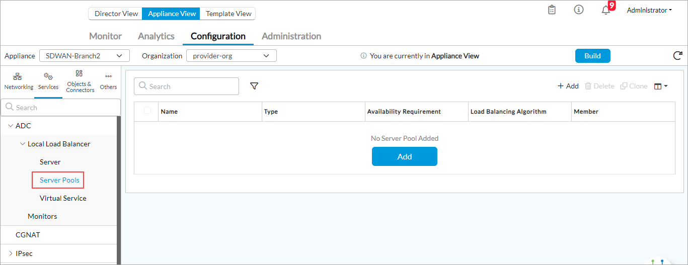
- Click the
 Add icon to add a server pool, or click the name of an existing server pool to edit it. In the Add/Edit Server Pool popup window, enter information for the following fields.

Field Description Name (Required) Enter a name for the server pool. Description Enter a text description for the server pool. Tags Enter a text string or phrase to associate with the server pool name. Tags allow you to locate a name when you perform a filtered search of all names. Availability Requirement (For Releases 22.1.1 and later.) Enter the minimum number of available ADC servers required for the server pool to be marked as Up. ADC server availability is determined by its attached ADC monitor. Type (Required) Select the protocol to use for the connection:
- Any
- TCP
- UDP
Load-Balancing Algorithm Select an algorithm to use to distribute the connections:
- Destination IP hash
- IP hash
- Least connections
- Least response time
- Round robin
- Source IP hash
- Weighted least connections
- Weighted least response time
- Weighted round-robin
Default: Round robin
Availability Requirement Enter the availability requirement. Member (Table) Select the servers to include in the ADC server pool. - Name (Required)
Select the ADC server. - Pricing
Enter the pricing value for the pool member. - Ratio
Enter the ratio for the server as an integer value.
Range: 1 through 999
Default: 1
- Disable
Click to disable the ADC server after you configure it.  Add icon
Click the  Add icon to add the ADC server to the pool.
 - Click OK.
Configure an ADC Service
To configure an ADC service, you define an ADC service tuple on which to listen for TCP or UDP connections. You can also choose a default pool and a backup pool for the ADC service to use. The ADC service distributes incoming connections among the members of these pools.
To configure an ADC service:
- In Director view:
- Select the Administration tab in the top menu bar.
- Select Appliances in the left menu bar.
- Select the VOS device on which you want to configure the ADC in the main pane. The view changes to Appliance view.
- Select the Configuration tab in the top menu bar.
- Select Services in the left menu bar.
- Select the organization in the Organization field in the horizontal menu bar.
- Select ADC > Local Load Balancer > Virtual Service in the left menu bar.

- Click the
 Add icon to add an ADC service, or click the name of an existing service to edit it. The Edit/Add Virtual Service popup window displays.
 - Select the General tab, and enter information for the following fields.
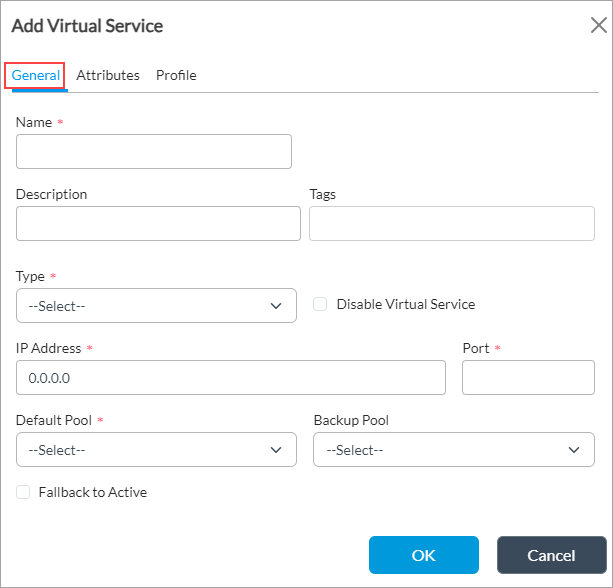
Field Description Name (Required) Enter a name for the ADC service. Description Enter a description of the ADC service. Tags Enter a text string or phrase to associate with the ADC service. Tags allow you to locate a service when you perform a filtered search of all services. Type (Required) Select the protocol for the ADC service:
- Any
- TCP
- UDP
Disable Virtual Service Click to disable the service after you configure it. IP Address (Required) Enter the IP address of the ADC service.
Port (Required) Enter the port number used for the ADC service. Default Pool (Required) Select the default server pool to which to distribute new connections. Backup Pool Select the backup server pool to which to distribute new connections when the default pool is unavailable. Fallback to Active Click so that when the default pool comes back up, all the connections from the backup pool gradually switch back to the default pool. - Select the Attributes tab, and enter information for the following fields.
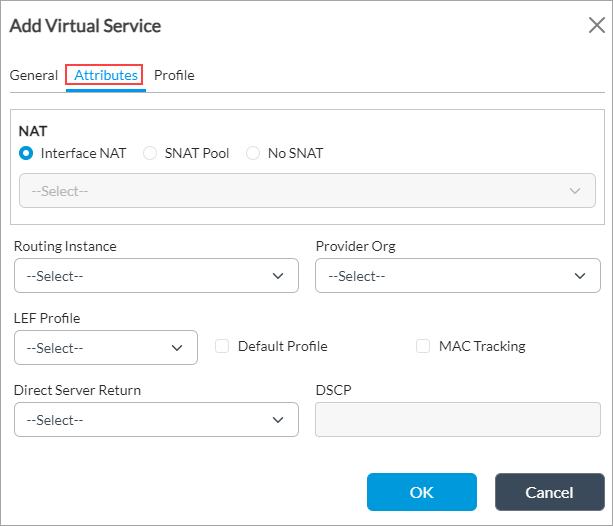
Field Description NAT (Group of Fields) Select the NAT to use when packets traverse to the receiving node. - Interface NAT
Click to use interface NAT. This is the default. - SNAT Pool
Click, and select the SNAT pool to use. - No SNAT
Click to perform no source NATing. Routing Instance Select the routing instance to which the ADC service belongs. Provider Organization Select the provider organization to which the ADC service belongs. LEF Profile Select the LEF profile to use for the ADC service. ADC logs are sent to the active collector of the LEF profile. Default Profile Click to use the default LEF profile instead of selecting a LEF profile. For more information, see Configure a LEF Profile in Configure Log Export Functionality. MAC Tracking Click to track the MAC address. Direct Server Return Click to permit the server (pool member) to respond directly to the client (initiating process). By default, the connection between the initiating process and the pool member uses the ADC as an intermediary in both directions. Configure direct server return to allow the pool member to respond directly to the client that initiated the connection. DSCP Enter the DSCP value.
Configure an ADC Server Monitor
You can configure a monitor to probe the status of an ADC server. The ADC server monitor can use one of the following types of probes:
- ICMP—Probe determines if an ADC server responds to ICMP packets, but cannot determine if a specific TCP port is operational.
- TCP—Probe determines if an ADC server responds to packets for a specific TCP port number, called an alias service port number . By default, the monitor uses the IP address and port number of the ADC server to send the probe.
To configure an ADC server monitor:
- In Director view, select the Administration tab in the top menu bar.
- Select Appliances in the left menu bar.
- Select the VOS device on which you want to configure the ADC monitor in the main pane. The view changes to Appliance view.
- Select the Configuration tab in the top menu bar.
- Select Services in the left menu bar.
- Select the organization in the Organization field in the horizontal menu bar.
- Select ADC > Monitors in the left menu bar.
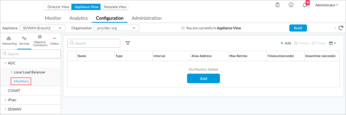
- Click the
 Add icon to add a monitor, or click the name of an existing monitor to edit it. The Add/Edit Monitor popup window displays.
 - Select the General tab, and enter information for the following fields.

Field Description Name (Required) Enter a name for the monitor. Description Enter a text description for the monitor. Tags Enter a text string or phrase to associate with the monitor. Tags allow you to locate a monitor when you perform a filtered search of all monitors.
Types (Required) Select which protocol the monitor uses for its probe:
- ICMP
- TCP
If you select TCP, the Protocol Parameter tab displays.

Select the Protocol Parameter tab, enter a number in the Alias Service Port field, and then click OK.Note: If you configure TCP, and the monitor is associated with an ADC server for a Versa Analytics node, it is recommended that the alias service port number be an alternate port to the one used by the ADC server. In this case, on the Analytics node, you must configure a local collector with the alternate port number to respond to the monitor. Using the alternate port helps to avoid exceeding the port connection limit for the local collector at the ADC server destination port. See ADC Monitors for Analytics Nodes, above.
Alias Address Enter an alternate destination IP address for the monitor.
Interval Enter the frequency at which to send monitor probes.
Range: 0 through 65535 seconds
Default: 5 secondsMaximum Retries Enter the number of times to retry sending a probe before marking a service as down.
Range: 0 through 255
Default: 5Timeout Enter the timeout for monitor probe.
Range: 0 through 65535 seconds
Default: 3 secondsDown Time Enter how long to wait before probing a failed service. This is the minimum time the service is considered down. Configuring a down time duration can help to avoid flapping.
Range: 0 to 65535 seconds
Default: 30 seconds
Monitor an ADC
You can monitor the ADC from the Monitor tab for the VOS device on which the ADC is configured.
To display status and statistics for an ADC:
- In Director view:
- Select the Monitor tab in the top menu bar.
- Select the provider organization in the left menu bar.
- Select the Devices tab in the horizontal menu bar.
- Click the name of the VOS device containing the ADC. The view changes to Appliance view.
- Select the Services tab.
- Select ADC. The following screen displays.

- Select the Load Balancer, Monitor, Server, SSL Proxy, or Virtual Service tab to view status information and statistics about these components of the ADC.
Example: Configure an ADC
This section provides an example of configuring an ADC on a VOS device to distribute TCP connections to a set of internal application servers. The example uses two application servers and assigns load-balancing ratios 1 and 2 to the first and second servers, respectively, so that the ADC maps two connections to the second server for each connection it maps to the first server. For simplicity, the example uses TCP port 22, the port used by SSH, to listen for incoming connections on the ADC and when mapping the connections to the application servers. You can use SSH to log in to the ADC service IP address, here, 192.168.122.231, to test that the ADC service is working. The ADC service maps the SSH login session to one of the two application servers.
The following diagram illustrates the example configuration.

The example uses the following components:
- SDWAN-Branch1—VOS device containing the ADC
- default-sng—Service node group configured with the ADC as an available service
- Tenant1—Organization configured to use the ADC
- Tenant1-LAN-VR—Routing instance that the ADC servers use
- Server1—ADC server name for the first application server, which is assigned a load-balancing ratio of 1
- Server2—ADC server name for the second application server, which is assigned a load-balancing ratio of 2
- Server-Pool-1—ADC server pool containing Server1 and Server2
- Load-Balancer-1—ADC service that maps connections to the servers in Server-Pool-1
- INET-Transport-VR—Routing instance that the ADC service uses to listen for connections
Before configuring ADC service Load-Balancer-1 on device SDWAN-Branch1, you first enable the ADC for service node group default-sng and then you enable the ADC for Tenant1. Then, the ADC item displays within the configuration menus and allows you to configure the ADC service.
To enable the ADC for service group default-sng on VOS device SDWAN-Branch1:
- In Director view, select the Administration tab in the top menu bar.
- Select Appliances in the left menu bar.
- Click SDWAN-Branch1 in the main pane. The view changes to Appliance view.
- Select the Configuration tab in the top menu bar.
- Select Others > Service Nodes > Service Node Groups in the left menu bar.
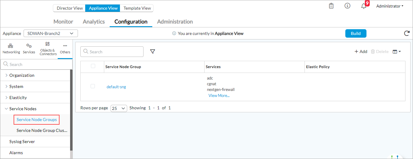
- In the main pane, click default-sng. The Edit Service Node Group popup window displays.
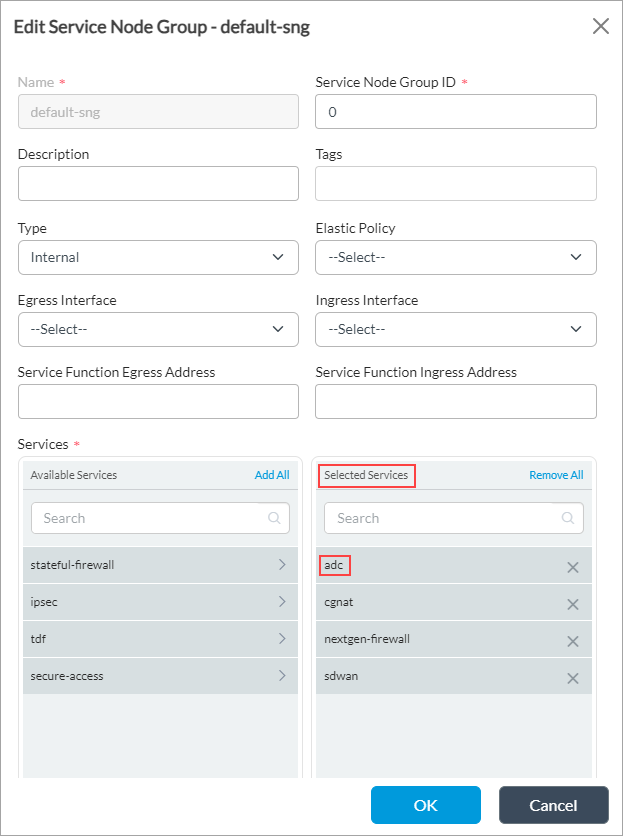
- Ensure that ADC displays in the Selected Services table. If it is not listed, click ADC in the Available Services table to move it to the Selected Services table.
- Click OK.
- Refresh the browser window.
To enable the ADC for organization Tenant1 on VOS device SDWAN-Branch1:
- In Director view:
- Select the Administration tab in the top menu bar.
- Select Appliances in the left menu bar.
- Select SDWAN-Branch1 in the main pane. The view changes to Appliance view.
- Select the Configuration tab in the top menu bar.
- Select Others > Organization > Limits in the left menu bar. The main pane displays the organizations that are already configured.

- In the main pane, click Tenant1. The Edit Organization Limit popup screen displays.
- Select the Services tab.

- In the Services table, click the
 Add icon and then select ADC.
 - Click OK.
- Refresh the browser window.
To configure ADC servers Server1 and Server2:
- Select Services > ADC > Local Load Balancer > Server in the left menu bar.

- Click the
 Add icon. In the Add Server popup window, enter the values listed in the following table.

Field Value Name (Required) Server1 Type (Required) Any IP Address (Required) 10.10.10.101 Port (Required) 22 Routing Instance Tenant1-LAN-VR - Click OK to add Server1.
- Click the
 Add icon again. Enter the values listed in the following table.
Field Value Name Server2 Type Any IP Address 10.10.10.102 Port 22 Routing Instance Tenant1-LAN-VR - Click OK to add Server2.
To configure ADC server pool Server-Pool-1:
- Select Services > ADC > Local Load Balancer > Server Pools in the left menu bar.
- Click the
 Add icon. In the Add Server Pool popup window, enter the values listed in the following table.
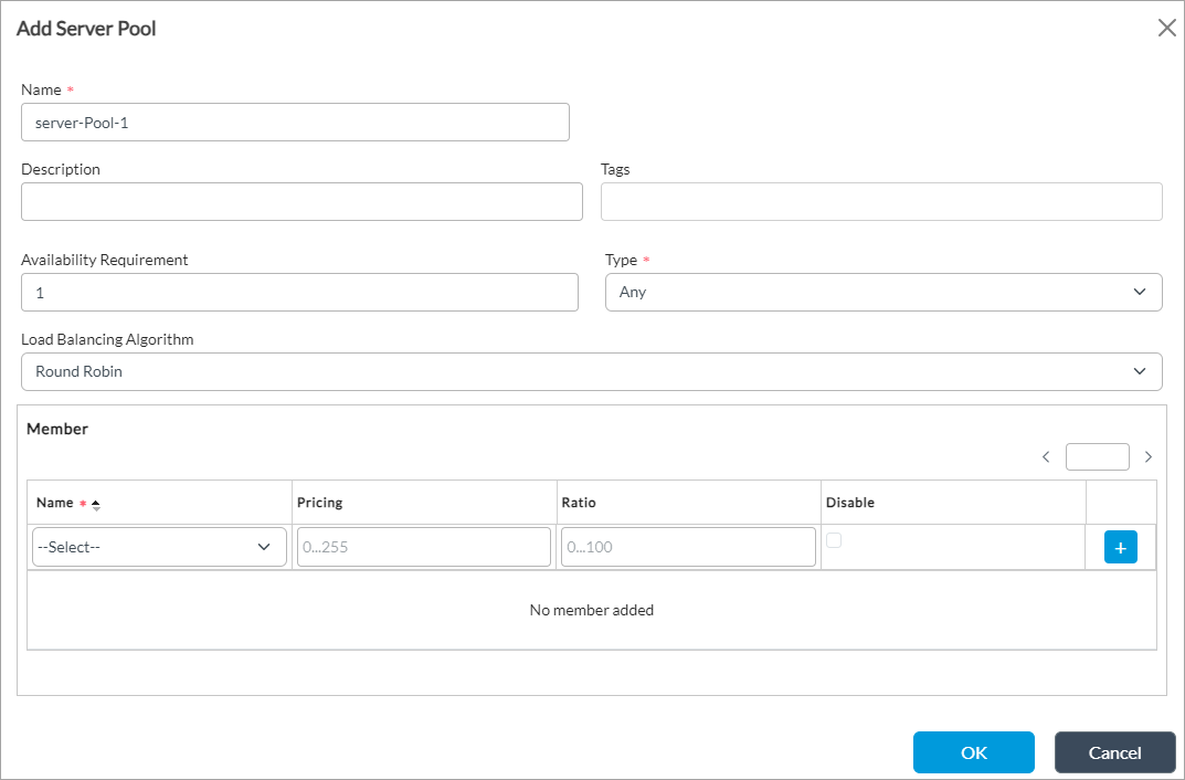
Field Value Name Server-Pool-1 Type Any Load-Balancer Algorithm Weighted Round Robin Member (Group of Fields) - Name
Server1 - Ratio
1  Add icon
Click the  Add icon to add Server1
- Name
Server2 - Ratio
2  Add icon
Click the  Add icon to add Server2
 - Click OK.
To configure the ADC service:
- Select Services > ADC > Local Load Balancer > Virtual Service in the left menu bar.
- Click the
 Add icon to add an ADC service. The Add Virtual Service popup window displays.
 - Select the General tab selected, and enter the values listed in the following table.

Field Value Name Load-Balancer-1 Type Any IP Address 192.168.122.231 Port 22 Default Pool Server-Pool-1 - Select the Attributes tab, and in the Routing Instance field, select INET-Transport-VR.
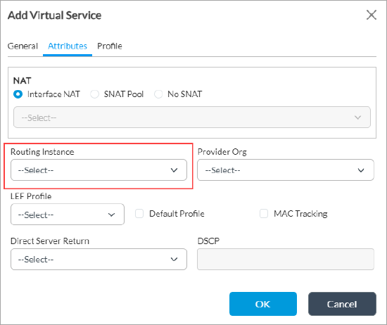
- Click OK.
To verify the example configuration, initiate an SSH session using the ADC service IP address, 192.168.122.231. The ADC service maps the SSH session to either Server1 or Server2.
$ ssh 192.168.122.231
$ hostname
Server1
Supported Software Information
Releases 20.2 and later support all content described in this article, except:
- Release 22.1.1 adds support for availablity requirement for ADC server pools.
