Perform Initial Software Configuration
![]() For supported software information, click here.
For supported software information, click here.
This article describes how to configure the Versa headend components after you have first installed them.
Set Up Director
To set up Director, you typically configure two Director nodes that are redundant and operate in high availability (HA) mode. In HA mode, one Director node operates in active mode and the second operates in backup, or standby, mode. You can also configure a single Director node.
To log in to the Director GUI, it is recommended that you use one of the following browsers:
- Chrome, Version 71 or later
- Firefox, Version 60 or later
Configure Interfaces
- Log in to the shell of one of the Director nodes. Please consult Versa technical support for default credentials. After you log in, the Versa Director setup wizard begins.
- Check the available interfaces. For example:
Administrator@Director01$ sudo ifconfig
sudo: /etc/sudoers.d/10_versa is owned by uid 1002, should be 0
eth0      Link encap:Ethernet  HWaddr 52:54:00:87:f9:71
          inet addr:10.192.94.3  Bcast:10.192.255.255  Mask:255.255.0.0
          inet6 addr: 2001:91::5054:ff:fe87:f971/64 Scope:Global
          inet6 addr: fe80::5054:ff:fe87:f971/64 Scope:Link
          UP BROADCAST RUNNING MULTICAST  MTU:1500  Metric:1
          RX packets:221893549 errors:0 dropped:5135 overruns:0 frame:0
          TX packets:51034108 errors:0 dropped:0 overruns:0 carrier:0
          collisions:0 txqueuelen:1000
          RX bytes:38212605153 (38.2 GB)  TX bytes:7407188416 (7.4 GB)

eth1      Link encap:Ethernet  HWaddr 52:54:00:c5:e3:74
          inet addr:192.168.44.5  Bcast:192.168.44.6  Mask:255.255.255.252
          inet6 addr: fe80::5054:ff:fec5:e374/64 Scope:Link
          UP BROADCAST RUNNING MULTICAST  MTU:1500  Metric:1
          RX packets:3067330 errors:0 dropped:0 overruns:0 frame:0
          TX packets:9111929 errors:0 dropped:0 overruns:0 carrier:0
          collisions:0 txqueuelen:1000
          RX bytes:1132746552 (1.1 GB)  TX bytes:4308138203 (4.3 GB)

lo        Link encap:Local Loopback
          inet addr:127.0.0.1  Mask:255.0.0.0
          inet6 addr: ::1/128 Scope:Host
          UP LOOPBACK RUNNING  MTU:65536  Metric:1
          RX packets:338737540 errors:0 dropped:0 overruns:0 frame:0
          TX packets:338737540 errors:0 dropped:0 overruns:0 carrier:0
          collisions:0 txqueuelen:1
          RX bytes:113421006583 (113.4 GB)  TX bytes:113421006583 (113.4 GB)
- Configure an IP address on the management (northbound) interface, which is eth0, and enable the interface. For example:
Administrator@Director01$ sudo ifconfig eth0 10.192.94.3/16 up
- Configure an IP address on the southbound interface, eth1, and enable the interface. For example:
Administrator@Director01$ sudo ifconfig eth1 192.168.44.5/30 up
- Add the interfaces to the /etc/network/interfaces file to make them persistent. In this file:
- On the "iface eth0" line, change "dynamic" to "static."
- On the "address" line, change the address to the eth0 interface's IP address.
- On the "netmask" line, enter the correct subnetwork mask.
- On the "gateway" line, enter the IP address for the gateway.
- Repeat Steps a, b, and c for the eth1 interface.
For example:
Administrator@Director01$ cat /etc/network/interfaces
# This file describes the network interfaces available on your system
# and how to activate them. For more information, see interfaces(5).

# The loopback network interface
auto lo
iface lo inet loopback

# The primary network interface
auto eth0
iface eth0 inet static
address 10.192.98.102
netmask 255.255.0.0
gateway 10.192.0.1

auto eth1
iface eth1 inet static
address 11.192.98.102
netmask 255.255.255.0
- Initialize the Director node:
Administrator@Director01$ cd /opt/versa/vnms/scripts
Administrator@Director01$ ./vnms-startup.sh
- If configuring a second Director node, repeat Steps 1 through 6 on the second Director node.
The following is an example of running the Director startup script:
Administrator@Director01$ sudo /opt/versa/vnms/scripts/vnms-startup.sh
---------------------------
VERSA DIRECTOR SETUP
---------------------------
Do you want to enter setup? (y/n)? y
----------------------------
Running /opt/versa/vnms/scripts/vnms-startup.sh...
------------------------------
Do you want to setup hostname for system? (y/n)? y
Enter hostname: director-setup-1
Saved 1 file(s)
Added new hostname entry to /etc/hosts
Added new hostname entry to /etc/hostname
Restarting hostname service...
Restarting network service...
Do you want to setup network interface configuration? (y/n)? y
-------------------------------
Setup Network Interfaces
------------------------------
Enter interface name [eg. eth0]: eth0
Existing IP for eth0 is 10.40.30.25
Configuration present for eth0, do you want to re-configure? (y/n)? y
Re-configuring interface eth0
Enter IP Address: 10.40.30.25
Enter Netmask Address: 255.255.0.0
Configure Gateway Address? (y/n)? y
Enter Gateway Address: 10.40.0.1
----------------------------
Adding default route - route add default gw 10.40.0.1
Added interface eth0
Configure another interface? (y/n)? y
Enter interface name [eg. eth0]: eth1
Existing IP for eth1 is 192.168.30.25
Configuration present for eth1, do you want to re-configure? (y/n)? n
Using existing configuration; IP for eth1 is 192.168.30.25
Configure another interface? (y/n)? n
Configure northbound interface (if not configured, default 0.0.0.0 is accepted) (y/n)? y
--------------------------------------
Select Northbound Interface
-------------------------------
Enter interface name [eg. eth0]: eth0
----------------------------
Select Southbound Interface(s)
-----------------------
Enter interface name [eg. eth0]: eth1
Configure another South-Bound interface? (y/n)? n
Restarting network service
Enable secure mode for Director HA ports? (y/n)? y
 => Clearing VNMSHA iptables rules
 => Persist iptable rules and reload..
 => Done.
 => HA is enabled..
 => Peer Director's IP address is: 10.40.30.26
 => Setting up iptables rules
 => Create custom chain "VNMSHA"
 => Allow access to port 22, 4566, 4570, 5432 for 127.0.0.1
 => Allow access to port 22, 4566, 4570, 5432 for 10.40.30.26
 => Allow access to port 22, 4566, 4570, 5432 for 10.40.30.25
 => Disallow access to port 22, 4566, 4570, 5432 for other IPs
 => Persist iptable rules and reload
 => Done
 Secure Director HA communication? (y/n)? y
 Enter PSK: Versa@123
 => Setting up strongSwan ipsec configuration..
 => Restarting ipsec service..
 => Done
 Prompt to set new password at first time UI login? (y/n)? n
 Restarting versa director services, please standby...
The following table describes the prompts and input parameters for the vnms-startup.sh script:
| Prompts | Description |
|---|---|
| Do you want to set up hostname for system? | Configures the system hostname and adds them to the /etc/hostname and /etc/hosts files. |
| Do you want to set up network interface configuration? | Configures one or more network interfaces. Use this option either to reuse the configuration of an existing network interface or to configure new network interfaces by entering the IPv4 address, netmask, and gateway address. If you configure a new network interface, the interface configuration is added to the /etc/network/interfaces file. |
| Configure northbound interface (If not configured, default 0.0.0.0 is accepted) |
Configures the northbound interface, to make the Versa Director web and REST application services accessible and to bind them to the interface IPv4 address. If you do not configure a northbound interface, the web and REST application services are accessible on the IP address 0.0.0.0, that is, on all IP addresses in the network. |
| Select southbound interfaces | Configures southbound interfaces and their IP addresses. These interfaces are used to communicate with the Controller node and branch devices. The IP addresses of the southbound interfaces are also used to configure the VNF manager IP addresses on the devices. |
| Enable secure mode for Director HA ports | Configures IP table rules that secure a Director HA deployment and ensure that only the peer Director node can access the HA ports (ports 4566, 4570, and 5432) on the system. Select secure mode on both Director nodes in the HA deployment to fully secure the HA ports on both nodes. |
| Secure Director HA communication | Configures an IPsec tunnel between the peer Director nodes to secure a Director HA deployment. Select the secure mode option on both peer Director nodes in the HA deployment to secure the HA communication channel. Also, ensure that both Director nodes use the same pre-shared key (PSK). |
| Prompt to set new password at first-time UI login |
Disables the prompt to reset the password at the first login attempt. |
Reinitialize a Running Director
If you have a working Versa Director and want to reinitiate the setup process:
- Log in to Versa Director using the default username and password. Please consult Versa technical support for default credentials.
- Re-initialize the Director node:
Administrator@Director01$ cd /opt/versa/vnms/scripts
Administrator@Director01$ ./vnms-startup.sh
- Run the ifconfig command to verify the Director interface configuration. For example:

- To verify that the Director node has network connectivity, ping the gateway and neighbor devices that are located in the same broadcast segment as the Director node .
Install the Director License
To activate your Director subscription, you must install a license on the active Director node:
- Generate a node ID for Versa Director. In the CLI on the active (running) Director node, issue the following commands to generate the node ID. For information about accessing the Versa CLI, see Access the Versa CLI.
Administrator@Director01$ cli
Administrator@Director01> request system gen-nodeid
Administrator@Director01> exit
On the inactive (standby) Director node, issue the following commands to generate the node ID:
 Administrator@Director02$ cli
 Administrator@Director02> request system gen-nodeid
 Administrator@Director02> exit
When services on the Director node are down, you can obtain the license by issuing the /opt/versa/util/vsgennodeid command from the shell.
- Send the generated node ID to Versa Networks Customer Support. Versa Networks then generates a key and sends it to you.
- Load the key to activate the Director license:
Administrator@Director01$ vsh load-key /path/filename.key
Key accepted
Administrator@Director01$ vsh start
For example:
Administrator@Director01$ vsh load-key /home/Administrator/vs-VD-94-Primary.key
Key accepted
Administrator@Director01$ vsh start
- To verify that the license loaded successfully, issue the show system trial-info CLI command. For example:
Administrator@Director01$ cli
Administrator@Director01> show system trial-info
Mode: prod
Days elapsed: 0 (remaining: 365)
Active
License Year: 2019
Maximum Appliances: 5000
Administrator@Director01> exit
Administrator@Director01$
The output of the show system trial-info command displays the number of days remaining until the subscription expires, and it also displays the number of devices that currently support the subscription . You can also display this information by selecting the Monitor tab in Versa Director.
If the subscription license that you load has a higher device count than the initial subscription license, issue the vsh restart command on Versa Director to display the number of the devices that the newly loaded subscription license supports.
Install Certificate and Keys
To enable secure data transfer between Versa Director and the other Versa network nodes, you install a trusted certificate on the Director node.
On the active Versa Director, generate a certificate signing request (CSR) and a private key:
- Generate the CSR:
Administrator@Director01$ sudo -u versa /opt/versa/vnms/scripts/vnms-csrgen.sh --domain domain-name
--country country --state state --locality location
--organization organization-name --organizationalunit company-department
--email contact-email --keypass password --validity number-of-days
--san domain-name --keysize size  --digest value
In this command, enter information for the following fields.
|
Field |
Description |
|---|---|
| --domain domain name | Enter the domain name of the active Director node. An example is my-company.com. If you are requesting a wildcard certificate, prefix the domain name with an asterisk. For example, *.my-company.com. |
| --country country | Enter the two-letter ISO country abbreviation. For example, US. |
| --state state | Enter the name of the state or province. |
| -- locality location | Enter the city where the organization is located. |
| --organization organization-name | Enter the name of the company. |
| --organizationalunit company-department | Enter the name of the section within the company or organization. Do not include the following characters in the organizational unit name: < > ~ ! @ # $ % ^ * / \ ( ) ?.,& |
| --email contact-email | Enter the email address of the organization's contact. |
| --keypass password | Enter the password to use for private key encryption. |
| --validity number-of-days | Enter the certificate validity in days. |
| --san domain-name | Enter the domain names of all Director nodes in the cluster. For the second node and any additional nodes, specify the node names in the format dns:director-name. For example: --san director-01,DNS:director-02,DNS:director-01.company.com,DNS:director-02.company.com |
| --keysize size |
(Optional) Enter the key size. Valid values are 2048, 3072, and 4096. Default: 2048 |
| --digest value |
(Optional) Enter the digest hash type. Valid values are sha256, sha384, and sha512. Default: sha256 |
Here is sample input to and output from the vnms-csrgen.sh script (note that you would type the command on a single line):
Administrator@Director01$ sudo -u versa /opt/versa/vnms/scripts/vnms-csrgen.sh --domain director-01.example.com
--country US --state CA --locality SC --organization yourorg.com --organizationalunit IT
--email admin@yourorg.com --keypass test123 --validity 365
--san director-01,DNS:director-02,DNS:director-01.example.com,DNS:director-02.example.com

=> Generating Key and CSR for request domain: director-01.example.com, key_pass: test123
=> Request details: [/C=US/ST=CA/L=SC/O=yourorg.com/OU=IT/CN=director-01.example.com/emailAddress=admin@yourorg.com]
=> Generating with password encrypted keypass: test123 and CSR
=> Successfully generated Key and CSR file: /var/versa/vnms/data/certs/director-01.example.com.key, /var/versa/vnms/data/certs/director-01.example.com.csr
Administrator@Director01$
The CSR file and private key are placed in the /var/versa/vnms/data/certs directory, in the files domain-name.csr and domain-name.key, respectively.
- Verify the CSR:
Administrator@Director01$ openssl req -noout -text -in /var/versa/vnms/data/certs/filename.csr
For example:
Administrator@Director01$ openssl req -noout -text -in /var/versa/vnms/data/certs/example.com.csr
Certificate Request:
    Data:
        Version: 0 (0x0)
        Subject: C=US, ST=California, L=Santa Clara, O=example.com, OU=IT,
        CN=example.com/emailAddress=administrator@example.com
        Subject Public Key Info:
            Public Key Algorithm: rsaEncryption
                Public-Key: (2048 bit)
                Modulus:
                    00:dd:4d:ed:95:8f:4b:cf:af:af:dc:f5:15:75:9a:
                    79:21:62:3c:4d:01:61:a9:1d:54:39:82:e9:2c:e9:
                    38:84:1a:d1:68:1c:a6:45:3d:c8:45:58:73:39:6a:
                    6c:ab:4a:7a:81:d7:17:22:d2:11:0b:5f:66:97:f5:
                    cd:a9:76:59:fc:da:b9:bd:5d:3e:1c:91:9f:ac:4c:
                    23:28:13:c4:c8:29:24:f5:c2:69:54:8e:3c:81:8d:
                      0c:74:7d:1c:fc:5d:0a:af:7d:f0:2e:d6:8b:15:1b:
                    0c:96:30:69:6c:04:01:d2:e2:a8:b3:0b:00:7d:27:
                    6e:ca:66:34:20:e9:8b:bd:99:d9:50:22:c8:e4:cf:
                    d5:1d:10:ac:f3:67:26:42:69:c0:dd:a7:fd:74:fc:
                      5f:84:58:b3:2e:99:0c:39:17:f4:ff:a4:e1:58:89:
                    68:c3:87:c5:e0:62:19:d3:30:39:84:b6:86:82:8b:
                    66:45:9e:6f:35:a2:cb:53:ab:dc:e4:19:4e:f3:a1:
                    2a:38:dd:28:1f:26:6f:1f:07:a9:16:55:5f:ed:51:
                    61:23:03:df:ea:5d:0b:d6:a7:50:b3:81:96:da:c7:
                    d2:c8:5b:0a:03:00:c5:38:a7:91:79:b9:93:29:1a:
                    bc:c3:1e:89:a8:38:2c:45:fe:47:3e:11:7b:c8:da:
                      09:bb
                Exponent: 65537 (0x10001)
              Attributes: a0:00
    Signature Algorithm: sha256WithRSAEncryption
    5a:22:cc:d6:a7:ee:35:92:69:b5:8d:2b:ad:06:68:85:09:04:
    e2:7e:eb:a0:dd:7e:9e:f3:30:80:4b:56:92:01:d0:04:8d:08:
    d5:e5:b0:e0:e2:e7:cb:c2:6d:03:b3:d3:9b:fd:04:b8:2c:5f:
    27:74:1f:17:78:71:76:98:72:9d:13:62:60:82:12:8d:fd:8b:
    6f:6e:05:56:4f:bb:c1:5f:ed:14:2e:2e:3c:59:f9:01:5f:cf:
    cf:cc:37:60:ec:52:e0:33:ad:e7:c5:04:54:63:4d:c3:e2:1e:
    88:9d:f5:fc:c4:ac:f5:d9:96:5d:60:1a:1c:c0:52:01:c3:cf:
    9d:f6:73:85:9b:54:36:ed:28:fc:81:0c:7b:e1:31:ec:a3:33:
    31:6a:13:17:04:53:79:2d:75:16:9e:07:94:4b:08:fd:50:c6:
    61:9c:c1:be:53:57:a5:7a:11:fb:58:5d:63:0a:cb:0d:a6:25:
    a9:c3:01:85:9a:84:48:6d:be:37:9e:17:8b:02:6a:e6:93:2a:
    59:8a:3f:b2:17:e4:ca:4b:fc:c5:30:d7:c4:e5:ec:82:4d:d3:
    17:a1:81:6b:ba:7d:c6:aa:cd:61:2d:2e:ac:d6:6d:bb:f7:7a:
    91:20:fe:03:8e:65:5b:41:1a:82:e7:5a:23:b6:78:90:8a:c4:
    39:c4:e3:44
- Submit the CSR to an external CA, such as VeriSign, Thawte, or Symantec, to have them sign the certificate request.
When you receive the signed certificate, install it and the private key on the Director node:
- If you have multiple CA certificates, place them in a single file:
Administrator@Director01$ cat intermediate-certificate.crt root-certificate.crt > CA-certificate
- To stop the Director server, issue the vsh stop command.
Administrator@Director01$ vsh stop
Stopping VNMS service
------------------------------------
Stopping VNMS:NCS..........[Stopped]
Stopping VNMS:REDIS........[Stopped]
Stopping VNMS:KARAF........[Stopped]
Stopping VNMS:TOMCAT.......[Stopped]
- Verify the certificate:
Administrator@Director01$ openssl verify -verbose -CAfile CA-certificate CA-signed-certificate
- Install the certificate and the private key:
 Administrator@Director01$ sudo -u versa /opt/versa/vnms/scripts/vnms-import-key-cert.sh
 --key private-key-filename --cert CA-signed-cert-filename
 [--keypass private-key-password]
Here is example input to and output from this script. During the installation process, the script backs up the existing certificates and key stores into the /var/versa/vnms/data/certs/backup directory.
Administrator@Director01$ sudo -u versa /opt/versa/vnms/scripts/vnms-import-key-cert.sh
--key /var/versa/vnms/data/certs/example.com.key
--cert /var/versa/vnms/data/certs/example.com.crt --keypass example123
key file => /var/versa/vnms/data/certs/example.com.key
cert file => /var/versa/vnms/data/certs/example.com.crt
key pass => example123
taking backup of existing certificates and keystores
in /var/versa/vnms/data/certs/backup
private key is encrypted with password
ca file is not provided
Successfully created the pkcs12 file
generating keystore for vnms karaf server
Certificate stored in file
</var/versa/vnms/data/certs/versa_director_client.cer>
ca file is not provided
Certificate was added to keystore
generating key store for vnms tomcat server
Certificate stored in file
</var/versa/vnms/data/certs/versa_director_web_client.cer>
ca file is not provided
Alternatively, you can run the script as a Versa user:
Administrator@Director01$ sudo -u versa vnmsimportkeycert.sh key private-key-filename cert CA-signed-cert-filename [keypass password] [cafile ca-root-certificate-filename] absolute-path-of-ca-root-certificate-file
- To check that the CA-signed certificate has been successfully imported to the Director server, ensure that the Director key store and trust store are present in the /var/versa/vnms/data/certs/ directory.
Administrator@Director01$ cd /var/versa/vnms/data/certs
Administrator@Director01$ ls -l
drwxr-xr-x 3 root root 4096 Nov 20 09:51 ./
drwxr-xr-x 3 root root 4096 Nov 20 00:13 ../
drwxr-xr-x 2 root root 4096 Nov 20 09:47 backup/
-rw-r--r-- 1 root root 1944 Nov 20 09:37 example.com.crt
-rw-r--r-- 1 root root 1074 Nov 20 09:08 example.com.csr
-rw-r--r-- 1 root root 1751 Nov 20 09:08 example.com.key
-rw-r--r-- 1 root root 2751 Nov 20 09:47 tomcat_keystore.jks
-rw-r--r-- 1 root root 1393 Nov 20 09:47 versa_director_client.cer
-rw-r--r-- 1 root root 1944 Nov 20 09:47 versa_director_client.crt
-rw-r--r-- 1 root root 1393 Nov 20 09:47 versa_director_web_client.cer
-rw-r--r-- 1 root root 1944 Nov 20 09:47 versa_director_web_client.crt
-rw-r--r-- 1 root root 2751 Nov 20 09:47 vnms_keystore.jks
-rw-r--r-- 1 root root 1460 Nov 20 09:47 vnms_truststore.jks
- Change the ownership of the key store and trust store files to versa:versa:
Administrator@Director01$ cd /var/versa/vnms/data/certs
Administrator@Director01$ sudo chown -R versa:versa *
- Start the Director server:
Administrator@Director01$ service vnms start
- After few minutes, verify that all Director processes have initialized:
Administrator@Director01$ service vnms status
VNMS:NCS is RUNNING
VNMS:REDIS is RUNNING
VNMS:TOMCAT is RUNNING
VNMS:KARAF is RUNNING
[ 231] [Active  ] [         ] [Started] [   80] common-module (0.0.1.SNAPSHOT)
[ 232] [Active  ] [         ] [Started] [   80] DB-Adaptor-Module (0.0.1.SNAPSHOT)
[ 233] [Active  ] [         ] [Started] [   80] CMS-VMWare-Module (0.0.1.SNAPSHOT)
[ 234] [Active  ] [         ] [Started] [   80] VNMS-OpenStack Adaptor (0.0.1.SNAPSHOT)
[ 235] [Active  ] [Created  ] [       ] [   80] Core-Engine-Module (0.0.1.SNAPSHOT)
[ 236] [Active  ] [         ] [Started] [   80] Rest-Service-Module (0.0.1.SNAPSHOT)
- Log in to the Director GUI, and verify the certificate information.
Expand Disk Storage on Director Nodes
For Director nodes that are running on virtual machines (VMs), you must expand disk storage to provide the recommended amount. For recommended storage, see Hardware and Software Requirements for Headend.
The size of the /var filesystem increases over time. To increase the available storage and expand the size of the /var filesystem on Director nodes running on VMs, follow the procedures in Expand Disk Storage for Director Nodes.
Enable Communication between the Active and Standby Director Nodes
For redundancy, you typically deploy Versa Director nodes in pairs. In this HA configuration, the pair of nodes is in active-standby mode. The active Director node handles all Director operations, and the standby Director node takes over automatically if the active node fails.
In HA mode, the active and standby Director nodes communicate using the peer's hostname. To allow this communication, the /etc/hosts file on both Director nodes must include the IP addresses and hostnames of the local Director node and its peer Director node.
To add (or modify) the hostnames and IP addresses to the /etc/hosts file on each of the two Versa Directors:
- Edit the /etc/hosts file, and add the hostnames and IP addresses:
Administrator@Director01$ sudo nano /etc/hosts
[sudo] password for admin:
- View the contents of modified the /etc/hosts files on the two Director nodes:
Administrator@Director01$ cat /etc/hosts
127.0.0.1 localhost
10.192.98.10 Director01
10.192.98.11 Director02
# The following lines are desirable for IPv6 capable hosts
::1 localhost ip6-localhost ip6-loopback
ff02::1 ip6-allnodes
ff02::2 ip6-allrouters
Administrator@Director02$ cat /etc/hosts
127.0.0.1 localhost
10.192.98.11 Director02
10.192.98.10 Director01
# The following lines are desirable for IPv6 capable hosts
::1 localhost ip6-localhost ip6-loopback
ff02::1 ip6-allnodes
ff02::2 ip6-allrouters
- Verify the hostnames of the Director nodes:
 Administrator@Director01$ cat /etc/hostname
 Director01
Administrator@Director02$ cat /etc/hostname
Director02
- Ping the other Director node to validate its connection:
Administrator@Director01$ ping Director02
PING Director02 (10.192.98.11) 56(84) bytes of data.
64 bytes from Director02 (10.192.98.11): icmp_seq=1 ttl=64
time=0.320 ms
64 bytes from Director02 (10.192.98.11): icmp_seq=2 ttl=64
time=0.274 ms
64 bytes from Director02 (10.192.98.11): icmp_seq=3 ttl=64
time=0.243 ms
64 bytes from Director02 (10.192.98.11): icmp_seq=4 ttl=64
time=0.244 ms
64 bytes from Director02 (10.192.98.11): icmp_seq=5 ttl=64
time=0.244 ms
^C
--- Director02 ping statistics ---
3 packets transmitted, 3 received, 0% packet loss, time 2000ms
rtt min/avg/max/mdev = 0.165/0.194/0.237/0.032 ms
Enable Director HA Operation
You enable Director HA operation from the active Director node. You cannot enable HA operation from the standby node, because you cannot log in to the Versa Director GUI from the standby Versa Director.
- In your browser address bar, enter https://IP-address-of-active-Director-node. The Versa Director GUI login screen displays.
- Enter information for the following fields.
Field Description Username Enter a provider user account name. Password Enter a password. Please consult Versa technical support for default credentials.
- Select the Login icon. The Director GUI displays.
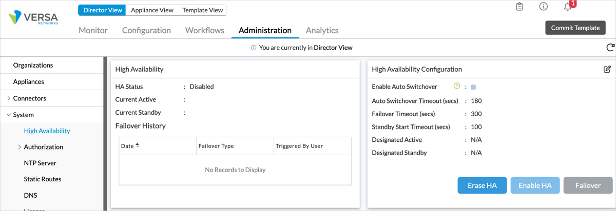
- Select the Administration tab in the top menu bar.
- Select System > High Availability in the left menu bar.
- For Releases 22.1.1 and later.
- In the High Availability Configuration pane, click the
 Edit icon. Enter information for the following fields.
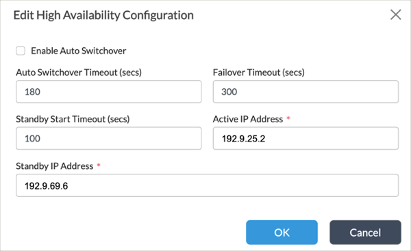
Field Description Active IP Address
Enter the IP address of the active Director node. When you enable HA, there are no restrictions on the IP address you choose. This means that you can choose the IP address of either the northbound or southbound interface. Whichever IP address you choose, ensure that it meets the firewall requirements described in Firewall Requirements. For more information about configuring Director nodes in HA mode, see Configure Systemwide Functions Standby IP Address
Enter the IP address of the standby Director node. As described above, there are no restrictions on which IP address you choose for the standby IP address. - Click OK.
- In the High Availability Configuration pane, select the Enable HA icon.
- In the High Availability Configuration pane, click the
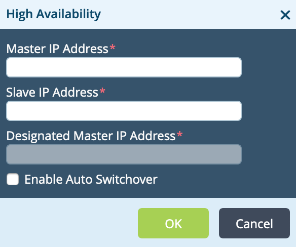
- For Releases 21.2 and earlier, in the High Availability pane, click the Edit icon. Enter information for the following fields, and then click OK.

Field Description Master IP Address Enter the IP address of the active Director node. When you enable HA, there are no restrictions on the IP address you choose. This means that you can choose the IP address of either the northbound or southbound interface. Whichever IP address you choose, ensure that it meets the firewall requirements described in Firewall Requirements. Slave IP Address Enter the IP address of the standby Director node. As described above, there are no restrictions on which IP address you choose for the standby IP address. Designated Master IP Address Enter the IP address of the designated active Director node. Enable Autoswitchover Click to enable automatic switchover to the standby Director node if the active node fails.
- HA status and configuration information displays in the main pane.

- To verify the HA status from the CLI, issue the request vnmsha actions command on the active and standby Versa Directors. Here, the active Versa Director is Director01. In the "vnmsha-details" section of the command output, check that the mode is "master" and that the management IP address is correct. In the "peer-vnmsha-details" section, check that the peer mode is "slave" and that the management IP address is correct.
Administrator@Director01$ cli
Output:

                        .---.,
            (   ``.
    _   \        )  __      ________ _____   _____
    (  `.   \   /   \ \    / /  ____|  __ \ / ____|  /\
    \   `. )    /       \ \  / /| |__  | |__) | (___   /  \
        \   |    /      \ \/ / |  __| |  _  / \___ \ / /\ \
        \   |   /           \  /  | |____| | \ \ ____) / ____ \
        \   |  /            \/   |______|_|  \_\_____/_/    \_\
        \  | /
            \_|/            ___ ___ ___ ___ ___ _____ ___  ___
                              |   \_ _| _ \ __/ __|_   _/ _ \| _ \
                            | |) | ||   / _| (__  | || (_) |   /
                              |___/___|_|_\___\___| |_| \___/|_|_\

Administrator connected from 10.161.0.11 using ssh on Director01
Administrator@Director01> request vnmsha actions status
status MASTER
[ok][2018-08-13 13:10:33]
Administrator@Director01> request vnmsha actions get-vnmsha-details fetch-peer-vnmsha-details true
status SUCCESS
vnmsha-details {
    mgmt-ip-address 10.192.98.10
    enabled true
    designated-master true
    mode master
    peer-vnmsha-details {
        peer-vnmsha-detail {
            mgmt-ip-address 10.192.98.11
            enabled true
            designated-master false
            mode slave
        }
    }
}
Administrator@Director01> exit
On the standby Director node, here Director02, check in the "vnmsha-details" section of the command output that the mode is "slave," that the management IP address is correct, and that this address matches the peer IP address on the active Versa Director. In the "peer-vnmsha-details" section, check that the peer mode is "master," that the management IP address is correct, and that this address matches the master address on the active Director node.
Administrator@Director02$ cli
Output:
            .---.,
            (   ``.
    _   \        )  __      ________ _____   _____
    (  `.   \   /   \ \    / /  ____|  __ \ / ____|  /\
    \   `. )    /       \ \  / /| |__  | |__) | (___   /  \
        \   |    /      \ \/ / |  __| |  _  / \___ \ / /\ \
        \   |   /           \  /  | |____| | \ \ ____) / ____ \
        \   |  /            \/   |______|_|  \_\_____/_/    \_\
        \  | /
            \_|/            ___ ___ ___ ___ ___ _____ ___  ___
                              |   \_ _| _ \ __/ __|_   _/ _ \| _ \
                            | |) | ||   / _| (__  | || (_) |   /
                              |___/___|_|_\___\___| |_| \___/|_|_\

Administrator connected from 10.161.0.11 using ssh on Director02
Administrator@Director02> request vnmsha actions status
status SLAVE
[ok][2018-08-13 13:12:01]
Administrator@Director02> request vnmsha actions get-vnmsha-details fetch-peer-vnmsha-details true
status SUCCESS
vnmsha-details {
    mgmt-ip-address 10.192.98.11
    enabled true
    designated-master false
    mode slave
    peer-vnmsha-details {
        peer-vnmsha-detail {
            mgmt-ip-address 10.192.98.10
            enabled true
            designated-master true
            mode master
        }
    }
}
Add a Static Route
Define a static route on the active Versa Director to provide an exit from the device when no other routes are available:
- In the active Director node, select the Administration tab in the top menu bar.
- In the left navigation bar, select System > Static Routes.

- For Releases 22.1.1 and later, you can add a static route to the standby or active Director node.
- Click the drop-down menu in the main pane, and then select a node.

- Click the + Add icon. In the Add Static Route popup window, enter information for the following fields:
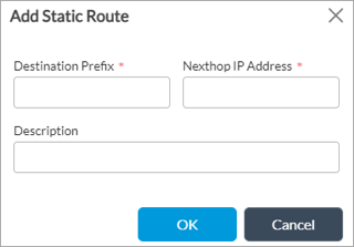
Field Description Destination Prefix IP address and prefix that is reachable using the static route. Next-Hop IP Address IP address of the router or gateway to reach the destination.
- Click OK.
- Click the drop-down menu in the main pane, and then select a node.
- For Releases 21.2 and earlier:
- Click the
Add icon. In the Add Static Route popup window, enter information for the following fields.
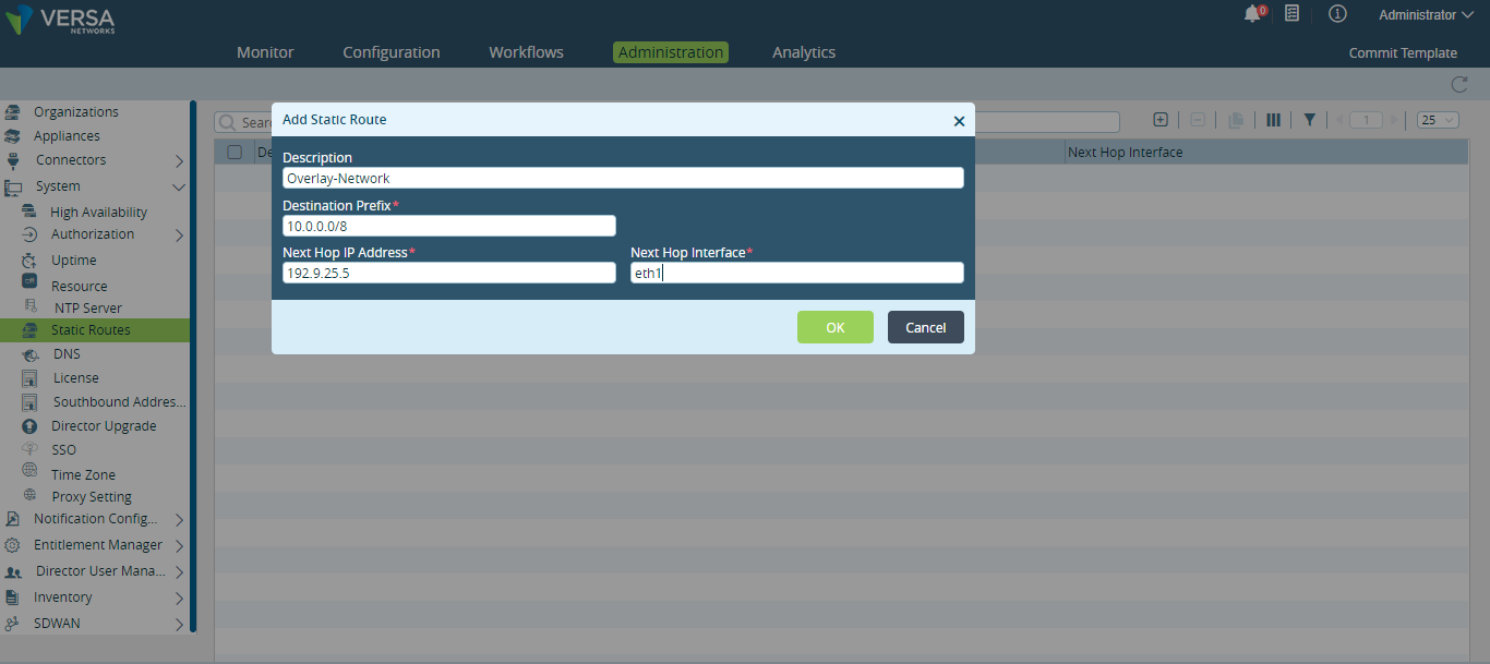
Field Description Destination Prefix IP address and prefix that is reachable using the static route. Next-Hop IP Address IP address of the router or gateway to reach the destination. Next-Hop Interface Name of the Versa Director interface through which the next-hop IP address is reachable. - Click OK.
- Click the
Change Default Passwords
Director installation and configuration procedures automatically create the following accounts:
- Shell user accounts
- aaaadmin—Account used for CLI and shell access for users outside the /etc/passwd system, such as provider users.
- admin—Account that is typically used in procedures to run shell commands.
- Administrator—Account typically used for initial set up of a Director node.
- osupgrade
- versa—Account that is required to run specific commands. When this is necessary, procedures include commands to switch your identity to user versa.
- Provider user account
- Administrator
Please consult Versa technical support for default credentials.
Note: In a production environment, it is recommended that you change the default passwords.
This section describes how to change passwords for shell and provider user accounts.
To change the default password for shell user accounts on a Director node:
- Log in to the shell on the Director node.
- Change your identity to root, and then issue the passwd command on the usernames. The following example changes the password for the versa shell account.
admin@Director$ sudo su root
root@Director# passwd versa
root@Director# exit
admin@Director$
To change the password for the Administrator provider account:
- Log in to the Director GUI.
- Select Administration > System > Director User Management > Provider Users. The main pane displays the provider user account information.

- Click the box to the left of username Administrator. The Reset Password icon activates.
- Click the Reset Password icon. The Reset Password popup window displays.
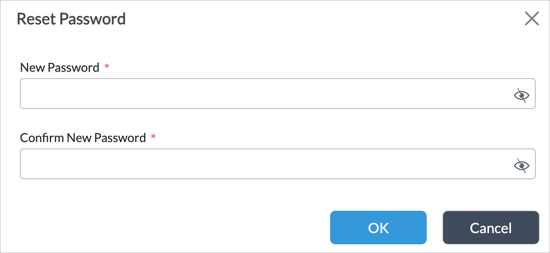
- In the New Password and Confirm New Password fields, enter a password.
- Click OK.
Add a Standby Director Node to an Existing Single-Director Headend
To add a standby Director node to an existing single-Director headend, follow the procedure for the second Director node in Set Up Director, above. Then perform the following tasks to add the standby Director node to Analytics cluster configurations:
- Resynchronize certificates between the Director and Analytics nodes.
- Update /etc/host file entries on the Analytics nodes.
- Register the standby Director node in the Analytics application.
- Reconfigure Analytics exporter rules that forward alarms to Director nodes.
This section describes how to update Analytics cluster configurations when you add a standby Director node to an existing single-Director headend.
To resynchronize certificates and register the standby Director node:
- Ensure that the certificate on the active Director node includes the hostname of the standby Director node.
admin@Director$ sudo su - versa
versa@Director$ /usr/lib/jvm/java-11-openjdk-amd64/bin/keytool --printcert -v -file versa_director_client.cer
Owner: CN=Director1, OU=VersaDirector, O=versa-networks, ST=California, C=US
Issuer: L=Santa Clara, ST=California, C=US, OU=VersaDirector, O=versa-networks, CN=versa-director1
Serial number: 1
Valid from: Thu Jul 25 06:11:30 UTC 2019 until: Sun Jul 22 06:11:30 UTC 2029
Certificate fingerprints:
SHA1: E6:06:8F:F2:6E:77:2C:1C:88:30:60:8B:57:5A:AD:58:E2:6E:66:9F
SHA256: 68:D8:0C:EE:74:F8:DB:2E:FC:67:DE:32:C8:1E:18:FC:16:75:79:68:60:15:0D:0D:59:25:CB:BE:20:04:79:EF
Signature algorithm name: SHA256withRSA
Subject Public Key Algorithm: 2048-bit RSA key
Version: 3
Extensions:
#1: ObjectId: 2.5.29.19 Criticality=false
BasicConstraints:[
  CA:false
  PathLen: undefined
]
#2: ObjectId: 2.5.29.17 Criticality=false
SubjectAlternativeName:[
  DNSName: Director1
  DNSName: Director2
]
- On the active Director node, resynchronize certificates to the nodes in the Analytics cluster by executing the vnms-cert-sync.sh script. This script prompts you to enter the name of the Analytics cluster connector, which it refers to as the VAN Cluster Name. To find the Analytics cluster connector name in the Director GUI, in Director view, select Administration > Connectors > Analytics Cluster in the left menu bar. The Cluster Name column displays the connector names.
versa@Director$ /opt/versa/vnms/scripts/vnms-cert-sync.sh --sync
versa@Director$ exit
admin@Director$
- On each node in the Analytics cluster, log in to the shell, and then add an entry for the standby Director node to the /etc/hosts file. The entry must include the host value from the certificate.
Caution: If you are using a wildcard certificate, use the full domain name when you create an entry in the /etc/hosts file. For example, if the CN value is *.utt.com, use hostnames Director1.utt.com and Director2.utt.com. Enter the same full domain name (for example, Director1.utt.com) when you register Versa Director on the Analytics Authentication page.
admin@Analytics$ cat /etc/hosts
127.0.0.1 localhost
192.10.10.56 Analytics
10.192.215.145 versa-director01 Director1
10.192.215.146 versa-director02 Director2

# The following lines are desirable for IPv6 capable hosts
::1     localhost ip6-localhost ip6-loopback
ff02::1 ip6-allnodes
ff02::2 ip6-allrouters
- In the Director GUI, register the standby Director node in the Analytics application:
- In Director view, select the Analytics tab. For Releases 22.1.1 and later, hover over the Analytics tab, and then select a node from the Analytics cluster. For Releases 21.2 and earlier, select a cluster node in the horizontal menu bar.
- Select Administration > Configurations > Authentication in the left menu bar. The main pane displays the hostname of the standby Director node.
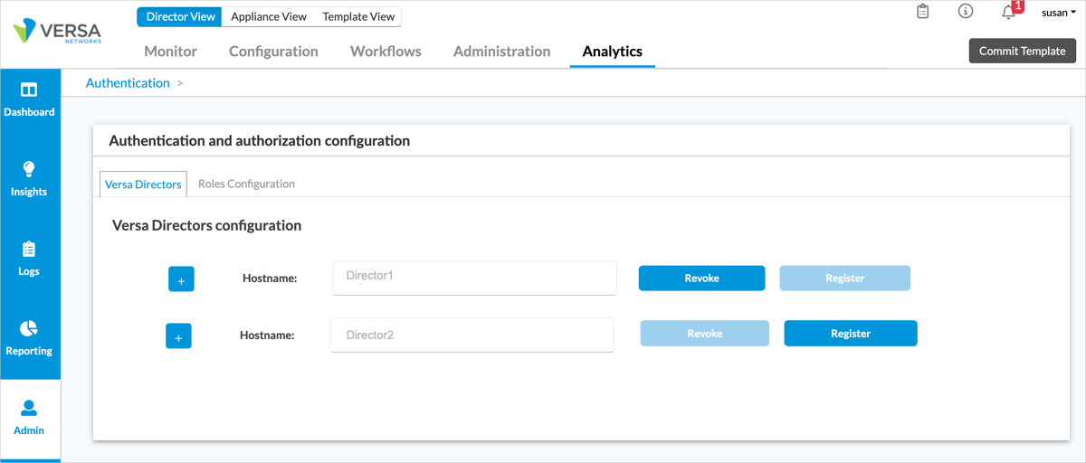
- Select the Register icon after the hostname of the standby Director node.
- On each Analytics node that collects logs, reconfigure the exporter rule that exports alarm logs to Director nodes to include the standby node. For information about how to configure an exporter rule to stream alarm logs to Director nodes, see Export Alarm Logs to Director Nodes.
- If your topology contains multiple Analytics clusters, repeat Steps 2 through 5 for each cluster.
Set Up Analytics
The Analytics platform is a cluster of Analytics nodes that reside in one or more data centers or geographic regions. A standard Analytics cluster consists of one or more Analytics nodes, some or all of which contain search and analytics engines. Nodes in a standard Analytics cluster can receive and process logs from Versa Operating SystemTM (VOSTM) devices. The logs can be processed in the cluster or can be exported to other systems.
To set up a standard Analytics platform, you enable the following components on the Analytics nodes:
- Log collector exporter—The log collector exporter is a server that receives logs in IPFIX format from the VOS devices. The log collector parses the logs and stores these raw logs in its local filesystem, in the /var/tmp/log directory. In this directory, the logs for each tenant or appliance are stored in a separate subdirectory. The raw log files are periodically archived in the /var/tmp/archive directory. The raw logs are formatted and sent to a non-SQL (NoSQL) database, and simultaneously the data is indexed by the search engine so that it is available to be used by web services. You can also configure the log collector exporter to send the logs to one or more third-party collectors. To have the log collector exporter stream logs to Director nodes, you must configure a remote collector for the Director nodes. For more information, see Configure Log Collectors and Log Exporter Rules.
- Versa Analytics driver—The Versa Analytics driver is a program that performs extract, transform, and load (ETL) operations on the log files in the /var/tmp/log directory and populates the database and search engine datastores. The driver moves processed log files to backup directories where they are periodically archived.
- Datastore, and search and analytics engines—The datastore provides storage, and the search and analytics engines provide search and analytics services. The Cassandra database is used for data storage and for the analysis functionality, and it supports automatic replication of data to one or more nodes of the cluster. The Solr search platform is used for the search functionality. In production networks, search and analytics workflows are performed in separate sets of nodes. This means that search data is stored and replicated only to search nodes (nodes whose personality is set to "search") and analytics data is stored and replicated only to nodes whose personality is set to "analytics."
- Analytics application—The Analytics application interfaces with Director to provide authentication and authorization. It also provides RESTful-based services to the Analytics user interface and to third-party custom applications.
An Analytics node can operate in one of the following modes:
- Default—In the default mode, all three of the Analytics components are enabled on a node. Specifically, the log collector and exporter and the Analytics applications are both enabled on the node, and either search or analytics is enabled, because search and analysis are performed on separate nodes. This requirement means that an Analytics cluster must have at least two nodes, one that is configured with the search personality and one configured with the analytics personality. To provide HA for the data stored in the Analytics datastore, the Analytics cluster should have at least two search nodes and two analytics nodes.
For default mode, you run the standard Analytics software image on the node. Default operation requires high CPU, memory, and disk resources. For best performance, it is recommended that you use bare-metal servers for the Analytics nodes. For more information about hardware requirements, see Hardware and Software Requirements for Headend. - Log forwarder—In log forwarder mode, the local instance of the Analytics node does not run the datastore function. Instead, data is stored on remote or centralized Analytics engines, and the local node connects to these remote engines to update the database. Log forwarder mode is useful when data must remain within a country or regional boundary for compliance purposes. This mode is also useful to scale the analytics solution for large-scale networks as you are moving the client functionality out of datastore nodes.
For log forwarder mode, you run the standard Analytics software image even though you are not using a local database. In this mode, you can use either a bare-metal or a VM server, because the requirements for CPU, memory, and disk resources are relatively low. - Lightweight log collector—In this mode, data is not stored in the Analytics engines. Instead, you enable only the log collector exporter component, and the exporter streams logs to third-party collectors. In this mode, logs are also archived in the local filesystem.
For lightweight log collector, you run a trimmed down version of the Analytics software image, which does not include the database and the application. You can use either a bare-metal or a VM server, because the requirements for CPU, memory, and disk resources are relatively low.
The following figure shows an example of a four-node Analytics cluster:
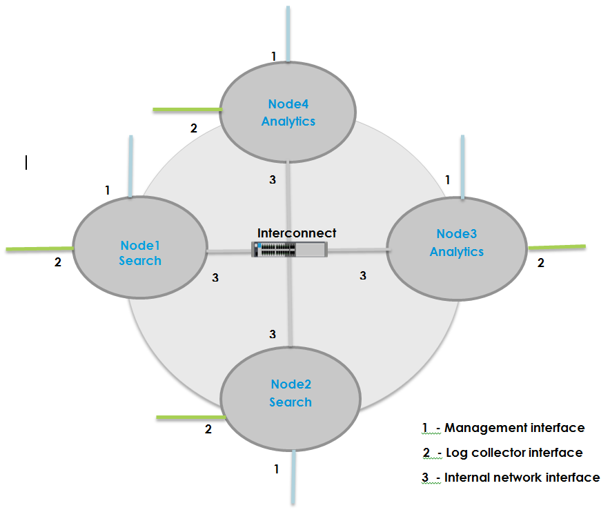
It is recommended that each Analytics node have the following interfaces:
- Management interface—This is the eth0 interface, which is the northbound interface.
- Interface used for local collectors—This is the eth1 interface, which is the southbound interface.
- Internal network interface—This is the eth2 interface and is used to interconnect the individual Analytics nodes in the cluster. It is recommended that you configure eth2 as the internal network interface, but you can use the eth1 interface for this purpose.
Note: It is required that the internal network interface on all nodes containing the search engine or Analytics database be in the same LAN since continual database synchronization and replication occurs over this interface. You configure the internal network interface using field listen_address in the clustersetup.conf file in Set Up an Analytics Cluster, below.
Aggregator Nodes
For Releases 22.1.1 and later, you can configure a separate, independent Analytics node to consolidate data from Analytics clusters. This node, called an Analytics aggregator node, consolidates and aggregates tenant data from multiple standard Analytics clusters, which are referred to as child clusters when in this configuration.
You can set up an Analytics aggregator nodes for one of the following scenarios:
- When a single standard Analytics cluster manages more than 2,500 VOS devices
- When a single tenant is managed by more than one standard Analytic cluster
- When you want to install multiple regional Analytics clusters
The aggregator node consolidates and aggregates Analytics data from standard Analytics clusters (called child clusters), thus allowing you to view data and reports from a single Analytics node. (Without the aggregator node, you would have to switch between clusters to view data and reports.) An aggregator node maintains only limited information about its child clusters, including tenant, VOS device, and resource mappings, so it requires fewer disk and computational resources than a standard Analytics cluster. In Versa Concerto, you can combine multiple aggregator nodes into an aggregator cluster to provide redundancy and load balancing.
For information about configuring aggregator nodes, see Configure Analytics Aggregator Nodes.
Set Up an Analytics Cluster
To set up an Analytics cluster, you do the following:
- Configure an Analytics connector
- Expand disk storage on Analytics nodes
- Configure software on Analytics nodes. In all releases, you can configure the Analytics node software by running a script from the shell on the Director node. In Releases 23.1.1 and later, you can alternatively configure the Analytics node software from the Director UI.
- Configure Node Types in the Analytics Application
- Configure a DNS Name Server
- Configure NTP on all Analytics nodes.
- (Optional) Configure SMTP on Analytics nodes so that they can email Analytics reports.
- (Optional) Perform Analytics Hardening
Configure an Analytics Connector
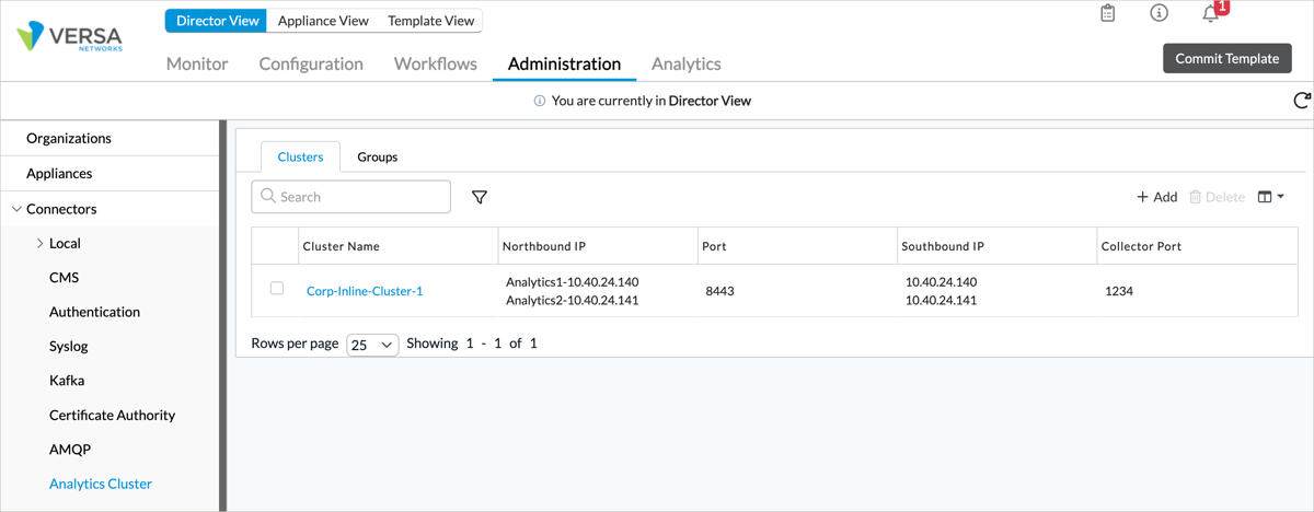
The Analytics tab in the Director UI must communicate with the Analytics application in the Analytics cluster. To enable this communication, you configure an Analytics cluster connector in Director.
To configure an Analytics cluster connector:
- Log in to Versa Director.
- In Director view, select the Administration tab in the top menu bar.
- Select Connectors > Analytics Cluster in the left menu bar.
- Click the
 Add icon. In the Add Analytics Cluster popup window, enter information for the following fields.
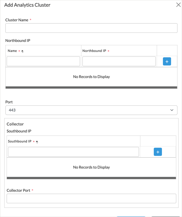
Field Description Cluster Name (Required) Enter a name for the cluster. Northbound IP (Table) Enter information about the northbound interfaces of the nodes in the Analytics cluster. - Name (Required)
Enter a name for the northbound interface. - Northbound IP (Required)
Enter the IP address of the northbound interface.  Add icon
Click the Add icon to add the northbound IP address.Port (For Releases 22.1.1 and later.) Select the port number to use for the northbound connection. Connector Port (For Releases 21.2 and earlier.) Select the port number to use for the northbound connection. Collector (Table) Enter information about the Versa Analytics cluster collector.
- Southbound IP (Required)
Enter the IP address of the southbound interface. - Add icon
Click the Add icon to add the IP address.Collector Port (Required) Enter the port number to use for the Analytics local collector. This is typically port 1234.
- Click OK.
Expand Disk Storage on Analytics Nodes
For Analytics nodes that are running on virtual machines (VMs), typically log-forwarder type nodes, you must expand disk storage to provide the recommended amount. For recommended storage, see Hardware and Software Requirements for Headend.
The size of the root filesystem increases over time. To increase the available storage and expand the size of the root filesystem on Analytics nodes running on VMs, follow the procedures in Expand Disk Storage for Analytics Nodes.
Configure Analytics Cluster Nodes
To set up Analytics nodes, you do the following:
- Configure an Analytics connector
- Expand disk storage on Analytics nodes
- Configure software on Analytics nodes. In Releases 23.1.1 and later, you can configure software from the Director UI. In all releases, you can configure Analytics software by running a script from the shell on the Director node.
- Configure Node Types in the Analytics Application
- Configure a DNS Name Server
- Configure NTP on all Analytics nodes.
- (Optional) Configure SMTP on analytics so that they can email Analytics reports.
- (Optional) Perform Analytics Hardening
Configure Analytics Cluster Nodes from the Director UI
For Releases 23.1.1 and later.
For information about setting up Analytics cluster nodes from the Director UI, see Configure Analytics Cluster Nodes from the Director UI.
Configure Analytics Cluster Nodes Using a Script
To set up Analytics cluster nodes using a script, you edit the configuration file for the cluster deployment script on the Director node and then run the deployment script . The cluster deployment script configures individual nodes in the Analytics cluster and initiates cluster processes.
Note: You must perform network interface configuration on all Analytics cluster nodes prior to running the cluster deployment script on the Director node. The script requires access to the interfaces to interact with Analytics cluster nodes.
For Releases 21.1.x, first you must download the cluster deployment script. For Releases 21.2.x and later, the cluster deployment script is integrated into the Director software packages, so you do not have to download it.
To set up an Analytics cluster:
- Log in to the shell on each Analytics node, and then verify that certificates are installed.
- Verify that files are present in the /opt/versa/var/van-app/certificates directory:
admin@Analytics01$ ls /opt/versa/var/van-app/certificates
If the directory is empty, run the following script:
admin@Analytics01$ sudo /opt/versa/scripts/van-scripts/van-cert-install.sh
-
On each node of the Analytics cluster, edit the /etc/hosts file to add entries for the hostnames of the Analytics cluster nodes. The hostnames must map to the internal network interface on the nodes. This interface maps to the listen_address you configure in Step 13, below. Adding these entries is required to facilitate effective communication between the nodes of the Analytics Cluster.
The following example shows the contents of the /etc/hosts file on node Analytics01 in a four-node Analytics cluster. The file has entries for each of the four nodes (Analytics01, Analytics02, Analytics03, and Analytics04), and the corresponding IP address for each southbound interface (192.168.1.101, 192.168.1.102, 192.168.1.103, and 192.168.1.104, respectively).admin@Analytics01$ cat /etc/hosts 127.0.0.1 localhost # The following lines are desirable for IPv6 capable hosts ::1 localhost ip6-localhost ip6-loopback ff02::1 ip6-allnodes ff02::2 ip6-allrouters 192.168.1.101 Analytics01 192.168.1.102 Analytics02 192.168.1.103 Analytics03 192.168.1.104 Analytics04
- Log in to the shell on the Director node.
- Access the clustersetup.conf file:
- (For Releases 22.1.4 and later.) The file clustersetup_def.conf is a template for the clustersetup.conf file and contains the most recent fields. Use this template to create the clustersetup.conf file. Issue the following commands to copy the template and name the copied file clustersetup.conf.
admin@Director01$ cd /opt/versa/vnms/scripts/van-cluster-config/van_cluster_install
admin@Director01$ cp clustersetup_def.conf clustersetup.conf
- (For Releases 21.1.1 and later, and 22.1.1, 22.1.2, and 22.1.3.) The cluster configuration file is located on the Director node at /opt/versa/vnms/scripts/van-cluster-config/van_cluster_install/clustersetup.conf.
- Edit the clustersetup.conf file, adding values for the parameters listed below. This file contains other parameters that are for internal use only. Do not modify the values for these parameters, and do not delete them from the file.
admin@Director01$ cd /opt/versa/vnms/scripts/van-cluster-config/van_cluster_install
admin@Director01$ nano clustersetup.conf
Parameter Description cluster_name Name for the cluster. This same name is used for all the nodes of the cluster. cluster_size Number of nodes in the cluster: 2, 4, or 6. This number does not include log-forwarder type nodes.
(For Releases 22.1.4 and later.) If you set this value to 4 or 6, you must assign three nodes of personality search or analytics to be zookeeper nodes using the zookeeper_node parameter, described below.
forwarder_count Number of log forwarders in the cluster. In default mode, this value is 0. cluster_type (For Releases 22.1.1. and later.) Cluster type:
- aggregate
- standard
Use clustersetup.conf to configure standard cluster nodes only. To configure an aggregator node, see Configure Analytics Aggregator Nodes.
ntp_servers (For Releases 22.1.4 and later.) Comma-separated list of network time protocol (NTP) servers. NTP ensures time synchronization between Analytics nodes and is required. You must include at least one NTP server.
Note: If the ntp_servers entry is not present in the clustersetup.conf file, edit the file and enter it manually. The following sample entry lists 4 NTP servers:
ntp_servers: 0.ubuntu.pool.ntp.org, 1.ubuntu.pool.ntp.org, 2.ubuntu.pool.ntp.org, 3.ubuntu.pool.ntp.org
director_count Number of Director nodes that are communicating with the Analytics nodes. If the Director is operating in standalone mode, enter 1. If the Director is in active-standby mode, enter 2. - In the clustersetup.conf file, add values for Director nodes. Each Director node section of the file is preceded by [VERSA-DIR-n], where n is the Director node number. For each VERSA-DIR-n section, enter values for the following fields:
username Enter the login name for the Director node. The default login name is Administrator. You will enter the password for this account at the password prompt when you run the van_cluster_installation.py script.
rpc_address The management (eth0) address of the Director node. This address or the listen address must be reachable from all the nodes in the Analytics cluster.
listen_address IP address of the internal network interface address for connecting to Analytics nodes.
- In the clustersetup.conf file, add values for search-type, analytics-type, and standalone nodes. Each search-type, analytics-type, and standalone node section of the file is preceded by [VAN-NODE-n], where n is the Analytics node number. For each VAN-Node-n section, enter values for the following fields.
username Enter the shell login name for the Analytics node. Please consult Versa technical support for default credentials. You can enter the password for the account in the password field, or you can enter it when you run the van_cluster_installation.py script.
ui_password (For Releases 22.1.4 and later.) Enter a password for the Analytics application admin account. If you leave this field blank, you will be prompted to enter the password when you run the van_cluster_installation.py --post-setup command in a later step in this procedure. Note that the shell and Analytics applications admin accounts are separate accounts. For more information about the Analytics application, see Versa Director Nodes and Analytics Clusters in Versa Analytics Configuration Concepts.
mode Mode in which the Analytics node operates:
- cluster—Set up the node as part of a standard Analytics cluster.
- standalone—Set up a standalone node for proof-of-concept (POC) configurations.
hostname Name to identify the Analytics nodes in the cluster.
- (For Releases 22.1.1 and later.) The hostname of the node.
- (For Releases 21.2 and earlier.) Each of the nodes is identified by this name followed by a number. For example, if you specify the hostname "Analytics," the script names the first node "Analytics01," the second node "Analytics02," and so on.
personality Role of the Analytics node. Based on the number of nodes in the cluster (as specified in the cluster_size parameter), the script configures the first half of the nodes with the analytics personality and the second half of the nodes with the search personality. In a four-node cluster, node01 and node02 are analytics nodes, and node03 and node04 are search nodes.
- analytics—Enable the analytics database on the node.
- search—Enable the search engine on the node.
- standalone—Enable both the analytics database and search engine on the node. This personality is useful for POC configurations.
rpc_address IP address of the management (northbound) interface, which is the eth0 interface. listen_address IP address of the internal network interface. All internal network interfaces for a cluster must be on the same LAN. collector_address IP address of the Analytics local collector. The setup script automatically sets up a local collector at this address on the node. If this field is commented (preceded by a # character), no local collector is configured. collector_port Port number to use to connect to the local collector. You can comment this field if no local collector IP address is included in the collector_address field. zookeeper_node
(For Releases 22.1.4 and later.) Search-type and analytics-type nodes within an Analytics cluster run the Apache Zookeeper service to coordinate applications. Set this value to true to configure the node as a zookeeper.
The following table describes how to configure the Zookeeper parameter for Analytics clusters with varying numbers of analytics-type and search-type nodes.
Number of Nodes Description Zookeeper Settings 1 1 standalone node Set to true for the node. 2 1 search-type and 1 analytics-type node Set to true for both nodes. 4 2 search-type and 2 analytics-type nodes Set to true on 2 analytics-type nodes and 1 search-type node. Set to false on the remaining node. 6 or more 2 search-type nodes with the remaining nodes configured as analytics-type nodes Set to true for 3 or 5 of the nodes. For typical deployments, 3 zookeepers are sufficient. Set this value to false on the remaining nodes. Note: If zookeeper_node entries are not present in the clustersetup.conf file, edit the file and add them manually for each VAN-NODE-n that you configure. In the following example, zookeeper_node is set to true for VAN-NODE-2.
[VAN-NODE-2] username: versa #password: mode:cluster hostname:van-search-01 personality:search rpc_address:10.10.10.12 listen_address:192.168.1.2 collector_address:192.168.2.2 collector_port:1234 zookeeper_node:true - In the clustersetup.conf file, add values for log forwarder nodes. Each forwarder node section of the file is preceded by [FORWARDER-NODE-n], where n is the node number. For each FORWARDER-NODE-n section, enter values for the following fields.
username Enter the login name for the Analytics node. Please consult Versa technical support for default credentials. You can enter the password for the account in the password field, or you can enter it when you run the van_cluster_installation.py script. mode Enter cluster.
hostname The hostname of the node.
personality Enter forwarder.
rpc_address IP address of the management (northbound) interface, which is the eth0 interface. listen_address IP address of the internal network interface. All internal network interfaces for a cluster must be on the same LAN. collector_address IP address of the Analytics local collector. The setup script automatically sets up a local collector at this address on the node. This field is required for log forwarder nodes. collector_port Port number to use to connect to the local collector. This field is required for log forwarder nodes. - (For Releases 22.1.3 and later) In the clustersetup.conf file, add allowed subnets to the [IPTABLE-WHITELIST] section. The internal and management subnets are allowed access by default, and in this section you configure additional access. For access to internal interfaces on Analytics clusters, add entries in the section labeled INTERNAL. For access to management interfaces on Analytics clusters, add additional IP addresses and/or subnets in the section labeled MANAGEMENT.
For example, the following entries add subnets 10.10.10.0/24 and 10.20.20.0/24 in the allowed sources list for inter-cluster access. This can be used for additional collector subnets. Additionally, 2.2.2.2 and 1.1.1.1 are added to allow source IP addresses for management access.[IPTABLE-WHITELIST] INTERNAL: 10.10.10.10, 10.20.20.1/24 MANAGEMENT: 2.2.2.2, 1.1.1.1
- Save the changes you made to the clustersetup.conf file.
- Change your identity to user versa:
admin@Director01$ sudo su versa
versa@Director01$
- Run the cluster installation script. When the script prompts, enter the appropriate values. (To bypass the prompts, include the --force option.)
versa@Director01$ sudo ./van_cluster_installer.py
This script does the following:
- Based on the parameter values you configured in the clustersetup.conf file, generates one Analytics configuration setup file, vansetup.conf, for each node in the cluster. Do not modify the contents of the vansetup.conf files.
- Copies the vansetup.conf file and all required installation files to each Analytics node in the cluster.
- Installs the Analytics certificate on the Director node.
- Executes the vansetup.py installation script on each Analytics node.
-
Run the cluster installation script a second time, including the --post-setup option, to complete the setup of the Analytics cluster.
If HA is enabled on the Director node, and if you have not already generated certificates or are not using CA signed certificates, issue the following command, which generates a new certificate during the post-setup process:
versa@Director01$ sudo ./van_cluster_installer.py --post-setup --gen-vd-cert
If a valid self-signed certificate is already present on the Director node (with the correct hostnames mapped to the CN and SAN fields of the certificate), or if a CA signed certificate is present, issue the following command:
versa@Director01$ sudo ./van_cluster_installer.py --post-setup
This script does the following:
- Connects to each node in the cluster and configures the node.
- Installs the Director certificate on each node.
- Registers the Director hostnames on each node.
- Configures local collectors, using the IP address in the collector_address parameter and the port number in the collector_port parameter.
Note that for a 4-node or 6-node Analytics cluster, it can take up to 30 minutes for the cluster installation script to set up the nodes in the cluster.
- (For Releases 21.1.1 and later.) Run the cluster installation script with the --secure option to enable encrypted communication between various database components. This option is required when the Analytics node is exposed to public networks.
versa@Director01$ sudo -u versa ./van_cluster_installer.py --secure
The script enables secure communication on the following components:
- Cassandra
- Client communication secure port: 9042
- Internode communication secure port: 7001
- Solr
- Client communication secure port: 8983
- Internode communication secure port: 8983
- Versa Analytics driver
- REST API secure port: 5000
- Versa Analytics monitor
- REST API secure port: 5010
- Versa LCED (log collector exporter)
- REST API secure port: 8008
- ZooKeeper
- Internode communication secure ports: 2888, 3888
- Verify that the Director GUI can access the Analytics application on the node. To do this, in the Director GUI, select the Analytics tab.
- (For Releases 22.1.1 and later.) Hover over the Analytics tab, and then select a node in the newly configured Analytics cluster.
- (For Releases 21.2 and earlier.) Select a node in the drop-down list in the horizontal menu bar.
- If the Director GUI cannot connect to the Analytics application, see Troubleshoot Analytics Access and Certificate Issues.
- To configure additional Analytics clusters, repeat Steps 1 through 20. You must also add an Analytics connector for the additional cluster. See Configure an Analytics Connector, above.
- To configure a cluster in active-active or active-backup mode with another cluster, see Configure a Secondary Cluster for Log Collection.
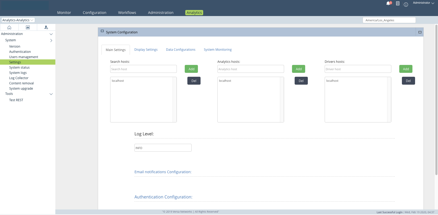
Configure Node Types in the Analytics Application
In the Analytics application, you identify the type or types of each node in each Analytics cluster. You can access the Analytics application from the Analytics tab in the Director GUI.
To identify Analytics cluster node types:
- In Director view, select the Analytics tab in the top menu bar.
- Select Administration > System > System Settings in the left menu bar, and then select the Main Settings tab. The System Configuration screen displays.

- For search-type nodes, select the + Add icon next to the Search Hosts field, and then enter the IP address of the node. If the node also performs log collection, add its collector address in Step 5.
- For analytics-type nodes, select the + Add icon next to the Analytics Hosts field, and then enter the IP address of the node. If the node also performs log collection, add its collector address in Step 5.
- For nodes that perform log collection, select the Add icon next to the Driver Hosts field, and then enter the IP address. This is the collector_address entry from the cluster_setup.conf file.
- Click Save.
- Select Administration > System Status > Log Collector Exporter in the left menu bar. The Log Collector Configuration screen displays.

- In the Driver Hosts drop-down menu, verify that the driver hosts that you configured in Step 5 are listed.
Configure a DNS Name Server
Configure a DNS name server on each Analytics node by editing the base file in the /etc/resolvconf/. You do this from the shell.
-
Configure the IP address of the DNS name server:
admin@Analytics$ sudo vi /etc/resolvconf/resolv.conf.d/base
nameserver x.x.x.x
For example:
admin@Analytics$ sudo vi /etc/resolvconf/resolv.conf.d/base
nameserver 8.8.8.8
-
Update the configuration file to save the name server entry:
admin@Analytics$ sudo resolvconf -u
-
Verify the configuration. For example:
admin@Analytics$ ping www.google.com
PING www.google.com (216.58.214.4) 56(84) bytes of data.
64 bytes from lhr26s05-in-f4.1e100.net (216.58.214.4): icmp_seq=1 ttl=117 time=15.4 ms
64 bytes from lhr26s05-in-f4.1e100.net (216.58.214.4): icmp_seq=2 ttl=117 time=10.5 ms
Configure NTP
To ensure that the time is synchronized on all the Analytics nodes, you must configure NTP on each of the nodes. For Releases 21.2.3 and later, you can configure NTP on Analytics nodes using the shell or CLI. For Releases 21.2.2 and earlier, configure NTP using the shell. For Releases 22.1.2 and later, you can optionally configure MD5 or SHA1 authentication for NTP servers with authentication enabled.
Configure an NTP Server
To configure an NTP server:
-
Display a list of available timezones:
admin@Analytics$ timedatectl list-timezones
- Set the timezone:
admin@Analytics$ sudo timedatectl set-timezone timezone
For Example:admin@Analytics$ sudo timedatectl set-timezone Africa/Cairo
Note that the default timezone is Americas/Los_Angeles. To change the default, edit the /etc/timezone file.
-
Verify that the timezone is correct:
admin@Analytics$ timedatectl
- Set the local time. For Releases 21.2.3 and later, issue the following command from the CLI on the Analytics node:
admin@Analytics% set system ntp server your.ntp.server.local prefer iburst
For Releases 21.2.2 and earlier, set the local time using the shell by adding the following line to the /etc/ntp.conf file:server your.ntp.server.local prefer iburst
For a list of available time servers, see https://www.ntppool.org/zone/@.
- To set the local time using the CLI, issue the following commands:
admin@Analytics$ cli
admin@Analytics> configure
admin@Analytics% set system ntp server your.ntp.server.local iburst
admin@Analytics% commit
admin@Analytics% exit
admin@Analytics> exit
-
Verify that the NTP time server is correct:
admin@Analytics$ ntpq -pn
- If any of the Analytics nodes are virtual machines (VMs), ensure that NTP is configured correctly on the host hypervisor device.
Configure MD5 or SHA1 Authentication for an NTP Server
For Release 22.1.2 and later.
Versa Analytics clusters support both MD5 and SHA1 hash encryption algorithms for NTP, and you can choose to use MD5 or SHA1 for authentication. To do this, you associate an NTP server with a key, which is identified by a key number. You then set the hash type and value for the key, and identify the key as trusted.
Note that the following optional procedure is for NTP servers with authentication enabled.
To configure MD5 or SHA1 authentication for an NTP server, issue the following commands.
admin@Analytics$ cli
admin@Analytics> configure
admin@Analytics% set system ntp server <server-ip> key 1
admin@Analytics% set system ntp key 1 type ?
Description: Authentication type
Possible completions:
  [md5]
  md5  - MD5 authentication
  sha1 - SHA-1 authentication
admin@Analytics% set system ntp key 1 type sha1
admin@Analytics% set system ntp key 1 value <sha1-key>
admin@Analytics% set system ntp key 1 trusted true
admin@Analytics% commit
Configure SMTP
To allow an Analytics node to send reports and email notifications, you configure the SMTP on the Analytics node. To allow an Analytics cluster to send reports and email notifications, you must configure SMTP on all the nodes in the cluster.
To configure SMTP:
- In Director view, select the Analytics tab in the top menu bar.
- For Releases 22.1.1 and later:
- Select Administration > Configurations > Settings in the left menu bar. The following screen displays.

- Select the Email Configuration tab, and then enter information for the following fields.

Field Description SMTP Host Enter the hostname of the SMTP server. SMTP Port Enter the port number of the SMTP server. Username Enter the username to use to connect to the SMTP server. Password Enter the password to use to connect to the SMTP server. Sender Email Enter the email address to place in the From: field of the email. System Email Notifications Enter the email address to which to send Analytics monitoring notifications. If you enter more than one email address, separate them with commas. SSL, TLS Click to enable SSL or TLS security on the email connection. - Select Save Configuration.
- Select Administration > Configurations > Settings in the left menu bar. The following screen displays.
- For Releases 21.2 and earlier:
- Select Administration > System > System Settings in the left menu bar. The following screen displays.
- Click the Email Notifications Configuration link to display the configuration fields. Enter information for the following fields.
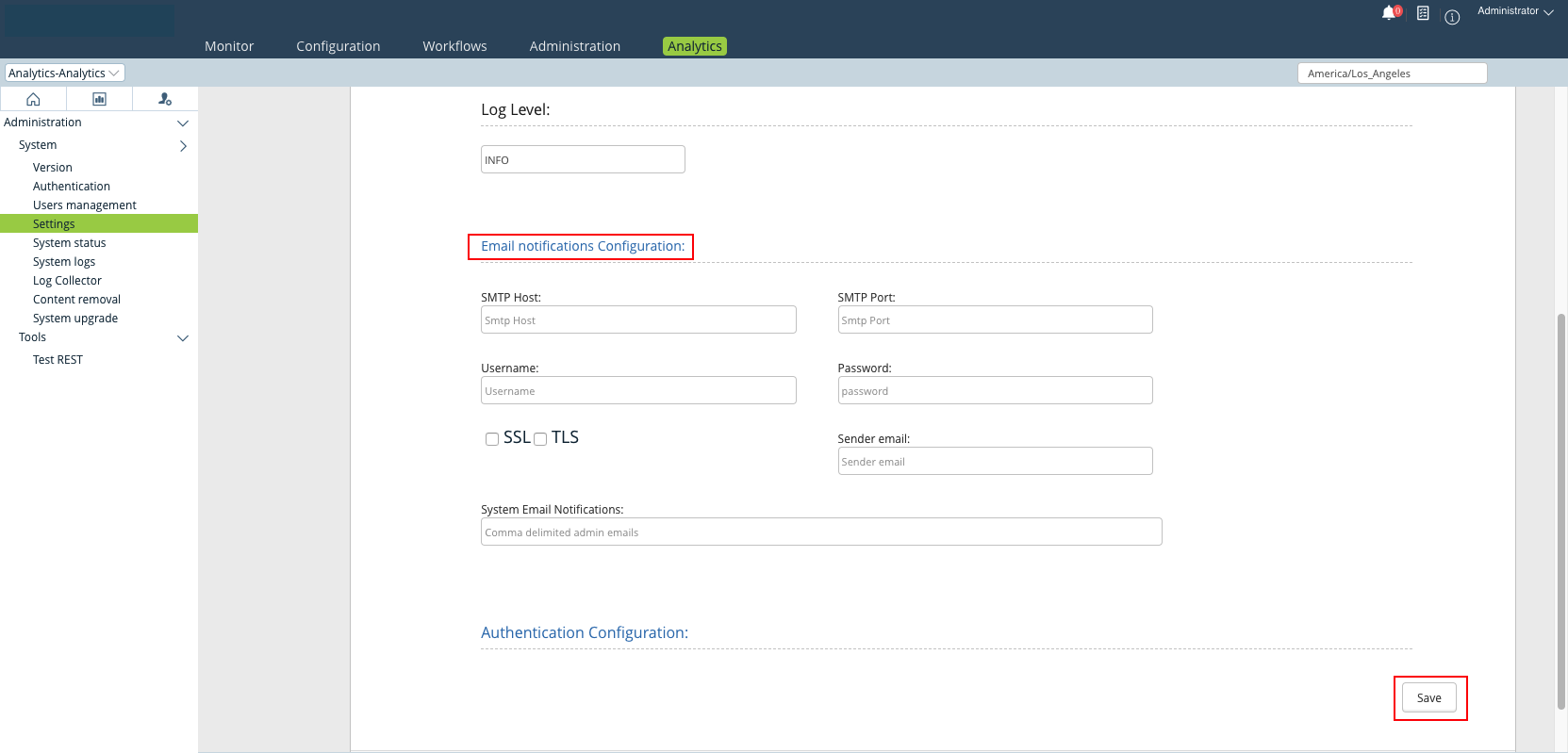
Field Description SMTP Host Enter the hostname of the SMTP server. SMTP Port Enter the port number of the SMTP server. Username Enter the username to use to connect to the SMTP server. Password Enter the password to use to connect to the SMTP server. SSL, TLS Click to enable SSL or TLS security on the email connection. Sender Email Enter the email address to place in the From: field of the email. System Email Notifications Enter the email address to which to send Analytics monitoring notifications. If you enter more than one email address, separate them with commas. - Click Save.
- Select Administration > System > System Settings in the left menu bar. The following screen displays.
Perform Analytics Hardening
After performing initial software configuration for Analytics, you can perform system hardening to increase security on Analytics nodes. For hardening procedures, see Perform Manual Hardening for Versa Analytics.
Set Up an SD-WAN Controller
You perform the initial SD-WAN Controller node setup using the Workflows tab in the Director GUI. Note that you can run the Controller Workflows setup only once for each SD-WAN Controller node. If you need to modify the Controller configuration, you must do so in Appliance view. To access Appliance view, you select Configuration > Appliances in the Director GUI and then select the Controller device.
To set up an SD-WAN Controller:
- In Director view, select the Workflows tab in the top menu bar.
- For Release 22.1.1 and later:
- Select Infrastructure > Controllers in the horizontal menu bar. The Configure Basic screen displays.

- Enter information for the following fields.
Field Description Name (Required) Enter the name of the Controller node. Provider Organization (Required) Select a provider organization. If you have not previously created provider organization, the list is empty. To create a new provider organization, click + Create Organization. For more information, see Create Provider Organizations. Resource (Group of Fields) - Bare Metal
Click Bare Metal. - IP Address
Enter the IP address of the Controller node's eth0 interface. - Click Next two times to display the Configure Location Information screen.

- Enter the physical address of the Controller node, and then click Get Coordinates to automatically populate the latitude and longitude fields based on the Controller node's physical address.
- Click Next to display the Configure Control Network screen.

- Enter information about the control network interface, which is the interface that connects the Controller node to the Director node and allows communication between the Director node and the VOS branch devices.
- Click Next to display the Configure WAN Interfaces screen.
- Select the +Add icon. The Create WAN Interface screen displays.

- Enter information about the interfaces that the Controller node uses to communicate with SD-WAN branches. When the Controller node is in a data center behind a NAT device, use a public IP address. For the Controller node’s WAN IP address, it is recommended that you have a one-to-one NAT mapping between private and public addresses if the Controller node's WAN interface is behind a NAT. You must configure the NAT public IP address when you add a WAN interface to the Controller node.
- Click OK.
- Click Next to display the Review screen.
- Click Save.
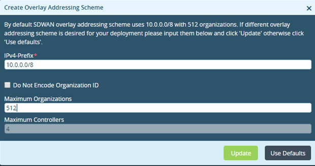
- Click Deploy to activate the Controller node. The Create Overlay Addressing Scheme window opens.
- Enter the IPv4 prefix for the overlay network and the maximum number of organizations that the network allows, and then click Update.
- Select Infrastructure > Controllers in the horizontal menu bar. The Configure Basic screen displays.
Note:If you do not configure an IPv4 prefix before you deploy the first Controller node in the network, the default overlay prefix, 10.0.0.0/8, is used. After you deploy the first Controller node, you cannot modify or select the overlay prefix. Therefore, if you want to use a different overlay prefix, configure and deploy it at this point in the installation setup, after you install the Director node. For more information, see Configure the Overlay Addressing Scheme.
- For Releases 21.2 and earlier:
- Select Infrastructure > Controllers in the left menu bar.

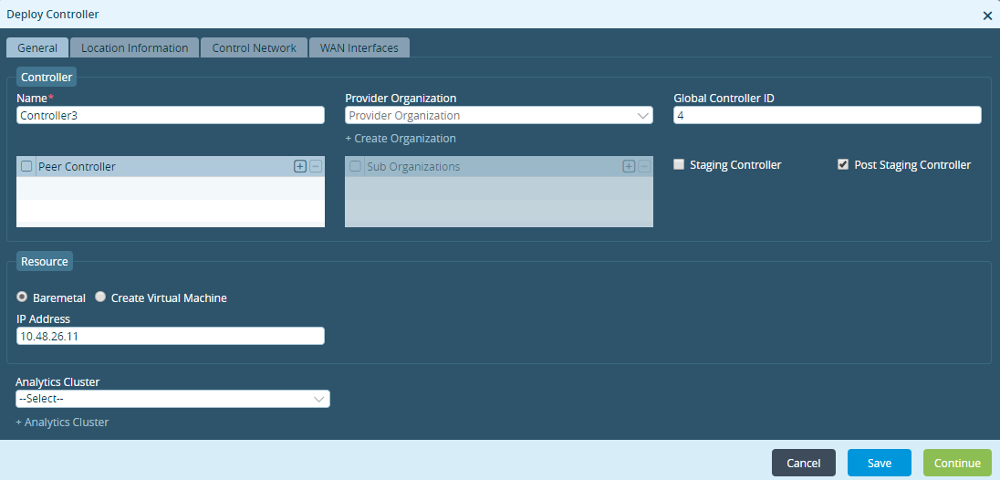
- Click the Add icon. The Deploy Controller popup window displays.
- In the General tab:
- Enter the name of the Controller node in the Name field (required).
- Select a provider organization. If you have not previously created provider organizations, the list is empty. To create a new provider organization, click + Create Organization. For more information, see Create Provider Organizations.
- Click Bare Metal.
- Enter the IP address of the Controller node's eth0 interface.
- Click Continue.
- In the Location Information tab:
- Enter the physical address of the Controller node.
- Click Get Coordinates to automatically populate the latitude and longitude fields based on the Controller node's physical address.
- Click Continue.

- In the Control Network tab, enter information about the control network interface, which is the interface that connects the Controller node to the Director node and allows communication between the Director node and the VOS branch devices. Click Continue.

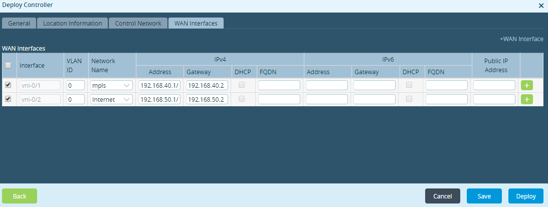
- In the WAN Interfaces tab, enter information about the interfaces that the Controller node uses to communicate with SD-WAN branches. When the Controller node is in a data center behind a NAT device, use a public IP address. For the Controller node’s WAN IP address, it is recommended that you have a one-to-one NAT mapping between private and public addresses if the Controller node's WAN interface is behind a NAT. You must configure the NAT public IP address when you add a WAN interface to the Controller node.
- Click the
 Deploy button to activate the Controller node. The Create Overlay Addressing Scheme window opens.
 - Enter the IPv4 prefix for the overlay network and the maximum number of organizations that the network allows, and then click Update.
- Select Infrastructure > Controllers in the left menu bar.
Note: If you do not configure an IPv4 prefix before you deploy the first Controller node in the network, the default overlay prefix, 10.0.0.0/8, is used. After you deploy the first Controller node, you cannot modify or select the overlay prefix. Therefore, if you want to use a different overlay prefix, configure and deploy it at this point in the installation setup, after you install the Director node. For more information, see Configure the Overlay Addressing Scheme.
Supported Software Information
Releases 20.2 and later support all content described in this article, except:
- Release 21.1.1 adds support for the secure option with the cluster installation script.
- For Releases 21.2 and later, the vsh stop command replaces the service vnms command.
- Release 22.1.1 adds support for Analytics aggregator nodes. You can select the active or standby Director node when configuring a static route.
- Release 22.1.4 adds the zookeeper_node and ntp_servers fields to the clustersetup.conf file. File clustersetup_def.conf is added.
- Release 23.1.1 adds support for setting up an Analytics cluster from the Director UI.
Additional Information
Configure AAA
Configure Analytics Aggregator Nodes
Configure Log Collectors and Log Exporter Rules
Configure the Overlay Addressing Scheme
Configure Systemwide Functions
Director GUI Overview
Expand Disk Storage for Analytics Nodes
Expand Disk Storage for Director Nodes
Features and Capabilities
Hardware and Software Requirements for Headend
Upgrade Software on Headend and Branch