Configure Systemwide Functions
![]() For supported software information, click here.
For supported software information, click here.
This article describes how to configure a number of systemwide functions on Director nodes.
Configure High Availability in Releases 22.1.4 and Earlier
High availability (HA) provides a fallback option in case the active Director node goes down. HA ensures a seamless bringup of the standby Director node, thus allowing network services to continue with no disruptions.
The Director node supports the following flows for HA:
- Netconf
- Fault module supports UDP and TCP channels
For a UDP channel, syslog messages are sent to the active and standby Director nodes, but only the active node processes the alarms. You configure a remote collector for the active-standby pair. For a TCP channel, only the active Director node accepts a connection, and you configure a log collector group for the active-standby pair. Data between the active and standby Director nodes is synchronized by Postgres replication.
Any settings that you configure on the active Director node automatically extend to the standby Director node. The standby node cannot perform any action until it activates.
View HA Settings
For Releases 22.1.1 and later.
To view the Director HA settings:
- In Director view, select the Administration tab in the top menu bar.
- Select System > High Availability in the left menu bar. The following screen displays.

The High Availability pane displays the following read-only information about the HA components:

Configure HA for Director Nodes in Releases 21.2.1 and Earlier
For Releases 21.2.1 and earlier.
- Install Versa Director on two hosts (virtual machines, or VMs).
- Log in to one of the Director nodes.
- In Director view, select the Administration tab in the top menu bar.
- Select System > High Availability in the left menu bar.

- In the High Availability pane, click the
 Edit icon. In the High Availability popup window, enter information for the following fields.
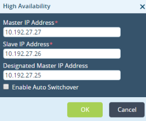
Field Description Master IP Address Enter the IP address of the active Director node. Slave IP Address Enter the IP address of the standby Director node. Designated Master IP Address Enter the IP address of the designated active Director node. Enable Auto Switchover Click to enable automatic switchover to the backup Director node if the active Director node goes down. - Click OK.
Configure Revertive Behavior
By default, the Director HA implementation is non-revertive, which means that if the designated master is up and running after a recovery, it is not promoted to master. To change the behavior to be revertive, so that the designated master is promoted to active after a recovery, you enable automatic switchover. The designated master is then promoted to active after the automatic switchover timeout value expires.
It is recommended that you not change the HA configuration values in production deployments.
To enable revertive behavior in Releases 22.1.1 and later:
- In the Director view, select the Administration tab in the top menu bar.
- Select System > High Availability in the left menu bar.

- In the High Availability Configuration pane, click the
 Edit icon. In the Edit Configure HA popup window, enter information for the following fields.
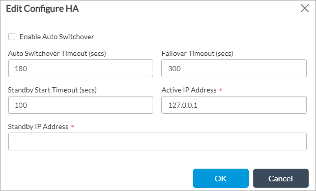
Field Description Enable Auto Switchover Click to enable the designated active Director node to promote itself to the active state after a recovery. Auto Switchover Timeout Enter the timeout period, in seconds, before the designated active Director node promotes itself to the active state after a recovery.
Range: 180 through 3600 seconds (60 minutes)
Default: 180 seconds (3 minutes)Failover Timeout Enter the timeout period, in seconds, before the standby Director node can promote itself to be the active Director node.
Range: 180 through 3600 seconds (60 minutes)
Default: 300 seconds (5 minutes)Standby Start Timeout
Enter how long, in seconds, a non-designated standby node waits before it promotes itself to the active state.
Range: 0 through 3600 seconds (60 minutes)
Default: 100 secondsActive IP Address
Enter the IP address of the active Director node. This field is disabled if HA is enabled for the Director node. Standby IP Address
Enter the IP address of the standby Director node. This field is disabled if HA is enabled for the Director node. - Click OK.
To enable revertive behavior in Releases 21.2 and earlier:
- In the Director view, select the Administration tab in the top menu bar.
- Select System > High Availability in the left menu bar.
- In the HA Configuration pane, click the
Edit icon. In the Edit Configure HA popup window, enter information for the following fields.

Field Description Enable Auto Switchover Select to enable the designated active Director node to promote itself to the active state after a recovery. Auto Switchover Timeout Enter the timeout period, in seconds, before the designated active Director node promotes itself to the active state after a recovery.
Range: 0 through 3600 seconds (60 minutes)
Default: 120 seconds (2 minutes)Failover Timeout Enter the timeout period, in seconds, before the standby Director node can promote itself to be the active Director node.
Range: 0 through 3600 seconds (60 minutes)
Default: 300 seconds (5 minutes)Standby Start Timeout
Enter how long, in seconds, a non-designated standby node waits before it promotes itself to the active state.
Range: 0 through 3600 seconds (60 minutes)
Default: 100 secondsActive IP Address
Enter the IP address of the active Director node. This field is disabled if HA is enabled for the Director node. Standby IP Address
Enter the IP address of the standby Director node. This field is disabled if HA is enabled for the Director node. - Click OK.
Configure HA Failover
You can manually cause the Director active node to fail over. Doing this causes the active Director node to become the standby, and the standby node to become the active Director node.
For Release 22.1.1 and later, click Failover in the High Availability Configuration pane.

For 21.2 and earlier, click Failover in the High Availability pane.

For automatic failover, if the active Director node is down because of network issues or if the vnms process has stopped, the standby Director node checks the status of the active node for a maximum of 15 minutes (checking at the default interval of 300 seconds for a maximum of three times) before assuming the role as the active Director node. This behavior is not specific to the SSL certificate installation process.
In Releases 22.1.1 and later, to configure the failover timeout,click the ![]() Edit icon in the High Availability pane, enter a value in the Failover Timeout field, and then click OK.
Edit icon in the High Availability pane, enter a value in the Failover Timeout field, and then click OK.
In Releases 21.2 and earlier, you configure the failover timeout using REST API calls or the following Director CLI commands.
To display the failover timeout, issue the following CLI command:
Administrator@VOAEHA2> show vnmsha ha-config failover-timeout
failover-timeout 300;
To set the failover timeout, issue the following CLI command:
Administrator @VOAEHA2% set vnmsha ha-config failover-timeout seconds
For example, to set the failover timeout to 60 seconds:
Administrator @VOAEHA2% set vnmsha ha-config failover-timeout 60
Administrator @VOAEHA2% commit
Delete the HA Configuration
For Releases 22.1.1 and later.
To reconfigure the Director nodes in an HA implementation, you can delete the HA configuration.
To delete the HA configuration on a Director node on which HA is enabled:
- In the High Availability Configuration section, click Disable HA.
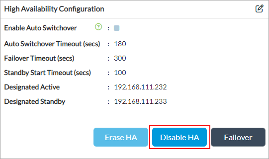
- Click Erase HA.
- To reconfigure the HA node, click the Edit icon. The Edit Configure HA screen displays. For more information, see Configure Revertive Behavior above.
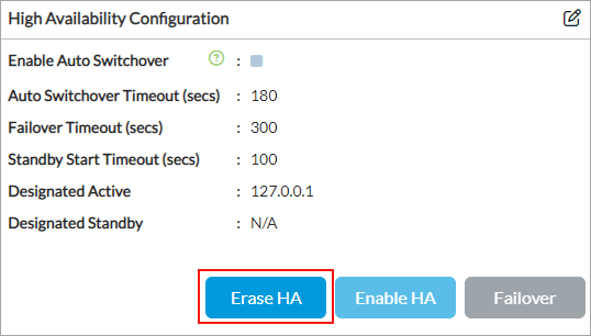
To remove the HA configuration on a Director node on which HA is not enabled, click Erase HA in the High Availability Configuration pane.
Configure OAuth
The Versa Director UI and Versa Analytics use the Open Authorization (OAuth) login protocol to communicate with the Director node. OAuth has two mechanisms for logging in:
- Client registration—The Director administrator registers the application client and shares the client ID and client secret with the user, who uses the information to access the application and refresh the tokens.
- Token registration—An administrator creates a client registration token and shares with the user, who uses the token to invoke a REST API call. As a result, the application self-registers and generates the client ID and secret ID to access the application and refresh the tokens.
This section describes how to register clients and tokens.
Register Clients
- In Director view, select the Administration tab in the top menu bar.
- Select System > Authorization > Clients in the left menu bar.

- Click the
 Add icon. In the Add Client popup window, enter information for the following fields.

Field Description Name (Required) Enter a name for the client. Description (Required) Enter a text description for the client. Expiry (Group of Fields) - Client Expires On
Enter the expiration date and time for the client ID. - Client Secret Expires On
Enter the expiration date and time for the secret ID. Grant Types (Group of Fields) - Password
Click to issue a password for access. - Refresh Token
Click to issue a refresh token to generate a new token for access. Disable Click to deactivate the client after you commit the configuration. Access (Group of Fields) - Maximum Tokens per User (Required)
Enter the maximum number of tokens to allocate to each user.
Range: 0 through 9223372036854775807
Default: 1
- Token Validity (Required)
Enter how long the token is valid, in seconds.
Range: 0 through 9223372036854775807 seconds
Default: 900 seconds
- Refresh Token Validity (Required)
Enter how long the refresh token is valid, in seconds. When a token expires, it has to be refreshed using a refresh token, which generates a new access token for the client.
Range: 0 through 9223372036854775807 seconds
Default: 86400 seconds
- Click OK.
Configure an External OAuth Server
- In Administration view, go to System > OAuth > External OAuth Server in the left menu bar.
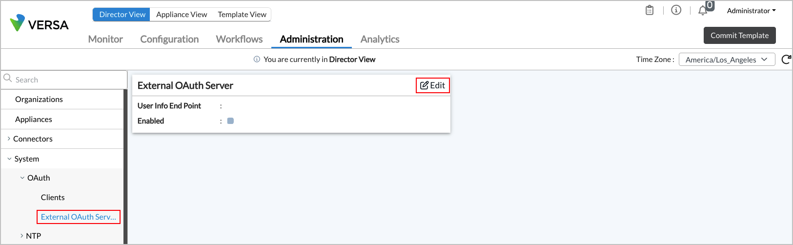
- Click the Edit icon in the External OAuth Server panel.

- In the Edit Extermal OAuth Server screen, enter information for the following fields.
Field Description User Info End Point Enabled Click to enable the user end point. User Attributes (Group of Fields) Enter the user's email address. - Organization
Enter the user's organization. - Roles
Enter the user's role. - Click OK.
- Select the Credential tab, and enter information for the following fields.
Field Description URL (Group of Fields) - Client URL
Enter the URL to invoke. - Redirect URL
Enter the URL to which to redirect the user. Address (Group of Fields) Configure how to grant access authorization to the OAuth client. - Any
Click to grant access to all IP addresses. - Source Address
Click to grant access only to specific IP addresses. Click the  Add icon to add the addresses in the table.
Grant Types (Group of Fields) Select one or more types of access to grant to an application. - Client Credentials
Click to issue a client ID and secret ID. - Password
Click to issue a password for access. - Refresh Token
Click to issue a refresh token to generate a new token for access. - Select the Expiry tab, and enter information for the following fields.

Field Description Client Expires On Enter the expiration date and time for the client ID. Client Secret Expires On Enter the expiration date and time for the secret ID. - Select the Contacts tab, and enter information for the following fields.
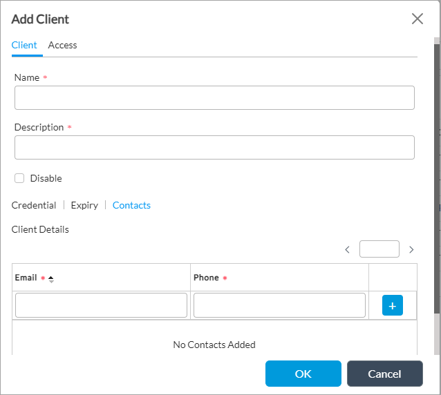
Field Description Email (Required) Enter the email address for the client contact. Phone (Required) Enter the telephone number for the client contact.  Add icon
Click the  Add icon to add the contact information.
- Click OK.
View System Uptime
In Director view, select the Monitor tab in the top menu bar to view the system uptime and application uptime in the monitor dashboard.

View System Resources
In Director view, select the Monitor tab in the top menu bar to view the system details usage, including memory usage, CPU load, and disk usage in the monitor dashboard.

Configure an NTP Server
The Network Time Protocol (NTP) synchronizes clock times on the computers in a network. NTP synchronizes computer clock times to within a few milliseconds of Coordinated Universal Time (UTC). To use NTP, you configure an NTP server in a network.
In Releases 22.1.4 and later, you can configure authentication for NTP by creating an authentication key, using either MD5 or SHA1.
In Releases 23.1.1 and later, NTP uses Chrony as the underlying time synchronization service instead of the legacy ntpd daemon. See Chrony Time Synchronization Service, below.
Add an NTP Server
- In Director view, select the Administration tab in the top menu bar.
- Select System > NTP > Server in the left menu bar.

- Click the Add icon. In the Create NTP Server popup window, enter information for the following fields.
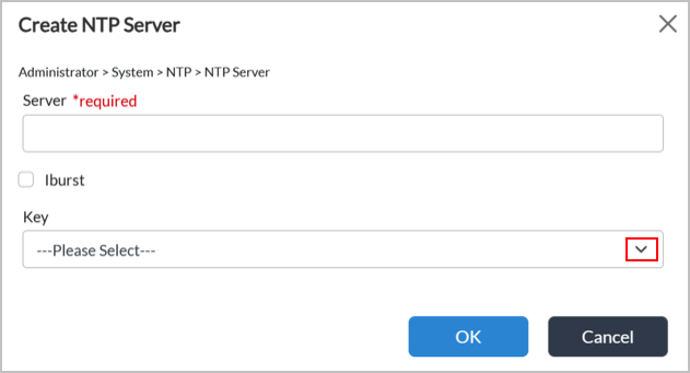
Field Description Server (Required) Enter a name for the server. Iburst Click to enable iburst on the server. Iburst improves the time required for initial synchronization by sending a burst of 8 packets (instead of 1) when the NTP server is unreachable.
(For Release 23.1.1 and later.) When iburst is enabled, Chrony sends a burst of 4 requests (instead of 1) during the first poll to each server, which allows the clock to synchronize significantly faster after a restart or initial configuration. Without iburst, initial synchronization can take several minutes; with it, initial synchronization typically completes within seconds. It is recommended to always keep iburst enabled.
Key (For Release 22.1.4 and later.) Select an authentication key. For more information, see Create an NTP Authentication Key, below. - Click OK.
Create an NTP Key
For Releases 22.1.4 and later.
Note: NTP keys are supported only for private NTP servers.
To create an NTP key:
- In Director view, select the Administration tab in the top menu bar.
- Select System > NTP > NTP Key in the left menu bar.

- Click the Add icon. In the Add Create NTP Key popup window, enter information for the following fields.
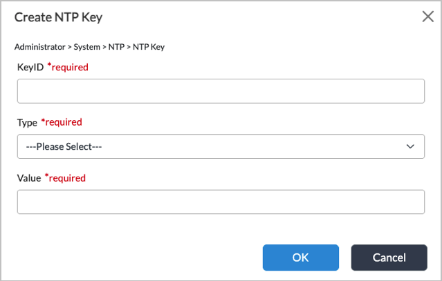
Field Description Key ID (Required) Enter an ID number for the NTP key.
Range: 1 through 65535.
Default: None
Type (Required) Select an authentication type:
- md5
- sha1
- sha256
- sha384
- sha512
Value (Required) Enter a password for the NTP key. - Click OK.
Chrony Time Synchronization Service
For Releases 23.1.1 and later.
Chrony is the underlying time synchronization service for NTP. Chrony replaces the ntpd daemon, and provides improved accuracy, faster convergence, and support for SHA-2 authentication algorithms. NTP remains fully interoperable with remote NTP servers using the standard NTP protocol, and no changes are required on the remote server side.
Chrony Commands
Use the following commands to displays information about Chrony and to force an immediate clock correction instead of waiting for gradual slewing.
- chronyc sources -v—Shows Chrony sources and source states:
- *—Indicates the source is currently synced.
- ?—Indicates the source is unreachable.

- chronyc tracking—Shows the system clock's current synchronization status.
[Administrator@Dir76: ~] $ chronyc tracking
Reference ID : D8EF2308 (time3.google.com)
Stratum : 2
Ref time (UTC) : Wed Mar 18 15:06:06 2026
System time : 0.000245407 seconds fast of NTP time
Last offset : +0.000654517 seconds
RMS offset : 0.001772926 seconds
Frequency : 24.344 ppm slow
Residual freq : -2.255 ppm
Skew : 0.423 ppm
Root delay : 0.078772560 seconds
Root dispersion : 0.000182643 seconds
Update interval : 65.1 seconds
Leap status : Normal
- chronyc activity—Shows how many NTP sources are currently online or offline.
[Administrator@Dir76: ~] $ chronyc activity
200 OK
1 sources online
0 sources offline
0 sources doing burst (return to online)
0 sources doing burst (return to offline)
0 sources with unknown address
- chronyc ntpdata—Shows detailed NTP protocol-level information for the current source. This is the most comprehensive diagnostic command and requires root privileges. When using key-based authentication, you can check the Authenticated field to verify whether the server is responding with authenticated packets.
[Administrator@SDWAN-VOAE1: ~] $ sudo chronyc ntpdata
Remote address : 10.195.57.218 (0AC339DA)
Remote port: 123
Local address : 10.195.57.215 (0AC339D7)
Leap status: Normal
Version: 4
Mode: Server
Stratum: 3
Poll interval : 6 (64 seconds)
Precision: -23 (0.000000119 seconds)
Root delay: 0.144302 seconds
Root dispersion : 0.017990 seconds
Reference ID: B97DBE38 ()
Reference time : Mon Mar 09 11:53:04 2026
Offset: -0.000272422 seconds
Peer delay: 0.000440555 seconds
Peer dispersion : 0.000000179 seconds
Response time : 0.000151378 seconds
Jitter asymmetry: +0.00
NTP tests: 111 111 1111
Interleaved: No
Authenticated : Yes
TX timestamping : Kernel
RX timestamping : Kernel
Total TX: 5
Total RX: 5
Total valid RX : 5
Key chronyc ntpdata fields:
| Field | Description |
|---|---|
| Remote address / port | IP address and port (UDP 123) of the NTP server being queried. |
| Stratum | The server's distance from a reference clock. If the value is 1, the server is directly attached to a reference clock. The value increases with the number of hops from a reference clock. |
| Poll interval | How frequently (in seconds) the client polls this server. Chrony adjusts this interval dynamically. |
| Root delay | The total round-trip delay to the primary reference clock through the entire chain of NTP servers. |
| Root dispersion | Cumulative clock error estimate across the entire chain to the reference clock. |
| Offset | The measured time difference between the local clock and the server. A positive value means the local clock is ahead. |
| Peer delay | The round-trip network delay between this client and the NTP server. |
| NTP tests |
Results of NTP protocol validation tests:
|
| Authenticated | Shows whether the server's responses are authenticated using a shared key. If the value is Yes, key-based authentication is active. |
| Total TX / RX / Valid RX | Count of packets sent, received, and successfully validated. A mismatch between RX and Valid RX may indicate authentication or packet integrity problems. |
- chronyc makestep—Forces an immediate clock correction instead of waiting for gradual slewing. This command is useful after initial setup or when the clock is significantly off.
[Administrator@Dir76: ~] $ sudo chronyc makestep
Troubleshooting Chrony
Use the following commands to troubleshoot Chrony.
| Symptom | Command | Resolution |
|---|---|---|
| Source is unreachable |
chronyc sources -v
|
Check the Source state field in the command output. The value "?" indicates the source is unreachable. Verify the server hostname/IP address, check network connectivity and firewall (UDP port 123). |
| Clock not syncing |
chronyc tracking |
Ensure that at least one source is reachable. Run sudo chronyc makestep to force a sync. |
| Authentication failure |
chronyc ntpdata |
Check the Authenticated field. Verify that the key ID, algorithm, and value match on both client and server. |
| Service not running |
sudo systemctl status chrony |
Check logs with journalctl -u chrony and restart them with sudo systemctl restart chrony. |
Configure an NTP Server Manually
Use manual configuration only when it is not possible to configure NTP servers from the UI.
Add NTP Servers
- Edit the servers file:
[Administrator@Dir76: ~] $ sudo vim /etc/chrony/chrony.servers
- Add servers in the following format (always use iburst for faster initial sync):
server time.google.com iburst
server <server_name> iburst
- Configure a server with key-based authentication:
server 10.195.9.71 iburst key 1 version 4
server <server_name> iburst key version 4
Create NTP Keys
- Edit the keys file:
[Administrator@Dir76: ~] $ sudo vim /etc/chrony/chrony.keys
- Add keys in the following format. The available key algorithms are MD5, SHA1, SHA256, SHA384, and SHA512:
<key_id> <ALGORITHM> <key_value>
For example:
1 SHA256 test@123
Apply Changes
- After modifying chrony.servers or chrony.keys , restart the Chrony service:
[Administrator@Dir76: ~] $ sudo systemctl restart chrony
- Verify the service status:
[Administrator@Dir76: ~] $ sudo systemctl status chrony
The expected output (active and running) is as follows:
chrony.service - chrony, an NTP client/server
Loaded: loaded (/lib/systemd/system/chrony.service; enabled; vendor preset: enabled)
Active: active (running) since Mon 2026-03-09 03:26:12 UTC; 5s ago
Docs: man:chronyd(8)
man:chronyc(1)
man:chrony.conf(5)
Main PID: 352 (chronyd)
Configure the Primary Node as the NTP Server for the Cluster
Use this procedure when cluster nodes must synchronize to the primary node.
- On the primary node:
- Edit the Chrony configuration file.
admin@direc-213:~$ sudo vim /etc/chrony/chrony.conf
- Add the secondary and arbiter node IP addresses to the allow list, and ensure that the local stratum line is present and uncommented (both sections already exist in the file; uncomment or add lines as needed). The allow directives permit those hosts to query this host as an NTP server. The local stratum 10 directive allows Chrony to serve time to allowed clients using the local undisciplined clock at the specified stratum (adjust the example IP addresses to match your deployment).
# Allow NTP client access from local network.
#allow 192.168.0.0/16
allow 10.195.8.214 # secondary node IP
allow 10.195.8.215 # arbiter node IP
# Serve time even if not synchronized to a time source.
local stratum 10
- Edit the Chrony configuration file.
- On the secondary and arbiter nodes:
- Edit the servers file so these nodes use the primary as their NTP source.
admin@direc-214:~$ sudo vim /etc/chrony/chrony.servers
- Edit the servers file so these nodes use the primary as their NTP source.
- Configure the primary node as the NTP server.
server 10.195.8.213 iburst
server <primary_node_ip> iburst
- Apply Changes. After making the necessary changes on all the nodes, restart the Chrony service on all of them (see the Apply Changes section above):
sudo systemctl restart chrony
- Verify the changes:
- On the primary node, run the following command:
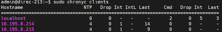
admin@direc-213:~$ sudo chronyc clients
The output must enlist the secondary and arbiter node IP addresses. Sample output:
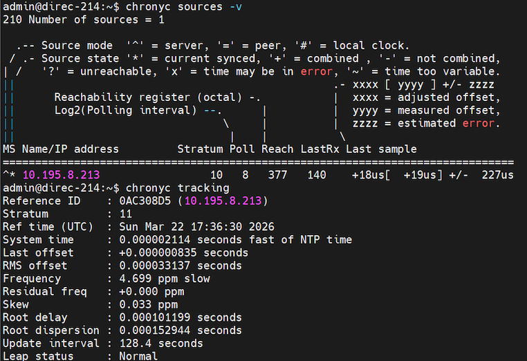
- On the secondary and arbiter nodes, run the following commands:
chronyc sources -v
chronyc tracking
Both commands should list the primary node's IP address as the source. Sample output:
- On the primary node, run the following command:
Configure Static Routes
Static routes are fixed and do not change, even if the network is changed or reconfigured. They are useful when dynamic routing fails.
To configure a static route:
- In the Director view, select the Administration tab in the top menu bar.
- Select System > Static Routes in the left menu bar.

- For Releases 22.1.1 and later, when a standby node is available, you can add static routes to the active or standby Director node:

- Click the Add icon. In the Create Static Route popup window, enter information for the following fields.
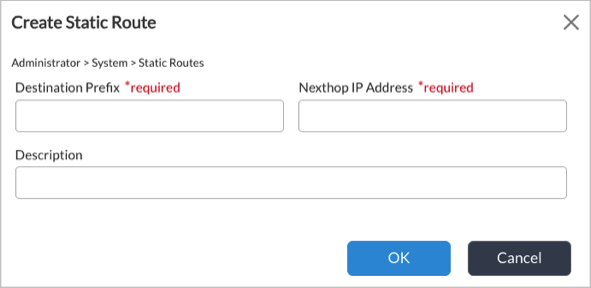
Field Description Destination Prefix Enter the destination IP address of the static route. Next-Hop IP Address (For Releases 21.2 and earlier.) Enter the IP address of the next-hop interface to reach the destination. Description (For Releases 22.1.1 and later.) Enter a text description for the static route. - Click OK.
Configure a DNS Server
A Domain Name System (DNS) server maintains a directory of domain names and translates them to Internet Protocol (IP) addresses.
To configure a DNS server:
- In Director view, select the Administration tab in the top menu bar.
- Select System > DNS in the left menu bar.

- Click the
 Edit icon. In the Edit DNS popup window, enter information for the following fields.

Field Description Name Servers Click the  Add icon, and enter the IP address of the DNS server.
Search Domain Click the Add icon, and enter the IP address that the DNS service uses to resolve hostnames that are not fully qualified.Local Domain Enter the IP address of the local domain. - Click OK.
Verify the Director System License Status
For Releases 21.2 and earlier.
To verify the license status of a Director node:
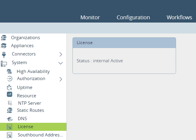
- In Director view, select the Administration tab in the top menu bar.
- Select System > License in the left menu bar.
View the Director License and Upload the License Key
For Releases 22.1.1 and later.
- In Director view, select the Administration tab in the top menu bar.
- Select System > License in the left menu bar.
- Select the active or standby Director node to view in the Node ID field. The License screen displays the information about the Director license. For example:

- Click the
 Edit icon to upload a new license key. The license key file must be in .key format. The Upload popup window displays.

- Click Choose File and then select the license key file from your device.
- Click the
 Download icon to download the node ID file.
 - Click Upload.
Configure Subjugate Addresses
Subjugation allows a Director node to control selected Versa Operating SystemTM (VOSTM) devices exclusively so that all network communication between VOS devices can happen only through that Director node. One reason to subjugate VOS devices to a particular Director node is to streamline the management of branches and network services.
To enable subjugation:
- In Director view, select the Administration tab in the top menu bar.
- Select System > Settings in the left menu bar. In Releases 22.1.1 and earlier, select System > Southbound Addresses in the left menu bar.

- In the Southbound IP Addresses pane, click theEdit icon to add IP addresses.

- Enter an IP address, then click the
 Add icon.
 - Click OK.
Enable the Secure Upload
To enable signature verification for secure upload, see Configure Signature Verification for Software Package Uploads.
Configure Stolen Branch Settings
To edit the stolen branch settings on a Director node:
- In Director view, select the Administration tab in the top menu bar.
- Select System > Settings in the left menu bar. In Release 22.1.1, select System > Settings > Stolen Branch Settings in the left menu bar.
- In the Stolen Branch pane, click the
 Edit icon.

- In the Edit Stolen Branch Setting popup window, enter information for the following fields.
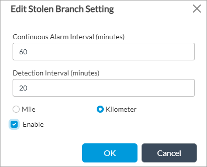
Field Description Continuous Alarm Interval Enter how often, in minutes, to send a continuous alarm when theft of a device is suspected.
Default: 60 minutes
Detection Interval Enter how often, in minutes, to check for detect suspected stolen devices.
Default: 20 minutesDistance Unit - Miles
Click to use miles for distance-based detection. This is the default.
- Kilometers
Click to use kilometersfor distance-based detection. Enable Click to enable antitheft detection.
- Click OK.
Configure the Timezone
To configure the timezone on a Director node:
- In the Director view, select the Administration tab in the top menu bar.
- Select System > Settings in the left menu bar. In Releases 22.1.1 and earlier, select System > Time Zone in the left menu bar.

- In the Timezone pane, click theEdit icon.
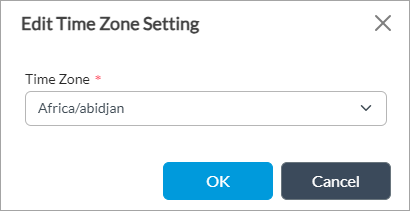
- In the Edit Time Zone Setting popup window, select the timezone in the Time Zone field.
- Click OK.
Configure Proxy Settings
To configure proxy settings for HTTP or HTTPS:
- In the Director view, select the Administration tab in the top menu bar.
- Select System > Settings in the left menu bar. In Releases 22.1.1 and earlier, select System > Proxy Setting in the left menu bar.

- In the Proxy Setting pane, click the Edit icon.
- In the Edit Proxy Settings popup window, enter information for the following fields.
Note: For Releases 22.1.1 and later, you must add the HA IP addresses of both the active and standby Directors under Exceptions below.
Note: If you configure Director to use a proxy for operating system security package (OS SPacks) and security package (SPack) updates, you must add an exception for the Versa Messaging Service (VMS) IP address that Director uses to communicates with it, typically the northbound IP address of VMS.

Field Description Enabled Click to enable proxy settings. HTTP Host Enter the HTTP hostname or IP address of the proxy. HTTP Port Enter the HTTP port number of the proxy. HTTPS Host Enter the HTTPS hostname or IP address of the proxy. HTTPS Port Enter the HTTPS port number of the proxy. Username Enter the login name to access the proxy. Password Enter the password to access the proxy. Exceptions Click the
Add icon to add the hostname or IP address of exceptions for the proxy. Note: For Releases 22.1.1 and later, you must add the HA IP addresses of both the active and standby Directors. For example:

- Click OK.
Configure the Bash Shell
To configure the Bash shell:
- In the Director view, select the Administration tab in the top menu bar.
- Select System > Settings in the left menu bar.

- In the Bash Config pane, click the Edit icon.
- In the Edit Bash Config popup window, enter information for the following fields.
Note: The "Retries before Lockout" field is not a configurable parameter. As a result, it does not appear in the Edit Bash Config screen shown below.
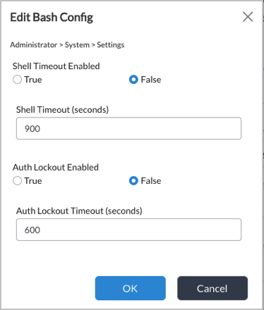
Field Description Shell Timeout Enabled Select True or False to enable or disable the shell timeout. The default is False (shell timeout is disabled).
Shell timeout is a Versa Director security feature that automatically terminates idle bash/SSH shell sessions after a configured period of inactivity. If a session remains idle (no user input) for the configured (Shell Timeout) duration, the shell is automatically terminated.
Shell Timeout (in sec) If you enabled the shell timeout option, enter the length of time until the shell times out, in seconds.
Default: 900 seconds
Auth Lockout Enabled Select True or False to enable or disable authorization lockout. The default is False (authorization timeout is disabled).
Auth Lockout is a Versa Director security feature that protects against brute-force SSH authentication attacks by locking out user accounts after a configured number (Retries before Lockout) of consecutive failed login attempts .
When enabled, the Director configures Pluggable Authentication Module (PAM)-level lockout on the host system. Once a user exceeds the allowed number of failed authentication retries, their account is locked for a configurable duration, preventing any further login attempts until the lockout period expires. After the lockout timeout expires, the account is automatically unlocked.Auth Lockout Timeout (in sec) If you enabled the authorization lockout, enter the length of time until the authorization locks out, in seconds.
Default: 600 seconds
- Click OK.
Configure Local Organizations
To configure a local organization and associate it with a network name and VLAN IP address:
- In Director view, select the Administration tab in the top menu bar.
- Select Connectors > Local > Organization in the left menu bar.

- Click the Add icon. In the Add Organization popup window, enter information for the following fields.

Field Description Name Enter a name for the organization. Description Enter a text description for the organization.
- Select the Networks tab, and enter information for the following fields.
Field Description Networks (Group of Fields) Name Name of the network. VLAN
Enter the VLAN IP address. IPv4 Allocation Mode
Select how to allocate IPv4 addresses: - DHCP
- Manual
IPv6 Allocation Mode
Select how to allocate IPv6 addresses: - DHCP
- Manual
- Select the Resources tab, and enter information for the following fields.

Field Description Resource Pool (Group of Fields) Server Name
Enter the names of one or more servers. IP Address/Host Name
Enter the IP address or host name of the server. Click the  Add icon to add an additional server.
 - Click OK.
Configure AMQP Connectors
The Advanced Message Queuing Protocol (AMQP) is an open standard application layer protocol for messages. The key features of AMQP are message orientation, queuing, routing, reliability, and security. The AMQP connector defines which credentials to use when connecting, and it defines all the common properties used by the inbound and outbound endpoints that use the connector.
To configure an AMQP connector:
- In Director view, select the Administration tab in the top menu bar.
- Select Connectors > AMQP in the left menu bar.

- Click the Add icon. In the Add AMQP Connector popup window, enter information for the following fields.
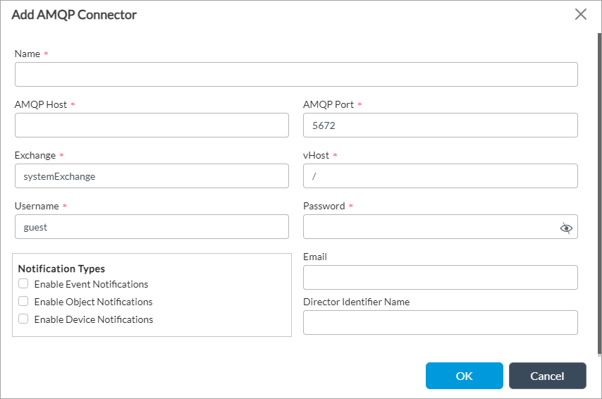
Field Description Name Enter a name for the AMQP connector. AMQP Host Enter the IP address of the AMQP connector. AMQP Port Enter the port number that the AMQP connector uses. Exchange Enter the address of the exchange server. vHost Enter the name of the vHost server. Username Enter the login name to access the server. Password Enter the password to access the server. Notification Types Click to receive notifications. Email Enter the email ID to send AMQP server connectivity notification.
Director Identifier Name Enter a name for the Director identifier.
- Click OK.
Supported Software Information
Releases 20.2 and later support all content described in this article, except:
- In Release 22.1.1:
- High Availability section in the High Availability screen is view only. Move Designated Active and Designated Standby fields to the High Availability Configuration section. Add ability to delete an HA configuration.
- You can select the active or standby Director node to add static routes when you select Administration > Static Routes. Remove Next-Hop IP Address and Next-Hop Interface fields from the Add Static Route screen.
- The License screen displays additional details such as mode, days elapsed, and days remaining. You can download the node ID binary file and edit the license to upload license key.
- In Release 22.1.2, add System > Settings in the left menu bar and move System > Southbound IP Addresses, System > Stolen Branch Setting, System > Secure Upload Setting, System > Timezone Setting, and System > Proxy Setting items in the left menu bar to System > Settings.
- In Release 22.1.4, you can configure authentication for NTP by creating an authentication key, using either MD5 or SHA1; you can configure the Bash shell.
- In Releases 22.1.x and later, neutral terms have replaced master, slave, arrived, and died instances in the HA UI. The renamed terms are active, standby, online, and offline; except for "designated master," which will remain in the NCS CLI, REST API responses, as well as other non-UI references.
- Releases 23.1.1 and later add support for the sha256, sha384, and sha512 NTP authentication key types. In addition, NTP now uses Chrony as the underlying time synchronization service instead of the legacy ntpd daemon.
Additional Information
Configure Single Sign-On Using Director
Firewall Requirements