Configure IP Multicast
![]() For supported software information, click here.
For supported software information, click here.
This article describes how to configure IP multicast protocols on Versa Operating SystemTM (VOSTM) devices.
IP Multicast Overview
IP multicast is a suite of protocols for distributing application data from a single source host to many receiver hosts over an IP network in a bandwidth-efficient manner. IP multicast sends data to hosts that have explicitly asked to receive the data. It is typically used by streaming video, online gaming, financial applications, and broadcasting applications.
Multicast routing protocols provide the means for receiver hosts to express interest in a multicast application data flow and for routers to create the paths over which the multicast data travels from the source host to the receiver hosts. Receiver hosts express interest in receiving multicast traffic by sending an internet group management protocol (IGMP) join message. Routers closest to the receiver host receive the join message and begin to form a multicast distribution tree towards the source host. The IP address of the source host is used by multicast routing protocols to determine the direction of the application data flow.
A multicast group consists of receiver hosts that have asked to receive a particular stream of application data. The local multicast router that receives the join requests then sends this group-membership information to all routers in the network. The source host sends one copy of the application data, and routers along the distribution path replicate the data and forward it to the appropriate routers for delivery to the members of the multicast group. Each multicast group is assigned one IP address. All multicast IP addresses are Class D addresses that are in the range of 224.0.0.0 to 239.255.255.255. You cannot create subnetworks for multicast IP addresses.
In the figure below, Hosts A, B, and C have sent IGMP join messages to receive the application data stream from Source A and are now part of Multicast Group 1. Host D has not joined Multicast Group 1, so it does not receive the application data stream.

A number of multicast networking protocols have been developed to enable IP multicast and to make more efficient use of network resources when supporting these types of applications. Versa Networks supports the following multicast protocols:
- Internet Group Management Protocol (IGMP), Version 1, Version 2, and Version 3
- Protocol-Independent Multicast-Sparse Mode (PIM-SM) with neighbors on LAN, WAN, and SD-WAN overlay interfaces, and rendezvous point (RP)
- PIM Static RP
- Bootstrap Router and Candidate RP
- PIM Anycast RP
- Protocol-Independent Multicast-Source Specific Multicast (PIM-SSM)
IGMP
IGMP is a multicast protocol that is used by hosts and local routers on IPv4 networks to establish and manage multicast group memberships. You enable IGMP between a host device and a local multicast router, as shown below.

A host requests membership to a multicast group by sending join requests to any local multicast router. Another router listens for these requests and sends out subscription queries at regular intervals. A single local multicast router is elected to become a querier router that performs general or group-specific queries for each subnet in a network.
IGMPv2 introduced the ability for a host to send a leave message to the multicast routers to indicate that it is leaving the multicast group. IGMPv3 enhanced IGMPv2 by providing support for source-specific multicast and IPv6, through the Multicast Listener Discovery (MLD) protocol. Source-specific multicast allows multicast data from a particular source to reach a particular multicast group.
The Versa IGMP implementation is fully compliant with IGMPv2, as defined by RFC 2236, and IGMPv3, as defined with RFC 4604.
PIM
Protocol-Independent Multicast (PIM) consists of a group of multicast routing protocols that provide one-to-many and many-to-many data distribution over LAN, WAN, and, in the case of Versa Networks, SD-WAN overlay networks. PIM is used between the local and remote multicast routers to create the path between a source and a receiver, as shown below. It is considered protocol independent because it is not dependent on a specific unicast routing protocol to learn routes—it can use any unicast routing protocol in use on the network.

PIM uses the concept of a PIM domain, which is a set of adjacent routers that all implement PIM and are configured to operate within a common boundary.
Releases 22.1.1 and later support VRRP-aware PIM. In a redundant network with virtual routing groups enabled, VRRP-aware PIM provides consistent IP multicast forwarding by allowing PIM to track the VRRP state and to preserve multicast traffic when a failover occurs.
PIM provides several different modes. Of those modes, Versa supports PIM sparse mode (PIM-SM)—including PIM Anycast RP—and PIM source-specific multicast (SSM).
PIM-SM
PIM sparse mode (PIM-SM) sends multicast traffic only after it receives an IGMP join request from a downstream router. It does not assume that there are hosts on the network waiting to receive multicast traffic.
By default, PIM builds unidirectional shared trees that are rooted at a rendezvous point (RP) for each multicast group. An RP is a router that is configured to be the root for a given multicast group whose multicast source is unknown. The RP receives source multicast traffic from the sender and forwards it to the multicast group. The figure below shows that R2 is the RP for Multicast Group 1.

To send to the RP, first-hop routers (FHRs) must encapsulate data in PIM control messages and send them by unicast to the RP. This is done by the source's designated router (DR), which is a router on the source's local network. Discovering the address of an RP for a given multicast group is critical for PIM-SM. PIM-SM uses several techniques to identify the RP to which a multicast group address is mapped: static RP, candidate RP with the bootstrap router (BSR) mechanism, and anycast RP.
If you use static RP, you must manually configure the IP address of the RP on each router in the multicast domain. Static RP provides a simple way to identify RPs in smaller networks that do not have many RPs.
A router becomes the BSR for its PIM domain through a simple election process. You can configure routers to be candidate RPs. All the routers in the domain that are configured to be candidate RPs periodically send their RP candidacy to the BSR. From the candidates, the BSR chooses a set of RPs and announces this set in a bootstrap message that is sent to all routers in the domain.
PIM Anycast RP
PIM anycast RP provides redundancy and fast convergence when an RP within a multicast domain fails. For PIM anycast RP, you configure two or more RPs with the same IP address, which is known as the anycast IP address. The anycast IP address must be reachable through all PIM-enabled routes within the multicast domain, and it is configured as the RP address in all PIM routers for a given group prefix list.
Each RP providing the anycast functionality needs to know about its peer RPs. You provide this information by configuring a routable IP address for each anycast RP peer in each of the anycast RPs.
With anycast RP, a PIM router always connects to its closest RP. As a result, the source and receiver might join two different anycast RP routers. Consequently, it is essential that all the anycast RP peers learn information about the source. There are two standard methods used to exchange the source group information among the anycast RP peers:
- Multicast Source Discovery Protocol (MSDP)
- PIM register packets
Versa uses PIM register packets to exchange source group information. When an anycast RP receives a PIM register packet, the packet is processed locally and forwarded to all anycast RP peers. Each peer then creates a corresponding (S,G) route entry.
PIM-SSM
PIM-SSM builds trees that are rooted in a single source, offering a more secure and scalable model for a limited number of applications (primarily applications that broadcast content). With PIM-SSM, an IP datagram is transmitted from a source address (S) to a destination address (G), and receivers can receive this datagram by subscribing to a channel (S,G). For more information about PIM-SSM, see RFC 3569.
With PIM-SSM, there is no need for shared trees or RP mapping, and no RP is required. By focusing attention on the one-to-many source-specific multicast (SSM) model, you can deploy highly scalable multicast networks for applications that have one source and many receivers. For example, by using PIM-SSM, applications that distribute television-channel information or stock-market information over the internet or over SD-WAN networks can broadcast information to listeners much more quickly and efficiently by selecting which sources to listen to and by managing the data traffic only in one direction. PIM-SSM is also used for VXLAN overlay tunnels within virtualized data center environments.
Multicast Cluster
When you enable multicast in a full-mesh SD-WAN topology, PIM is enabled on all overlay tunnels towards all remote sites. These overlay tunnel interfaces are replicated on all routing-instances and are included as part of the multicast tree. Because PIM bootstrap router (BSR) messages are sent to all interfaces on all routing instances, this design can result in BSR messages flooding the network and can lead to scaling issues. An SD-WAN multicast cluster reduces multicast traffic to avoid these scaling issues.
A multicast cluster is a group of branches and hubs (in hub-and-spoke topologies) that form PIM relationships only among themselves and not with other branches in a PIM domain. Each cluster can have up to 64 members.
For an SD-WAN multicast cluster, you define a group of participating SD-WAN sites that have PIM enabled in the same tenant (defined with a common global-tenant-id) and in the same routing instance (defined by a common global-vrf-id). A site can be part of multiple clusters, each of which is defined by cluster IDs. For example, in a hub-and-spoke topology, the hub needs to enable PIM on overlay tunnels towards the spokes and peer hubs, which can be configured to be two different multicast clusters.
A cluster ID does not need to be unique across tenants or routing instances. Configured cluster IDs, combined with the global-tenant-id and global-vrf-id, are advertised using private routes to remote sites. If there is at least one common cluster ID in the local and remote cluster lists, PIM is enabled on the overlay tunnel towards the remote site.
The following figure shows two branches configured in hub-and-spoke topologies, and the two branches belong to the same tenant organization. Hub1, Spoke1, Spoke2, and Spoke 3 have formed a multicast cluster group, CL1. Hub2, Spoke4, Spoke5, and Spoke6 have formed a second multicast cluster group, CL2. The spokes in CL1 do not know about the spokes in CL2; similarly, the spokes in CL2 do not know about the spokes in CL1. However, Hub1 and Hub2 have formed a PIM membership between them so that they both belong to CL1 and CL2. If Hub1 goes down, the spokes in CL1 can still reach Hub2, and if Hub2 goes down, the spokes in CL2 can still reach Hub1. In this way, the spoke in each cluster can continue to participate in the multicast network even if their directly connected hub is unreachable.

In addition, to avoid excessive control traffic over cost-sensitive links (for example, LTE), you can limit PIM activation towards remote sites based on the remote site’s participation in the multicast protocol. For example, in a full-mesh topology, PIM does not need to be enabled towards a remote site if PIM is not configured on that remote site. The SD-WAN multicast cluster feature addresses these challenges while enabling PIM on overlay tunnel interfaces.
You can use cluster lists to convert a unicast, full-mesh SD-WAN topology to a multicast hub-and-spoke topology to limit the number of replications performed at a given site. In this scenario, it is recommended that you generate the cluster ID as follows:
- Combine the site ID with the hub-level number to generate the local-cluster-id.
- Include the local-cluster-id and the remote-cluster-id of all remote sites to which PIM needs to be enabled on overlay-tunnel interfaces.
RIB for Multicast Reverse-Path Forwarding
In most current networking designs, unicast and multicast traffic use the same network topology. However, there are a number of scenarios in which you might want to separate the network topologies for unicast and multicast traffic, such as:
- To support underlay multicast replication when an MPLS network is available
- To support a higher number of replications (although at branch replication is limited to a specific number)
- To manage traffic flows
The routing information base (RIB) for multicast Reverse-Path Forwarding (MRPF) provides a solution for these types of use cases.
To support packet replication in the network underlay, you configure a paired tunnel virtual interface (TVI) from the MPLS transport VR to the LAN VR. All the routes that are learned in the MPLS transport VR must be advertised to the LAN VR’s multicast RIB. Routes learned over the SD-WAN path are also installed in the multicast RIB. In the multicast RIB, underlay routes are given higher priority over the routes learned over SD-WAN. As a result, PIM join requests use the underlay path instead of the SD-WAN path. If the MPLS path fails, the control plane automatically begins using the routes learned over the SD-WAN path.
Configure PIM
IP multicast is a method for distributing application data from a single source host to many receiver hosts over an IP network in a bandwidth efficient manner. IP multicast sends data to hosts that have explicitly asked to receive the data. It is typically used by streaming video, online gaming, financial, and broadcasting applications.
PIM provides several different modes. Of these modes, Versa Networks supports PIM Sparse Mode (PIM-SM)—including PIM anycast RP—and PIM Source-Specific Multicast (SSM):
- PIM Sparse Mode (PIM-SM) sends multicast traffic only after it receives an IGMP join request from a downstream router. It does not assume that there are hosts on the network waiting to receive multicast traffic.
- PIM anycast RP allows you to configure more than one RP in a multicast network, to provide redundancy and load balancing.
- PIM-SSM builds trees that are rooted in a single source, offering a more secure and scalable model for a limited number of applications (primarily applications that broadcast content).
Note: In the notation PIM (*,G), G is the multicast group, and the asterisk (*) means any source sending to the multicast group G.
To configure PIM:
- In Director view:
- Select the Administration tab in the top menu bar.
- Select Appliances in the left menu bar.
- Select an appliance in the main pane. The view changes to Appliance view.
- Select the Configuration tab in the top menu bar.
- Select Networking > Virtual Routers in the left menu bar. The currently configured virtual routers display in the main pane.
- Click the
 Add icon. The Configure Virtual Router popup window displays with the Virtual Router Details tab selected by default.

- In the Instance Name field, enter a name for the new virtual router.
- Select the PIM tab in the horizontal menu bar. The main PIM screen displays.

- Click the
 Add icon. In the Add PIM Instance screen, enter information for the following fields. Mandatory fields are indicated with a red asterisk..

Field Description Instance ID Enter an instance identifier to use for PIM. Note that for a given tenant, PIM and IGMP use the same instance ID. Assert Timeout Enter the time duration after which the multicast routing devices enter a PIM assert message cycle.
Range: 5 through 210 secondsJoin Prune Timeout Enter the time duration after which the join state is removed if the join state is not refreshed within that time duration. The router sends periodic join or prune messages to refresh the state.
Range: 210 through 420 secondsOverride Interval Enter the maximum time that a router or switch waits before sending a hoin message to override another device's prune message.
Range: 500 through 6000 millisecondsPropagation Delay Enter how long, in milliseconds, the routing device waits to detect whether a join message is currently being suppressed by another routing device.
Range: 250 through 2000
Group State Limit (For Releases 23.1.1 and later.) Enter the maximum number of multicast groups for which non-interface specific (*,G) and/or (S,G) states are stored.
Range: 1 through 4294967295
Group State Threshold (For Releases 23.1.1 and later.) Enter the threshold to generate an alarm for a number of multicast groups for which non-interface specific (*,G) and/or (S,G) states are stored.
Range: 1 through 4294967295
Source Group State Limit (For Releases 23.1.1 and later.) Enter the maximum number of source and group pairs for which non-interface specific (S,G) states are stored.
Range: 1 through 4294967295
Source Group State Threshold (For Releases 23.1.1 and later.) Enter the threshold to generate an alarm for number of source and group pairs for which non-interface specific (S,G) states are stored. Register Message Filter (For Releases 23.1.1 and later.) Select the filters for register messages that specify the source IP address of the PIM nodes and the multicast group IP addresses (specified as destination IP address) in the extended access list.
Register Send Rate Limit (For Releases 23.1.1 and later.) Enter the maximum number of PIM register messages that a DR sends for a source and group.
Range: 1 through 65535
Register Rate Limit (For Releases 23.1.1 and later.) Enter the maximum number of PIM register messages that can be received on a RP per second for IPv4 or IPv6 version.
Range: 1 through 65535
SPT Threshold Rate Select the threshold value to trigger switchover from the rendezvous-point tree (RPT) to the shortest-path tree (SPT). You can specify the rate in pps and kbps. Select Infinity to disable switchover.
Default: ppsPIM MRPF Select to enable RPF check based on multicast route table. By default, the RPF check is based on the unicast route table. Enable Alarms (For Releases 23.1.1 and later.) Click to enable the generation of alarms.
SSM Group Address Enter the group address or group address range for SSM.
Default: 232.0.0.0/8Cluster List Select the set of branches that form PIM relationships among themselves, which is called a cluster. Note that you must configure a cluster list for multicast over SD-WAN. However, configuring a cluster list is not required for native multicast routing over LANs or WANs. - Select the Interfaces tab, then click the
 Add icon. In the Add PIM Instance Add Interface popup window, enter information for the following fields.

Field Description Interface (Required)
Select an interface on which to enable PIM.
Assert Timeout
Enter the time duration after which the multicast routing devices enter a PIM assert message cycle.
Range: 5 through 210 seconds
Join Prune Timeout
Enter the time duration after which the join state is removed if the join state is not refreshed within that time duration. The router sends periodic join or prune messages to refresh the state.
Range: 210 through 420 seconds
Hello Interval Enter the time between successive PIM hello messages.
Default: 35 seconds
Priority Enter the interface priority for PIM DR selection.
Range: 0 through 4294967295
Override Interval Enter the maximum time a router or switch waits before sending a join message to override another device's prune message.
Range: 500 through 6000 milliseconds
Propagation Delay Enter how long, in milliseconds, the routing device waits to detect whether a join message is currently being suppressed by another routing device.
Range: 250 through 2000 milliseconds
VRRP ID (For Releases 22.1.1 and later.) VRRP ID that is configured in VRRP, used for VRRP mater DR priority configuration.
VRRP Master DR Priority (For Releases 22.1.1 and later.) PIM DR priority to use for the VRRP active node. Passive Click to enable PIM passive mode, in which no PIM packets are sent or processed, but hosts can still send and receive multicast on that interface. Neighbor Filter (For Releases 23.1.1 and later.) Select the access list that specifies the neighbor IP addresses to filter PIM messages from.
ASM Filter (For Releases 23.1.1 and later.) Select the access list which specifies the group destination IP addresses to filter for PIM ASM messages.
SSM Filter (For Releases 23.1.1 and later.) Select the extended access list specifying source and group IP destination addresses to filter for PIM SSM messages.
- Click OK.
- Select the Dynamic Interface tab, and enter information for the following fields.

Field Description Assert Timeout
Enter the time duration after which the multicast routing devices enter a PIM assert message cycle.
Range: 5 through 210 seconds
Join Prune Timeout
Enter the time duration after which the join state is removed if the join state is not refreshed in that time. The router sends periodic join or prune messages to refresh the state.
Range: 210 through 420 seconds
Hello Interval Enter the time between successive PIM hello messages.
Default: 35 seconds
Override Interval Enter the maximum time a router or switch waits before sending a join message to override another device's prune message.
Range: 500 through 6000 milliseconds
Priority Enter the interface priority for PIM DR selection.
Range: 0 through 4294967295
Propagation Delay Enter how long, in milliseconds, the routing device waits to detect whether a join message is currently being suppressed by another routing device.
Range: 250 through 2000
Neighbor Filter (For Releases 23.1.1 and later.) Select the access list that specifies the neighbor IP addresses to filter PIM messages from.
ASM Filter (For Releases 23.1.1 and later.) Select the access list which specifies the group destination IP addresses to filter for PIM ASM messages.
SSM Filter (For Releases 23.1.1 and later.) Select the extended access list specifying source and group destination IP addresses to filter for PIM SSM messages.
- Select the Networks tab, and click the
 Add icon.

- In the Add PIM Instance Add Networks popup window, enter information for the following fields.

Field Description Network (Required) Select the network on which to run PIM. Assert Timeout
Enter the time duration after which the multicast routing devices enter a PIM assert message cycle.
Range: 5 through 210 seconds
Join Prune Timeout
Enter the time duration after which the join state is removed if the join state is not refreshed in that time. The router sends periodic join or prune messages to refresh the state.
Range: 210 through 420 seconds
Hello Interval Enter the time between successive PIM hello messages.
Default: 35 seconds
Override Interval Enter the maximum time a router or switch waits before sending a join message to override another device's prune message.
Range: 500 through 6000 milliseconds
Propagation Delay Enter how long, in milliseconds, the routing device waits to detect whether a join message is currently being suppressed by another routing device.
Range: 250 through 2000
Priority Enter the interface priority for PIM DR selection.
Range: 0 through 4294967295
VRRP ID (For Releases 22.1.1 and later.) VRRP ID that is configured in VRRP, used for VRRP master DR priority configuration. VRRP Master DR Priority (For Releases 22.1.1 and later.) PIM DR priority to use for the VRRP active node. Passive Click to enable PIM passive mode, in which no PIM packets are sent or processed, but hosts can still send and receive multicast on that interface. Neighbor Filter (For Releases 23.1.1 and later.) Select the access list that specifies the neighbor IP addresses to filter PIM messages from.
ASM Filter (For Releases 23.1.1 and later.) Select the access list which specifies the group destination IP addresses to filter for PIM ASM messages.
SSM Filter (For Releases 23.1.1 and later.) Select the extended access list specifying source and group destination IP addresses to filter for PIM SSM messages.
- Click OK.
- Select the Static RPs tab, then click the
 Add icon. In the Add PIM Instance Add Static RPs screen, enter the PIM static RP address.

- Click the
 Add icon. In the Add PIM Instance Add Static RPs Add Group Ranges popup window, enter the following information.

Field Description IPv4 Address/Prefix
Enter the IPv4 multicast group range.
Override Subranges
Select to override the subranges of the IPv4 addresses.
Default: Unchecked
- Click OK.
- Select the Candidate RP tab, then click the
 Add icon.

- In the Add PIM Instance Add Candidate RP popup window, enter information for the following fields.
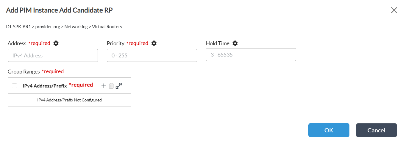
Field Description Address (Required) Enter the IPv4 address for candidate RP. Priority (Required)
Enter the candidate RP priority.
Range: 0 through 255
Default: None
Hold Time
Enter the amount of time the candidate RP advertisement is valid.
Range: 3 through 65535
Default: None
Group Ranges (Required) Click the
 Add icon and enter one or more addresses/prefixes for the IPv4 multicast group range.
 - Click OK.
- Select the Anycast RP tab, and click the
 Add icon.

- In the Add PIM Instance Add Anycast RP popup window, enter information for the following fields.

Field Description Address (Required) Enter the IPv4 address for anycast RP. Local Address Click and enter the local IPv4 address in the Local Address field. Local Interface Click and enter the local interface name in the Local Interface field. Local Network Click and enter the network name in the Local Network field. RP Click the
 Add icon, and then enter the IPv4 address of the other RP in the anycast RP set. If multiple RPs are in the set, add the IPv4 addresses for each of the RPs in the set.
 - Click OK.
- Select the Candidate BSR tab, and enter information for the following fields.

Field Description Address Enter the address for the candidate BSR. Priority
Enter the candidate BSR priority. A higher priority is preferred for candidate BSR.
Range: 0 through 255
Hash Mask Length
Enter the length, in bits, of the mask to use in the hash function.
Range: 4 through 32
- Click OK. The Configure Virtual Router popup window displays the configured PIM instance for the tenant.
Note that, by default, the PIM instance global timers apply to all PIM-enabled interfaces and networks. To override the global values, configure timers at the interface or network level.
Configure IGMP
Internet Group Management Protocol (IGMP) is a multicast protocol that is used by hosts and adjacent routers on IP networks to establish and manage multicast group memberships. You enable IGMP between a host device and a local multicast router. A host requests membership to a multicast group by sending& join requests to any local multicast router.
VOS devices support IGMP versions 1, 2, and 3, and they support IGMP groups. You use IGMPv3, which has the include filter, with PIM-SSM.
By default, IGMPv2 is enabled on all the PIM-enabled interfaces or networks. You must create an IGMP instance to enable IGMPv3 on an interface or network or to override default properties such as timers, immediate leave, and IGMP static groups.
To configure IGMP:
- In Director view:
- Select the Configuration tab in the top menu bar.
- Select Templates > Device Templates in the horizontal menu bar.
- Select an organization in the left menu bar.
- Select a post-staging template in the main pane. The view changes to Appliance view.
- Select the Configuration tab in the top menu bar.
- Select Networking > Virtual Routers in the left menu bar. The screen displays all configured virtual routers.
- Click the
 Add icon. The Configure Virtual Router popup window displays with the Virtual Router Details tab selected by default.

- In the Instance Name field, enter a name for the new virtual router.
- Select the IGMP tab in the horizontal menu bar. The main IGMP screen displays.

- Click the
 Add icon. In the Add IGMP Instance popup window, enter information for the following fields.

Field Description Instance ID (Required) Enter the instance ID assigned to IGMP. Note that, for a given tenant, PIM and IGMP have the same instance ID.
Robust Count Enter the number of IGMP group query messages the router sends when it receives an IGMP leave message on a shared network.
Range: 2 through 7
Default: 2
Query Interval
Enter how often the IGMP router sends general host-query messages on each attached network to inquire about membership information.
Range: 2 through 31744 seconds
Default: 125 seconds
Query Last Member Interval
Enter the maximum amount of time between group-specific query messages.
Range: 1 through 25 seconds
Default: 1 second
Query Response Interval Enter the maximum amount of time between the router sending a host-query message and the router receiving a response from a host.
Range: 1 through 25 seconds
Default: 10 seconds
- Select the Interfaces tab, then click the
 Add icon. In the Add IGMP Instance Add Interfaces popup window, enter information for the following fields.

Field Description Interface (Required)
Select the interface on which to enable IGMP.
Version
Enter IGMP version.
Default: 2
Group Limit Enter the limit for the number of multicast group joins for logical interfaces.
Range: 0 through 32767
Source Limit Enter the limit for the number of multicast source joins for logical interfaces.
Range: 0 through 32767
IGMP Join Source and Group Filter (For Releases 23.1.1 and later.) Select the extended access list that specifies source and group destination IP addresses to filter IGMP join messages.
IGMP Join Group Filter (For Releases 23.1.1 and later.) Select the access list that specifies group destination IP addresses to filter IGMP join messages.
Disable Click to disable IGMP on the interface. Immediate Leave Click to flush IGMP group cache entries immediately after the interface receives an IGMP leave message. Passive Click to indicate that the router is a passive listener that does not advertise itself. IGMP Group IP Address Click the
 Add icon. In the Add IGMP Instance Add Interfaces Add Group screen, enter information for the following fields.

- IGMP Group IP Address (Required)—Enter the static group IP address for IGMP.
- Source—Enter the source IP address corresponding to a static IGMPv3 group.
- Click OK.
- Click OK.
- In the Add IGMP Instance screen, select the Networks tab, then click the Add icon.

- In the Add IGMP Instance Add Networks popup window, enter information for the following fields.

Field Description Network (Required)
Select the network on which to enable IGMP.
Version
Enter the IGMP version.
Default: 2
Group Limit Enter the limit for the number of multicast group joins for logical interfaces.
Range: 0 through 32767
Source Limit Enter the limit for the number of multicast source joins for logical interfaces.
Range: 0 through 32767
IGMP Join Source and Group Filter (For Releases 23.1.1 and later.) Select the extended access list that specifies source and group destination IP addresses to filter IGMP join messages.
IGMP Join Group Filter (For Releases 23.1.1 and later.) Select the access list that specifies group destination IP addresses to filter IGMP join messages.
Disable Click to disable IGMP on the network. Immediate Leave Click to flush IGMP group cache entries immediately after the network receives an IGMP leave message.. Passive Click to indicate that the router is a passive listener that does not advertise itself. IGMP Group IP Address Click the
 Add icon. In the Add IGMP Instance Add Networks Add Group screen, enter information for the following fields.
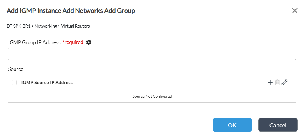
- IGMP Group IP Address (Required)—Enter the static group IP address for IGMP.
- Source—Enter the source IP address corresponding to a static IGMPv3 group.
- Click OK.
- Click OK. The Configure Virtual Router window displays the configured IGMP instance.

Configure an Access List
For Releases 23.1.1 and later.
You can configure an access list that a network device applies to IP addresses to manage and filter traffic. The access list must include a term to deny all traffic except the IP addresses that are allowed to manage the device. You can apply a standard access list, which filters traffic based on the source IP address, and an extended access list, which filters traffic based on the source and destination IP addresses.
To configure an access list:
- In Director view:
- Select the Configuration tab in the top menu bar.
- Select Templates > Device Templates in the horizontal menu bar.
- Select an organization in the left menu bar.
- Select a post-staging template in the main pane. The view changes to Appliance view.
- Select the Configuration tab in the top menu bar.
- Select Networking > Virtual Routers in the left menu bar. The screen displays all configured virtual routers.
- Click the
 Add icon. The Configure Virtual Router window displays with the Virtual Router Details tab selected by default.

- In the Instance Name field, enter a name for the new virtual router.
- Select the Access List tab in the horizontal menu bar. The following screen displays.

- Select the Access List subtab and click the + Add icon. In the Add Access List popup window, enter information for the following fields.
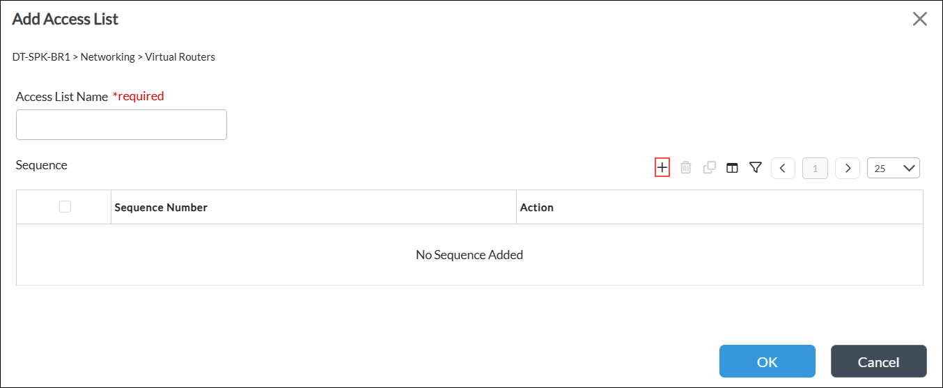
Field Description Access List Name (Required) Enter a name for the standard access list for routing filters.
Sequence Click the
 Add icon. In the Add Access List Add Sequence window, enter information for the following fields.
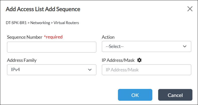
- Sequence Number (Required)—Enter a sequence number for the access list term (Permit or Deny), which defines the order of rules evaluation within an access list.
- Action—Select an action:
- Deny—Select to exclude IP addresses matching this rule from the access list.
- Permit—Select to include IP addresses matching this rule in the access list.
- Address Family—Select the address family:
- IPv4
- IPv6
- IP Address/Mask—Enter the IPv4 or IPv6 address.
- Click OK.
- Click OK.
- Select the Extended Access List subtab and click the + Add icon.

-
In the Add Extended Access List window, enter information for the following fields.

Field Description Access List Name (Required) Enter a name for the extended access list for routing filters. Sequence Click the
 Add icon. In the Add Access List Add Sequence screen, enter information for the following fields.
- Sequence Number (Required)—Enter a sequence number of an extended access list term which defines the order of rules evaluation within an extended access list.
- Action—Select an action:
- Deny—Select to exclude source and destination IP addresses that the selected access list matches.
- Permit—Select to include source and destination IP addresses that the selected access list matches.
- Source—Select the name of the standard access list to match for source address.
- Destination—Select the name of the standard access list to match for destination address.
- Click OK.
-
Click OK.
Monitor the Multicast Configuration
This section describes CLI commands you use to monitor the multicast configuration on a branch. You can access a branch CLI from a Director node, as described in Access the CLI. You can also monitor your configuration using the Director screens shown in Monitor Hubs and Spokes.
To monitor a multicast configuration use the following CLI commands.
To display PIM interfaces, issue the show pim interface routing-instance command. For example:
admin@Hub1-cli> show pim interface brief Tenant1-LAN-VR
routing-instance: Tenant1-LAN-VR
Family: INET

V = Version, NbrCnt = Neighbor Count
DR = Designated Router, P2P = Point-to-point link

Name               IP V State        NbrCnt DR address
vni-0/1.101        v4 2 NotDR        1      172.41.101.2
tvi-0/111.0        v4 2 DR           0      0.0.0.0
dtvi-0/246         v4 2 NotDR        1      10.100.13.106
To display PIM neighbors, issue the show pim neighbor (brief | detail) routing-instance command. For example:
admin@Hub1-cli> show pim neighbor brief Tenant1-LAN-VR
Instance: Tenant1-LAN-VR
B = Bidirectional Capable, G = Generation Identifier,
H = Hello Option Holdtime, L = Hello Option LAN Prune Delay,
P = Hello Option DR Priority, T = Tracking Bit

Interface            IP  V Mode        Option   Uptime    Neighbor addr
---------           ---- - ----        ------   ------    -------------
vni-0/1.101         ipv4 2 sparse      PGH      2w4d08h   172.41.101.2
dtvi-0/246          ipv4 2 sparse      PLGH     2w4d07h   10.100.13.106
To display PIM (*,G) joins, issue the show pim join extensive routing-instance command. For example:
Note: In the notation PIM (*,G), the asterisk (*) means any source sending to the multicast group G, and G is the multicast group.
admin@Hub1-cli> show pim join extensive Tenant1-LAN-VR
routing-instance: Tenant1-LAN-VR
Family: INET
*,G table
Group: 227.1.1.1
    Source: *
    RP: 1.1.1.1
    Upstream interface: Local
    Upstream neighbor: 0.0.0.0
    Upstream state: Local RP
    Uptime: 5d07h39m
    Downstream neighbors:
        Interface: dtvi-0/246(Branch1-Mpls)
            Uptime: 5d07h39m
            Remaining time for join expiry: 00:02:50
            Assert state: No info
            Assert winner address: N/A
To display PIM (S,G) joins, issue the show pim join extensive routing-instance inet sg command. For example:
admin@Hub1-cli> show pim join extensive Tenant1-LAN-VR inet sg
S,G table
Group: 227.1.1.1
    Source: 172.16.1.1
    Upstream interface: vni-0/1.101
    Upstream neighbor: 172.41.101.2
    Upstream state: Join to Source
    Uptime: 06:51:52
    Downstream neighbors:
    Interface: dtvi-0/246(Branch1-Mpls)
            Uptime: 5d07h43m
            Remaining time for join expiry: 00:02:41
            Assert state: No info
            Assert winner address: N/A
To display a list of the PIM RPs, issue the show pim rps brief routing-instance command. For example:
admin@Hub1-cli> show pim rps brief Tenant1-LAN-VR
Instance: Tenant1-LAN-VR
RP address          Type        Mode        Group prefixes
-----------------   --------    --------    ----------------
1.1.1.1             static      sparse      227.0.0.0/8
0.0.0.0             static      ssm         232.0.0.0/8
To display a list of the anycast RPs, issue the show pim anycast-rps brief routing-instance command. For example:
admin@Hub1-cli> show pim anycast-rps brief Tenant1-LAN-VR
Instance: Tenant1-LAN-VR
Anycast RP address      RP Address          LOCAL
------------------      ----------          -----
1.1.1.1                 172.41.101.1        true
1.1.1.1                 172.42.101.1        false
To display PIM statistics for a named routing instance, issue the show pim statistics routing-instance routing-instance command.
For Releases 21.2.1 and later, to display RPF information for an IP address, issue the show route multicast-rpf ipv4-address command. You typically check the RPF for a multicast source or an RP. For example:
admin@sdwan-br1-cli> show route multicast-rpf 192.168.100.3
Routes for Routing instance : global  AFI: ipv4  SAFI: unicast

Routes for Routing instance : rti-1  AFI: ipv4  SAFI: unicast
[+] - Active Route
Routing entry for 192.168.100.0 (mask 255.255.255.0) [+]
Known via 'netmgmt', distance 1, metric 10, forward metric 10
  Redistributing via netmgmt
  Last update from 192.168.1.2 00:01:56 ago<
Routing Descriptor Blocks:
* 192.168.1.2 , via Indirect 00:01:56 ago
For Releases 21.2.1 and later, to display RPF information for an IP address for a routing instance, issue the show route multicast-rpf routing-instance routing-instance ipv4-address command. For example:
admin@sdwan-br1-cli> show route multicast-rpf routing-instance rti-1 192.168.100.3
Routes for Routing instance : rti-1  AFI: ipv4  SAFI: unicast
[+] - Active Route

Routing entry for 192.168.100.0 (mask 255.255.255.0) [+]
Known via 'netmgmt', distance 1, metric 10, forward metric 10
	   Redistributing via netmgmt
	   Last update from 192.168.1.2 00:01:27 ago
Routing Descriptor Blocks:
* 192.168.1.2 , via Indirect 00:01:27 ago
Static Rendezvous Point Configuration Example
This section provides an example of how to configure a static rendezvous point (RP) for a Protocol Independent Multicast (PIM) network. In a static RP configuration, you manually configure all leaf routers (those directly connected to source devices, receiving devices, or intermediate routers) with the IP address of the RP along with the group mapping.
Configure Static RP
In this example, a multicast-enabled branch (typically a spoke) is connected to a hub that is acting as an RP for a multicast group G. The source S is located somewhere in the data center, which would typically be behind the hub. In this example, the first-hop router (FHR) is in the data center, the hub is acting as an RP, and a branch (spoke) acts as a last-hop router (LHR). The following figure shows the topology of the configuration example:

You must place routers into the same cluster list. A cluster list is a set of branches that form PIM memberships. Only branches within a cluster list are considered PIM neighbors.
To configure static RP, you do the following:
- Configure the hub:
- Configure the hub as an RP.
- Configure a cluster list for IP multicast over the SD-WAN overlay.
- Configure the spoke—Apply the static RP configuration to all branches (spokes).
- Bind parameters—If needed, bind parameterized values.
- Push configurations—Push the templates to the branch devices using the Commit Template action.
For this configuration example, note the following:
- You perform the configuration from the Director node.
- You apply the configuration changes to templates.
- By default, IGMPv2 is enabled on all PIM-enabled interfaces.
Configure the Hub
To configure the hub as an RP:
- In Director view:
- Select the Configuration tab in the top menu bar.
- Select Templates > Device Templates in the horizontal menu bar.
- Select a post-staging template in the main pane. The view changes to Appliance view.
- Select Networking
 > Virtual Routers in the left menu bar.
 - Select a LAN-VR router in the main pane. The Edit LAN-VR screen displays.
- Select PIM in the left menu bar.
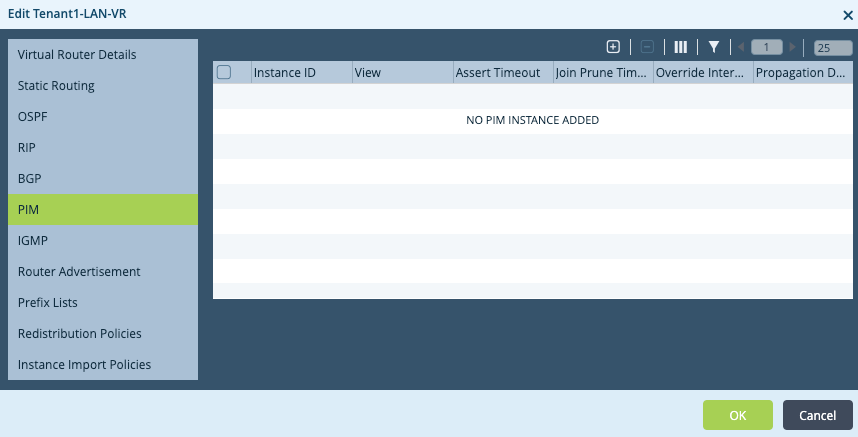
- Click the
 Add icon. The Add PIM Instance popup window displays.
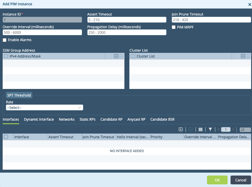
- In the Instance ID field, enter a number for the instance identifier. The value can be a number from 1 through 65535. In this example, the instance ID is 1.
- In the Cluster List table, click the
 Add icon.
 - Enter a number for the cluster list, which can be from 1 through 65535. In this example, the cluster list number is 1. Place hubs and spokes into the same cluster list so that they can form PIM memberships.
- Select the Interfaces tab.
- Click the
 Add icon. The Add PIM Instance > Add Interface popup window displays.

- In the Interface field, select an interface. In this example, the interface is tvi-0/111.
- Click OK.

- Select the Networks tab.
- Click the
 Add icon. The Add PIM Instance > Add Networks popup window displays.

- In the Network field, select a network.
- Click OK.

- Select the Static RPs tab.
- Click the
 Add icon. The Add PIM Instance > Add Static RPs popup window displays.

- In the RP Address field, enter the IP address of the RP for the multicast group. In this example, the IP address is 1.1.1.1.
- In the Group Ranges table, click the
 Add icon. The Add PIM Instance > Add Static RPs > Add Group Ranges popup window displays.
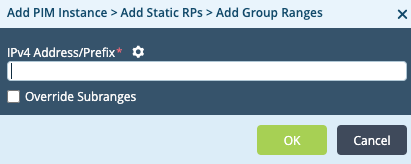
- In the IPv4 Address/Prefix field, enter the IP address and mask of the multicast group. In this example, this is 227.0.0.0/8.
- Click OK.

- Click OK to add the static RP.
- Click OK to add the PIM instance.
Configure a Spoke
To configure a spoke:
- In Director view:
- Select the Configuration tab in the top menu bar.
- Select Templates > Device Templates in the horizontal menu bar.
- Select a post-staging template in the main pane. The view changes to Appliance view.
- Select Networking
 > Virtual Routers in the left menu bar.
 - Select a LAN-VR router in the main pane. The Edit LAN-VR screen displays.
- Select PIM in the left menu bar.

- Click the
 Add icon. The Add PIM Instance popup window displays.

- In the Instance ID field, enter a number for the instance identifier. The value can be a number from 1 through 65535. In this example, the instance ID is 1. This number is local to the spoke and does not need to match the hub Instance ID.
- In the Cluster List table, click the
 Add icon.
 - Enter a number for the cluster list, which can be from 1 through 65535. In this example, the cluster list number is 1. Assign spokes the same cluster list number you assigned to the hub.
- Select the Interfaces tab.
- Click the
 Add icon. The Add PIM Instance > Add Interface popup window displays.

- In the interface field, select the interface. Here, we use interface tvi-0/111.
- Click OK.
- Select the Networks tab.
- Click the
 Add icon. The Add PIM Instance > Add Networks popup window displays.

- In the Network field, select a network.
- Click OK.
- Select the Static RPs tab.
- Click the
 Add icon. The Add PIM Instance > Add Static RPs popup window displays.

- In the RP Address field, enter the IP address of the RP. In this example, the IP address is 1.1.1.1.
- In the Group Ranges table, click the
 Add icon. The Add PIM Instance > Add Static RPs > Add Group Ranges popup window displays.

- In the IPv4 Address/Prefix field, enter the IP address and mask of the multicast group. In this example, this is 227.0.0.0/8.
- Click OK.

- Click OK to add the static RP.
- Click OK to add the PIM instance.
Bind Parameter Values
For any parameterized fields you chose in the previous steps, you must provide values and then redeploy the configuration.
To provide values for parameterized fields:
- In Director view, select the Workflows tab in the top menu bar.
- Select Devices > Devices in the left menu bar.
- Select a device in the main pane.
- Select the Bind Data tab.
- Locate the variable name in the list. Use the slider bar to display additional variables.
- Enter values for the parameterized fields.
- Click Redeploy.
Push the Configurations
After you complete the hub and spoke configurations and bind values for any parameterized fields, push the configurations to the devices using the Commit Template action.
To push the configuration:
- In Director view, select the Workflows tab in the top menu bar.
- Select Devices > Devices in the left menu bar.
- Select a device from the main pane.
- Click Commit Template in the top menu bar.

Monitor Hubs and Spokes
After you configure the hubs and spokes, you can view device information on the Director Monitor screens and from the CLI.
In Director, you monitor a hub or a spoke from the Services tab. To display the Services tab for the hub or spoke:
- In Director view, select the Monitor tab in the top menu bar.
- In the left menu bar, double-click the provider organization for the hub or spoke to display tenant organizations.
- In the left menu bar, select the tenant organization for the hub or spoke.
- Select the Devices tab.
- In the main pane, click on the name of the hub or spoke. The Monitor screen for the device displays, and the Summary tab is selected.
- Select the Services tab.

- Continue with the steps described in the sections below.
Monitor Hubs
This section describes how to monitor the hubs.
Display PIM Interfaces
From Director:
- Display the Services tab, as described in Monitor Hubs and Spokes, above.
- In the Networking pane, click PIM.
- Select the routing instance from the drop-down list. Two additional drop-down lists display.
- Select Interface from the second drop-down.
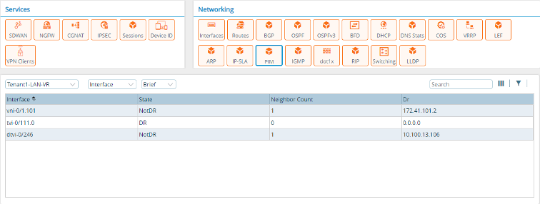
- Select Brief from the third drop-down to display PIM interface information. Note that in the following screenshot, 10.100.13.106 is the IP address of the spoke.
From the CLI:
admin@Hub1-cli> show pim interface brief Tenant1-LAN-VR
routing-instance: Tenant1-LAN-VR
Family: INET

V = Version, NbrCnt = Neighbor Count
DR = Designated Router, P2P = Point-to-point link

Name               IP V State        NbrCnt DR address
vni-0/1.101        v4 2 NotDR        1      172.41.101.2
tvi-0/111.0        v4 2 DR           0      0.0.0.0
dtvi-0/246         v4 2 NotDR        1      10.100.13.106
Display PIM Neighbors
From Director:
- Display the Services tab, as described in Monitor Hubs and Spokes, above.
- In the Networking pane, click PIM.
- Select the routing instance from the drop-down list. Two additional drop-down lists display.
- Select Neighbor from the second drop-down.
- Select Brief from the third drop-down to display PIM neighbor information.

From the CLI:
admin@Hub1-cli> show pim neighbor brief Tenant1-LAN-VR
Instance: Tenant1-LAN-VR
B = Bidirectional Capable, G = Generation Identifier,
H = Hello Option Holdtime, L = Hello Option LAN Prune Delay,
P = Hello Option DR Priority, T = Tracking Bit

Interface            IP  V Mode        Option   Uptime    Neighbor addr
---------           ---- - ----        ------   ------    -------------
vni-0/1.101         ipv4 2 sparse      PGH      2w4d08h   172.41.101.2
dtvi-0/246          ipv4 2 sparse      PLGH     2w4d07h   10.100.13.106
Display PIM (*,G) Joins
From Director:
- Display the Services tab, as described in Monitor Hubs and Spokes, above.
- In the Networking pane, click PIM.
- Select the routing instance from the drop-down list. Two additional drop-down lists display.
- Select Join from the second drop-down.
- Select Star-g from the third drop-down.

- Click View to display the PIM (*,G) OIF list.
From the CLI:
admin@Hub1-cli> show pim join extensive Tenant1-LAN-VR
routing-instance: Tenant1-LAN-VR
Family: INET
*,G table
Group: 227.1.1.1
    Source: *
    RP: 1.1.1.1
    Upstream interface: Local
    Upstream neighbor: 0.0.0.0
    Upstream state: Local RP
    Uptime: 5d07h39m
    Downstream neighbors:
        Interface: dtvi-0/246(Branch1-Mpls)
            Uptime: 5d07h39m
            Remaining time for join expiry: 00:02:50
            Assert state: No info
            Assert winner address: N/A
Display PIM (S,G) Joins
From Director:
- Display the Services tab, as described in Monitor Hubs and Spokes, above.
- In the Networking pane, click PIM.
- Select the routing instance from the drop-down list. Two additional drop-down lists display.
- Select Join from the second drop-down.
- Select Sg from the third drop-down.

- Click View to display the PIM (S,G) OIF list.
From the CLI:
admin@Hub1-cli> show pim join extensive Tenant1-LAN-VR inet sg
S,G table
Group: 227.1.1.1
    Source: 172.16.1.1
    Upstream interface: vni-0/1.101
    Upstream neighbor: 172.41.101.2
    Upstream state: Join to Source
    Uptime: 06:51:52
    Downstream neighbors:
    Interface: dtvi-0/246(Branch1-Mpls)
            Uptime: 5d07h43m
            Remaining time for join expiry: 00:02:41
            Assert state: No info
            Assert winner address: N/A
Display PIM RPs
From Director:
- Display the Services tab, as described in Monitor Hubs and Spokes, above.
- In the Networking pane, click PIM.
- Select the routing instance from the drop-down list. Two additional drop-down lists display.
- Select RPs from the second drop-down.
- Select Brief from the third drop-down.

From the CLI:
admin@Hub1-cli> show pim rps brief Tenant1-LAN-VR
Instance: Tenant1-LAN-VR
   RP address          Type        Mode         Group prefixes
-----------------    --------    --------    --------------------
1.1.1.1               static      sparse             227.0.0.0/8
0.0.0.0               static      ssm                232.0.0.0/8
Monitor the Spokes
This section describes how to monitor the spokes.
Display PIM Interfaces
From Director:
- Display the Services tab, as described in Monitor Hubs and Spokes, above.
- In the Networking pane, click PIM.
- Select the routing instance from the drop-down list. Two additional drop-down lists display.
- Select Interface from the second drop-down.
- Select Brief from the third drop-down to display PIM interface information.

From the CLI:
admin@Branch1-Mpls-cli> show pim interface brief Tenant1-LAN-VR
routing-instance: Tenant1-LAN-VR
Family: INET

V = Version, NbrCnt = Neighbor Count
DR = Designated Router, P2P = Point-to-point link

Name               IP V State        NbrCnt DR address
vni-0/3.101        v4 2 DR           1      172.18.101.4
vni-0/3.102        v4 2 DR           1      172.18.102.4
vni-0/3.103        v4 2 DR           1      172.18.103.4
vni-0/3.104        v4 2 DR           1      172.18.104.4
vni-0/3.105        v4 2 DR           1      172.18.105.4
dtvi-0/728         v4 2 DR           1      10.100.13.106
Display PIM Neighbors
From Director:
- Display the Services tab, as described in Monitor Hubs and Spokes, above.
- In the Networking pane, click PIM.
- Select the routing instance from the drop-down list. Two additional drop-down lists display.
- Select Neighbor from the second drop-down.
- Select Brief from the third drop-down to display PIM neighbor information.

From the CLI:
admin@Branch1-Mpls-cli> show pim neighbor brief Tenant1-LAN-VR

Instance: Tenant1-LAN-VR
B = Bidirectional Capable, G = Generation Identifier,
H = Hello Option Holdtime, L = Hello Option LAN Prune Delay,
P = Hello Option DR Priority, T = Tracking Bit
Interface            IP  V Mode        Option   Uptime    Neighbor addr
---------           ---- - ----        ------   ------    -------------
vni-0/3.101         ipv4 2 sparse      PLGH     00:04:38  172.18.101.3
vni-0/3.102         ipv4 2 sparse      PLGH     00:04:40  172.18.102.3
vni-0/3.103         ipv4 2 sparse      PLGH     00:04:38  172.18.103.3
vni-0/3.104         ipv4 2 sparse      PLGH     00:04:39  172.18.104.3
vni-0/3.105         ipv4 2 sparse      PLGH     00:04:41  172.18.105.3
dtvi-0/728          ipv4 2 sparse      PLGH     2w4d07h   10.100.13.101
Display PIM (*,G) Joins
From Director:
- Display the Services tab, as described in Monitor Hubs and Spokes, above.
- In the Networking pane, click PIM.
- Select the routing instance from the drop-down list. Two additional drop-down lists display.
- Select Join from the second drop-down.
- Select Star-g from the third drop-down to display PIM (*,G) join information.

- Click View in the Oif column to display downstream neighbors.

From the CLI:
admin@Branch1-Mpls-cli> show pim join extensive Tenant1-LAN-VR
routing-instance: Tenant1-LAN-VR
Family: INET
*,G table
Group: 227.1.1.1
    Source: *
    RP: 1.1.1.1
    Upstream interface: dtvi-0/728(Hub1)
    Upstream neighbor: 10.100.13.101
    Upstream state: Join to RP
    Uptime: 5d08h21m
    Downstream neighbors:
        Interface: vni-0/3.101
            Uptime: 5d08h21m
            Remaining time for join expiry: Infinite
            Assert state: No info
            Assert winner address: N/A
        Interface: vni-0/3.102
            Uptime: 5d08h21m
            Remaining time for join expiry: Infinite
            Assert state: No info
            Assert winner address: N/A
        Interface: vni-0/3.103
            Uptime: 5d08h21m
            Remaining time for join expiry: Infinite
            Assert state: No info
Display PIM (S,G) Joins
From Director:
- Display the Services tab, as described in Monitor Hubs and Spokes, above.
- In the Networking pane, click PIM.
- Select the routing instance from the drop-down list. Two additional drop-down lists display.
- Select Join from the second drop-down.
- Select Sg from the third drop-down.

- Click View in the Oifs column to display outgoing interfaces.

From the CLI:
admin@Branch1-Mpls-cli> show pim join extensive Tenant1-LAN-VR inet sg
S,G table
Group: 227.1.1.1
    Source: 172.16.1.1
    Upstream interface: dtvi-0/728(Hub1)
    Upstream neighbor: 10.100.13.101
    Upstream state: Join to Source
    Uptime: 5d08h21m
    Downstream neighbors:
        Interface: vni-0/3.101
            Uptime: 5d08h21m
            Remaining time for join expiry: Infinite
            Assert state: No info
            Assert winner address: N/A
        Interface: vni-0/3.102
            Uptime: 5d08h21m
            Remaining time for join expiry: Infinite
            Assert state: No info
            Assert winner address: N/A
        Interface: vni-0/3.103
            Uptime: 5d08h21m
            Remaining time for join expiry: Infinite
            Assert state: No info
            Assert winner address: N/A
        Interface: vni-0/3.104
            Uptime: 5d08h21m
            Remaining time for join expiry: Infinite
            Assert state: No info
            Assert winner address: N/A
        Interface: vni-0/3.105
            Uptime: 5d08h21m
            Remaining time for join expiry: Infinite
            Assert state: No info            Assert winner address: N/A
Display IGMP Information
From Director:
- Display the Services tab, as described in Monitor Hubs and Spokes, above.
- In the Networking pane, click IGMP.
- Select the routing instance from the drop-down list. A second drop-down list displays.
- Select Group from the second drop-down.
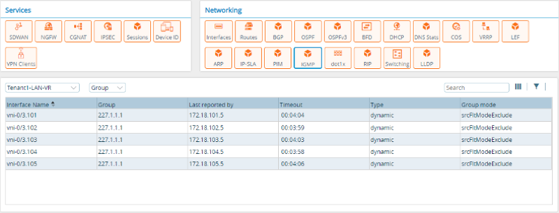
From the CLI:
admin@Branch1-Mpls-cli> show igmp group Tenant1-LAN-VR
routing-instance: Tenant1-LAN-VR

Interface   : vni-0/3.101
Group       : 227.1.1.1
            Group mode       :  Exclude
            Last reported by : 172.18.101.5
            Timeout :  00:03:30
            Type  :  Dynamic

Interface   : vni-0/3.102
Group       : 227.1.1.1
            Group mode       :  Exclude
            Last reported by : 172.18.101.5
            Timeout :  00:03:30
            Type  :  Dynamic

Interface   : vni-0/3.103
Group       : 227.1.1.1
            Group mode       :  Exclude
            Last reported by : 172.18.101.5
            Timeout :  00:03:30
            Type  :  Dynamic

Interface   : vni-0/3.104
Group       : 227.1.1.1
            Group mode       :  Exclude
            Last reported by : 172.18.101.5
            Timeout :  00:03:30
            Type  :  Dynamic

Interface   : vni-0/3.105
Group       : 227.1.1.1
            Group mode       :  Exclude
            Last reported by : 172.18.101.5
            Timeout :  00:03:30
            Type  :  Dynamic
PIM-Only Anycast Rendezvous Point Configuration Example
This section provides an example of how to configure an anycast rendezvous point (RP) in a Protocol Independent Multicast Sparse Mode (PIM-SM) network. Anycast RP provides load sharing and allows you to configure redundant RPs. In addition, the bootstrap router (BSR) mechanism available in PIMv2 permits only one RP to be active for a given group G at any point in time. Anycast RP allows multiple RPs to be active at the same time for a group G. You configure two or more RPs with the same IP address, which is, known as the anycast RP address.
Typically, you use a loopback interface for configuring the anycast RP address. This anycast RP address must be reachable through all PIM-enabled routing instances within the multicast domain. You configure the anycast RP address in all PIM routing instances for a given group prefix list when you configure the static RP. To ensure that each RP that provides anycast RP functionality knows about its peers, you configure the routable IP address of each anycast RP peer on each of the anycast RPs.
With anycast RP, a PIM routing instance always connects to its closest RP. This means that it is possible for the source and receiver to send join messages to two different anycast RP routing instances. For this reason, it is essential that all anycast RP peers know the source information.
The VOS anycast RP solution is based on the PIM-only anycast RP mechanism, as described in RFC 4610.
Enterprise customers typically use anycast RP to meet fault-tolerance requirements and RP redundancy within a single multicast domain that might span multiple geographies. Consider an example in which a multicast domain spans North America and Europe, with each region having its own RP. All PIM-enabled routing instances in North America select the RP located in North America, and all PIM-enabled routing instances in Europe select the RP located in Europe. Routing instances in North America send their join and registration messages to the metrically closest anycast RP and keep the remote RP (Europe) as backup, and vice versa. Route selection to the anycast RP address is determined by the preference or metric of the IP address in the route table. If the North American RP goes down, joins and registration messages are sent to an RP in Europe. Because the anycast RP address is the same across all RPs, routing instances in the multicast domain are agnostic with regards to an RP failure.
Configure PIM-Only Anycast RP
The following configuration example shows a multicast-enabled branch (typically, a spoke) that is topologically connected to two RPs (typically hubs) in two different geographies. Source S is located somewhere in a data center, which would typically be behind the hubs that are acting as RPs. The first-hop router (FHR) is in the data center. The hubs are acting as RPs, and it is on these hubs that this example configures the anycast RP. A branch acts as a last-hop router (LHR).
In this configuration, you place the routers in the same cluster list. A cluster list is a set of branches that form PIM memberships. Only branches in the cluster list are considered PIM neighbors.
The following figure shows the topology for this example.
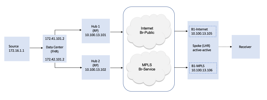
To configure PIM-only anycast RP, you do the following:
- Configure the hubs:
- Configure the hubs as anycast RPs.
- Configure a cluster list for IP multicast over the SD-WAN overlay.
- Configure the spoke—Apply the static RP configuration on all branches (spokes), and apply the static RP configuration on all routing instances, including the RPs, instead of using the BSR mechanism.
- Bind parameters—If needed, bind parameterized values.
- Push configurations—Push templates to the branch devices using the Commit Template action.
For this configuration example, note the following:
- You perform the configuration from the Director node.
- You apply the configuration changes to templates.
- The configuration ensures that there is no single point of failure.
- The two hubs are both RPs, and you must configure both to use the IP address 1.1.1.1 for the RP functionality. This address is the /32 loopback address.
- You do not use a bootstrap router. Instead, you configure static RP on all routing instances, including the RPs.
- All routing instances in the multicast domain have two routes towards 1.1.1.1/32 in their route table. Having two routes is critical, because if the last-hop router has just one route towards 1.1.1.1/32, RP 1.1.1.1 can become isolated.
- The spoke consists of two physical devices in a branch that are operating in active-active mode. In the example, the two devices are B1-Internet and B1-MPLS.
- By default, IGMPv2 is enabled on all PIM-enabled interfaces.
Configure the Hub
To have hubs be RPs, you configure the address 1.1.1.1 for the RP functionality. You must also configure a tunnel interface. In this example, the tunnel interface is tvi-0/111 and its IP address is 1.1.1.1/32.
To configure the hub as an RP:
- In Director view:
- Select the Configuration tab in the top menu bar.
- Select Templates > Device Templates in the horizontal menu bar.
- Select a post-staging template in the main pane. The view changes to Appliance view.
- Select Networking
 > Interfaces in the left menu bar.
 - Select the Tunnel tab.
- Click the
 Add icon. The Add Tunnel Interface screen displays, and the Tunnel tab is selected.

- To add the tunnel interface:
- In the Interface field, enter slot number 0 and port number 111.
- In the Subinterfaces table, click a unit number. The Edit Subinterface popup window displays.
- In the Static Address table, click the
 Add icon, and then enter the IP address and mask 1.1.1.1/32.
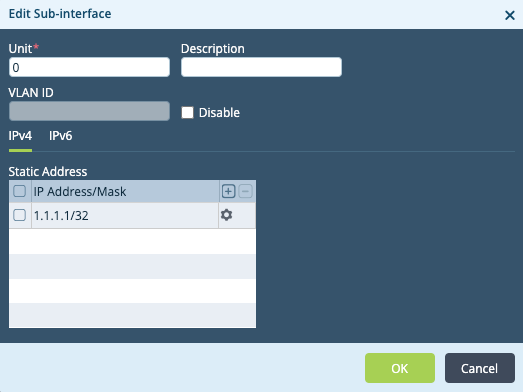
- Click OK.
- Click OK to add the tunnel.
- In the left menu bar, select Networking
 > Virtual Routers.
 - In the main pane, select a LAN-VR. The Edit LAN-VR popup window displays, and the Virtual Router Details tab is selected.
- In the Interfaces/Networks table, click the
 Add icon, select the tvi-0/111.0 interface, and click OK.

- In the left menu bar, select Others
 > Organization > Limits.
 - In the main pain, select an organization. The Edit Organization Limit popup window displays.
- Select the Traffic Identification tab.
- In the Interfaces table, click the
 Add icon, choose interface tvi-0/111.0, and click OK.

To create the PIM instance:
- Select the PIM tab in the left menu bar of the Edit LAN-VR popup window.

- Click the
 Add icon. The Add PIM Instance popup window displays.
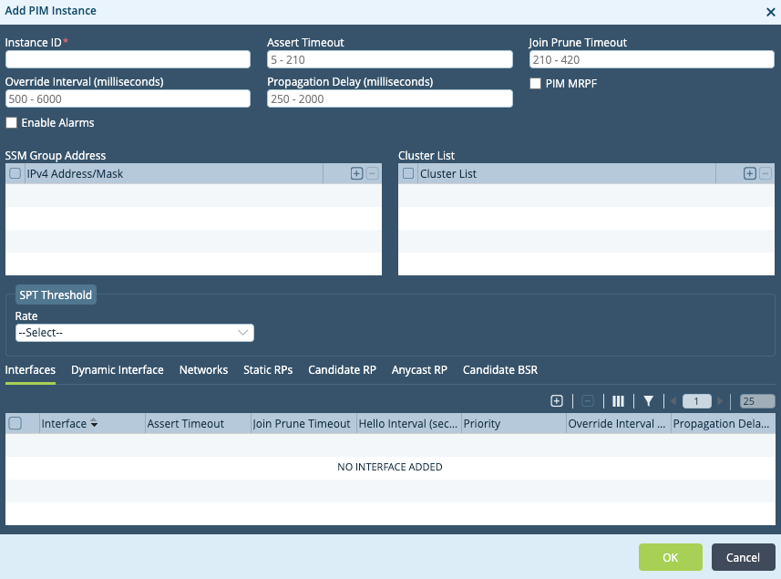
- In the Instance ID field, enter 1.
- In the Cluster List table, click the
 Add icon, and enter 1 for the cluster list number. Assign the same cluster list number to both hubs and all spokes in the example. You must configure a cluster list for IP multicast over SD-WAN.
To enable PIM on interfaces and networks:
- In the Add PIM Instance popup window, select the Interfaces tab.
- Click the
 Add icon. The Add PIM Instance > Add Interface popup window displays.

- In the Interface field, select the tvi-0/111 interface.
- Click OK.
- Select the Networks tab.
- Click the
 Add icon. The Add PIM Instance > Add Networks popup window displays.

- In the Network field, select a network.
- Click OK.
To configure the anycast RP address as the static RP for multicast groups:
- Select the Static RPs tab.
- Click the
 Add icon. The Add PIM Instance > Add Static RPs popup window displays.

- In the RP Address field, enter the IP address 1.1.1.1.
- In the Group Ranges table, click the
 Add icon. The Add PIM Instance > Add Static RPs > Add Group Ranges popup window displays.
 - Enter the IP address 227.0.0.0/8.
- Click OK.
- Select the Anycast RP tab.
- Click the
 Add icon. The Add PIM Instance > Add Anycast RP popup window displays.

- In the Address field, enter the static RP (anycast) address that is configured on the loopback interface. In this example, the address is 1.1.1.1.
- Select the local address, interface, or network to use to derive the local IP address which to use as the source IP when sending the PIM register packets to the anycast RP peers. In this example, each hub has one anycast RP peer. PIM must be enabled on the local address, interface, or network that you choose.
- To use the local IPv4 address, click Local Address and then enter the local IPv4 address, or click the
 Parameterize icon to parameterize the address.
 - To use a local interface, click Local Interface and then select an interface.
- To use a local network, click Local Network and then select a network.
- To use the local IPv4 address, click Local Address and then enter the local IPv4 address, or click the
- In the RP table, click the
 Add icon.
 - Enter the RP IPv4 IP address, or click the
 Parameterize icon to parameterize the address. The RP IPv4 address refers to the unicast address of remote anycast RP peers. This address must be reachable. In this example, each hub has one anycast RP peer.
 - Click OK.
- Click OK in the Add PIM Instance popup window.
- Click OK in the Edit LAN-VR popup window.
Configure a Spoke
To configure a spoke:
- In Director view:
- Select the Configuration tab in the top menu bar.
- Select Templates > Device Templates in the horizontal menu bar.
- Select a post-staging template in the main pane. The view changes to Appliance view.
- Select Networking
 > Virtual Routers in the left menu bar.
 - Select a LAN-VR router in the main pane. The Edit LAN-VR popup window displays.
- Select PIM in the left menu bar.

- Click the
 Add icon. The Add PIM Instance popup window displays.

- In the Instance ID field, enter a number for the instance identifier. The value can be a number from 1 through 65535. In this example, the instance ID is 1. This number is local to the spoke and does not need to match the hub Instance ID.
- In the Cluster List table, click the
 Add icon.
 - Enter a number for the cluster list, which can be from 1 through 65535. In this example, the cluster list number is 1. Assign spokes the same cluster list number you assigned to the hubs.
To enable PIM on interfaces and networks:
- In the Add PIM Instance popup window, select the Interfaces tab.
- Click the
 Add icon. The Add PIM Instance > Add Interface popup window displays.

- In the Interface field, select an interface.
- Click OK.
- Select the Networks tab.
- Click the
 Add icon. The Add PIM Instance > Add Networks popup window displays.

- Inthe Network field, select a network.
- Click OK.
To add the static RP:
- Select the Static RPs tab. The following screen displays.

- Click the
 Add icon. The Add PIM Instance > Add Static RPs popup window displays.

- In the RP Address field, enter the IP address 1.1.1.1.
- In the Group Ranges table, click the
 Add icon. The Add PIM Instance > Add Static RPs > Add Group Ranges popup window displays.

- In the IPv4 Address/Prefix field, enter the multicast group address 227.0.0.0/8.
- Click OK. The Add PIM Instance > Add Static RPs popup window displays the addresses that you just configured.
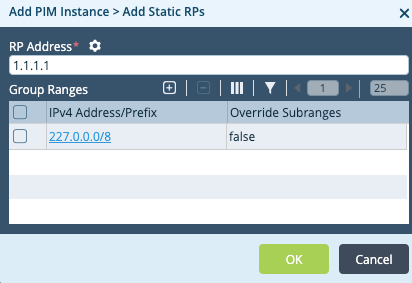
- Click OK.
- Click OK in the Add PIM Instance popup window.
- Click OK in the Edit LAN-VR popup window.
Bind Parameter Values
For any parameterized fields you chose in the previous steps, you must provide values and then redeploy the configuration.
To provide values for parameterized fields:
- In Director view, select the Workflows tab in the top menu bar.
- Select Devices > Devices in the left menu bar.
- Select a device in the main pane.
- Select the Bind Data tab.
- Locate your variable name in the list. Use the slider bar to display additional variables.
- Enter values for the parameterized fields.
- Click Redeploy
Push Configurations
After you complete the hub and spoke configurations and bind values for any parameterized fields, push the configurations to the devices using the Commit Template action.
To push the configuration:
- In Director view, select the Workflows tab in the top menu bar.
- Select Devices > Devices in the left menu bar.
- Select a device from the main pane.
- Click Commit Template in the top menu bar.

Monitor Hub 1
This section describes how to monitor Hub 1.
Display PIM Interfaces
From Director:
- Display the Services tab, as described in Monitor Hubs and Spokes, above.
- In the Networking pane, click PIM.
- Select the routing instance from the drop-down list. Two additional drop-down lists display.
- Select Interface from the second drop-down.
- Select Brief from the third drop-down to display PIM interface information. Note that 10.100.13.102 corresponds to Hub 2, 10.100.13.105 corresponds to spoke B1-Internet, and 10.100.13.106 correspond to spoke B1-MPLS. 172.41.101.2 is the data center interface connected to Hub 1.

From the CLI:
admin@Hub1-cli> show pim interface brief Tenant1-LAN-VR
routing-instance: Tenant1-LAN-VR
Family: INET

V = Version, NbrCnt = Neighbor Count
DR = Designated Router, P2P = Point-to-point link

Name               IP V State        NbrCnt DR address
vni-0/1.101        v4 2 NotDR        1      172.41.101.2
tvi-0/111.0        v4 2 DR           0      0.0.0.0
dtvi-0/246         v4 2 NotDR        1      10.100.13.106
dtvi-0/248         v4 2 NotDR        1      10.100.13.102
dtvi-0/320         v4 2 NotDR        1      10.100.13.105
Display PIM Neighbors
From Director:
- Display the Services tab, as described in Monitor Hubs and Spokes, above
- In the Networking pane, click PIM.
- Select the routing instance from the drop-down list. Two additional drop-down lists display.
- Select Neighbor from the second drop-down.
- Select Brief from the third drop-down to display PIM neighbor information.

From the CLI:
admin@Hub1-cli> show pim neighbor brief Tenant1-LAN-VR
Instance: Tenant1-LAN-VR
B = Bidirectional Capable, G = Generation Identifier,
H = Hello Option Holdtime, L = Hello Option LAN Prune Delay,
P = Hello Option DR Priority, T = Tracking Bit

Interface            IP  V Mode        Option   Uptime    Neighbor addr
---------           ---- - ----        ------   ------    -------------
vni-0/1.101         ipv4 2 sparse      PGH      2w5d04h   172.41.101.2
dtvi-0/246          ipv4 2 sparse      PLGH     03:33:23  10.100.13.106
dtvi-0/248          ipv4 2 sparse      PLGH     04:22:36  10.100.13.102
dtvi-0/320          ipv4 2 sparse      PLGH     03:17:19  10.100.13.105
Display PIM (*,G) Joins
From Director:
- Display the Services tab, as described in Monitor Hubs and Spokes, above.
- In the Networking pane, click PIM.
- Select the routing instance from the drop-down list. Two additional drop-down lists display.
- Select Join from the second drop-down.
- Select Star-g from the third drop-down.

- In the OIF column, click View to display the outgoing interfaces.

From the CLI:
admin@Hub1-cli> show pim join extensive Tenant1-LAN-VR
routing-instance: Tenant1-LAN-VR
Family: INET
*,G table
Group: 227.1.1.1
    Source: *
    RP: 1.1.1.1
    Upstream interface: Local
    Upstream neighbor: 0.0.0.0
    Upstream state: Local RP
    Uptime: 03:36:21
    Downstream neighbors:
        Interface: dtvi-0/246 (Branch1-MPLS)
            Uptime: 03:36:21
            Remaining time for join expiry: 00:03:10
            Assert state: No info
            Assert winner address: N/A
Display PIM (S,G) Joins
From Director:
- Display the Services tab, as described in Monitor Hubs and Spokes, above.
- In the networking pane, click PIM.
- Select the routing instance from the drop-down list. Two additional drop-down lists display.
- Select Join from the second drop-down.
- Select Sg from the third drop-down.

- In the OIF column, click View to display outgoing interfaces.

From the CLI:
admin@Hub1-cli> show pim join extensive Tenant1-LAN-VR inet sg
S,G table
Group: 227.1.1.1
    Source: 172.16.1.1
    Upstream interface: vni-0/1.101
    Upstream neighbor: 172.41.101.2
    Upstream state: Join to Source
    Uptime: 6d03h52m
    Downstream neighbors:
        Interface: dtvi-0/246 (Branch1-MPLS)
            Uptime: 03:38:56
            Remaining time for join expiry: 00:02:35
            Assert state: No info
            Assert winner address: N/A
Display PIM RPs
From Director:
- Display the Services tab, as described in Monitor Hubs and Spokes, above.
- In the Networking pane, click PIM.
- Select the routing instance from the drop-down list. Two additional drop-down lists display.
- Select RPs from the second drop-down.
- Select Brief from the third drop-down.

From the CLI:
admin@Hub1-cli> show pim rps brief Tenant1-LAN-VR
Instance: Tenant1-LAN-VR
RP address           Type        Mode        Group prefixes
-----------------    --------    --------    --------------
1.1.1.1              static      sparse      227.0.0.0/8
0.0.0.0              static      ssm         232.0.0.0/8
Display PIM Anycast RPs
From Director:
- Display the Services tab, as described in Monitor Hubs and Spokes, above.
- In the Networking pane, click PIM.
- Select the routing instance from the drop-down list. Two additional drop-down lists display.
- Select Anycast RPs from the second drop-down.
- Select Brief from the third drop-down.

From the CLI:
admin@Hub1-cli> show pim anycast-rps brief Tenant1-LAN-VR
Instance: Tenant1-LAN-VR
Anycast RP address      RP Address          LOCAL
------------------      ----------          -----
1.1.1.1                 172.41.101.1        true
1.1.1.1                 172.42.101.1        false
Monitor Hub 2
This section describes how to monitor Hub 1.
Display PIM Interfaces
To display PIM interfaces from Director:
- Display the Services tab, as described in Monitor Hubs and Spokes, above.
- In the Networking pane, click PIM .
- Select the routing instance from the drop-down list. Two additional drop-down lists display.
- Select Interface from the second drop-down.
- Select Brief from the third drop-down to display PIM interface information.

From the CLI:
admin@Hub2-cli> show pim interface brief Tenant1-LAN-VR
routing-instance: Tenant1-LAN-VR
Family: INET

V = Version, Nbr Cnt = Neighbor Count
DR = Designated Router, P2P = Point-to-point link

Name               IP V State        NbrCnt DR address
vni-0/1.101        v4 2 NotDR        1      172.42.101.2
tvi-0/111.0        v4 2 DR           0      0.0.0.0
dtvi-0/746         v4 2 NotDR        1      10.100.13.106
dtvi-0/756         v4 2 DR           1      10.100.13.102
dtvi-0/762         v4 2 NotDR        1      10.100.13.105
Display PIM Neighbors
From Director:
- Display the Services tab, as described in Monitor Hubs and Spokes, above.
- In the Networking pane, click PIM.
- Select the routing instance from the drop-down list. Two additional drop-down lists display.
- Select Neighbor from the second drop-down.
- Select Brief from the third drop-down to display PIM neighbor information.

From the CLI:
admin@Hub2-cli> show pim neighbor brief Tenant1-LAN-VR
Instance: Tenant1-LAN-VR
B = Bidirectional Capable, G = Generation Identifier,
H = Hello Option Holdtime, L = Hello Option LAN Prune Delay,
P = Hello Option DR Priority, T = Tracking Bit

Interface            IP  V Mode        Option   Uptime    Neighbor addr
---------           ---- - ----        ------   ------    -------------
vni-0/1.101         ipv4 2 sparse      PGH      04:39:08  172.42.101.2
dtvi-0/746          ipv4 2 sparse      PLGH     03:32:35  10.100.13.106
dtvi-0/756          ipv4 2 sparse      PLGH     04:38:11  10.100.13.101
dtvi-0/762          ipv4 2 sparse      PLGH     03:32:54  10.100.13.105
Display PIM (*,G) Joins
From Director:
- Display the Services tab, as described in Monitor Hubs and Spokes, above.
- In the Networking pane, click PIM.
- Select the routing instance from the drop-down list. Two additional drop-down lists display.
- Select Join from the second drop-down.
- Select Star-g from the third drop-down to display PIM (*,G) join information. The Monitor screen displays the message, "No data to display." This is because in the route table for B1-MPLS, Hub 2 is a non-preferred next hop for the route towards the anycast RP address 1.1.1.1. For this reason, Hub 2 does not receive PIM join messages coming from the downstream B1-MPLS, and so (*,G) does not have B1-MPLS in the outgoing interface (OIF) list.
From the CLI:
admin@Hub2-cli> show pim join extensive Tenant1-LAN-VR
routing-instance: Tenant1-LAN-VR
Family: INET
*,G table

S,G table
Group: 227.1.1.1
    Source: 172.16.1.1
    Upstream interface: vni-0/1.101
    Upstream neighbor: 172.42.101.2
    Upstream state: Not joined
    Uptime: 04:42:08
    Downstream neighbors:
Display PIM (S,G) Joins
Note that the (S,G) on Hub 2 is created from the PIM register-packet encapsulation received from Hub 1.
From Director:
- Display the Services tab, as described in Monitor Hubs and Spokes, above.
- In the Networking pane, click PIM.
- Select the routing instance from the drop-down list. Two additional drop-down lists display.
- Select Join from the second drop-down.
- Select Sg from the third drop-down.

From the CLI:
admin@Hub2-cli> show pim join extensive Tenant1-LAN-VR inet sg
S,G table
Group: 227.1.1.1
    Source: 172.16.1.1
    Upstream interface: vni-0/1.101
    Upstream neighbor: 172.42.101.2
    Upstream state: Not joined
    Uptime: 04:46:43
    Downstream neighbors:
Display PIM RPs
From Director:
- Display the Services tab, as described in Monitor Hubs and Spokes, above.
- In the Networking pane, click PIM.
- Select the routing instance from the drop-down list. Two additional drop-down lists display.
- Select RPs from the second drop-down.
- Select Brief from the third drop-down.

From the CLI:
admin@Hub2-cli> show pim rps brief Tenant1-LAN-VR
Instance: Tenant1-LAN-VR
RP address          Type        Mode        Group Prefixes
-----------------   --------    --------    --------------
1.1.1.1             static      sparse      227.0.0.0/8
0.0.0.0             static      ssm         232.0.0.0/8
Display PIM Anycast RPs
From Director:
- Display the Services tab, as described in Monitor Hubs and Spokes, above.
- In the Networking pane, click PIM.
- Select the routing instance from the drop-down list. Two additional drop-down lists display.
- Select Anycast-RPs from the second drop-down.
- Select Brief from the third drop-down.

From the CLI:
admin@Hub2-cli> show pim anycast-rps brief Tenant1-LAN-VR

Instance: Tenant1-LAN-VR

Anycast RP address      RP Address          LOCAL
------------------      ----------          -----
1.1.1.1                 172.41.101.1        false
1.1.1.1                 172.42.101.1        true
Monitor the Spokes
This section describes how to monitor the spokes.
Display PIM Interfaces
The five LAN segments VLAN 101 through 105 spanned across both the B1-MPLS and B1-Internet spoke devices. Because B1-MPLS acts as the designated router (DR) for these LAN segments, it sends PIM joins upstream.
From Director:
- Display the Services tab, as described in Monitor Hubs and Spokes, above.
- In the Networking pane, click PIM.
- Select the routing instance from the drop-down list. Two additional drop-down lists display.
- Select Interface from the second drop-down.
- Select Brief from the third drop-down to display PIM interface information.
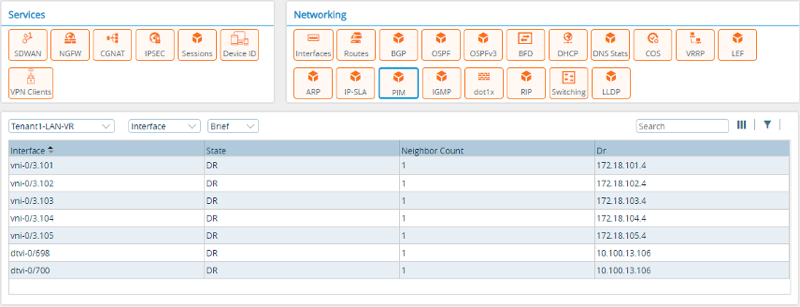
From the CLI:
admin@Branch1-Mpls-cli> show pim interface brief Tenant1-LAN-VR
routing-instance: Tenant1-LAN-VR
Family: INET

V = Version, NbrCnt = Neighbor Count
DR = Designated Router, P2P = Point-to-point link

Name               IP V State        NbrCnt DR address
vni-0/3.101        v4 2 DR           1      172.18.101.4
vni-0/3.102        v4 2 DR           1      172.18.102.4
vni-0/3.103        v4 2 DR           1      172.18.103.4
vni-0/3.104        v4 2 DR           1      172.18.104.4
vni-0/3.105        v4 2 DR           1      172.18.105.4
dtvi-0/698         v4 2 DR           1      10.100.13.106
dtvi-0/700         v4 2 DR           1      10.100.13.106
Display PIM Neighbor
From Director:
- Display the Services tab, as described in Monitor Hubs and Spokes, above.
- In the Networking pane, click PIM.
- Select the routing instance from the drop-down list. Two additional drop-down lists display.
- Select Neighbor from the second drop-down.
- Select Brief from the third drop-down to display PIM neighbor information.

From the CLI:
admin@Branch1-Mpls-cli> show pim neighbor brief Tenant1-LAN-VR

Instance: Tenant1-LAN-VR
B = Bidirectional Capable, G = Generation Identifier,
H = Hello Option Holdtime, L = Hello Option LAN Prune Delay,
P = Hello Option DR Priority, T = Tracking Bit

Interface            IP  V Mode        Option   Uptime    Neighbor addr
---------           ---- - ----        ------   ------    -------------
vni-0/3.101         ipv4 2 sparse      PLGH     04:21:55  172.18.101.3
vni-0/3.102         ipv4 2 sparse      PLGH     04:21:55  172.18.102.3
vni-0/3.103         ipv4 2 sparse      PLGH     04:21:54  172.18.103.3
vni-0/3.104         ipv4 2 sparse      PLGH     04:21:56  172.18.104.3
vni-0/3.105         ipv4 2 sparse      PLGH     04:21:56  172.18.105.3
dtvi-0/698          ipv4 2 sparse      PLGH     04:21:21  10.100.13.102
dtvi-0/700          ipv4 2 sparse      PLGH     04:37:42  10.100.13.101
Display Routing Instance Information
To display routing instance 1.1.1.1/32 from Director:
- Display the Services tab, as described in Monitor Hubs and Spokes, above.
- In the Networking pane, click PIM.
- Select the routing instance from the drop-down list. Two additional drop-down lists display.
- Select Unicast from the second drop-down.
- Select IPv4 from the third drop-down.
- Enter 1.1.1.1 in the field provided.

From the CLI. Note that the preferred route towards anycast RP address 1.1.1.1 is highlighted in the output. The next hop 10.100.13.101 corresponds to Hub 1.
admin@Branch1-Mpls-cli> show route routing-instance Tenant1-LAN-VR 1.1.1.1/32

Routes for Routing instance : Tenant1-LAN-VR  AFI: ipv4  SAFI: unicast
[+] - Active Route

Routing entry for 1.1.1.1 (mask 255.255.255.255) [+]
Known via 'BGP', distance 200,
   Redistributing via BGP
   Last update from 10.100.13.101 04:42:12 ago
Routing Descriptor Blocks:
* 10.100.13.101 , via Indirect 04:42:12 ago

Routing entry for 1.1.1.1 (mask 255.255.255.255)
Known via 'BGP', distance 200,
   Redistributing via BGP
   Last update from 10.100.13.102 04:25:48 ago
Routing Descriptor Blocks:
* 10.100.13.102 , via Indirect 04:25:48 ago
Display PIM (*,G) Join
From Director:
- Display the Services tab, as described in Monitor Hubs and Spokes, above.
- In the Networking pane, click PIM.
- Select the routing instance from the drop-down list. Two additional drop-down lists display.
- Select Join from the second drop-down.
- Select Star-g from the third drop-down.

- In the OIF column, click View to display the downstream neighbors.

From the CLI:
admin@Branch1-Mpls-cli> show pim join extensive Tenant1-LAN-VR
routing-instance: Tenant1-LAN-VR
Family: INET
*,G table
Group: 227.1.1.1
    Source: *
    RP: 1.1.1.1
    Upstream interface: dtvi-0/700 (Hub1)
    Upstream neighbor: 10.100.13.101
    Upstream state: Join to RP
    Uptime: 06:10:17
    Downstream neighbors:
        Interface: vni-0/3.101
            Uptime: 06:10:11
            Remaining time for join expiry: Infinite
            Assert state: No info
            Assert winner address: N/A
        Interface: vni-0/3.102
            Uptime: 06:10:14
            Remaining time for join expiry: Infinite
            Assert state: No info
            Assert winner address: N/A
        Interface: vni-0/3.103
            Uptime: 06:10:16
            Remaining time for join expiry: Infinite
            Assert state: No info
            Assert winner address: N/A
        Interface: vni-0/3.104
            Uptime: 06:10:12
            Remaining time for join expiry: Infinite
            Assert state: No info
            Assert winner address: N/A
        Interface: vni-0/3.105
            Uptime: 06:10:18
            Remaining time for join expiry: Infinite
            Assert state: No info
            Assert winner address: N/A
Display PIM (S,G) Joins
From Director:
- Display the Services tab, as described in Monitor Hubs and Spokes, above.
- In the Networking pane, click PIM.
- Select the routing instance from the drop-down list. Two additional drop-down lists display.
- Select Join from the second drop-down.
- Select Sg from the third drop-down.

- In the OIF column click View to display outgoing interfaces.
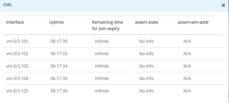
From the CLI:
admin@Branch1-Mpls-cli> show pim join extensive Tenant1-LAN-VR inet sg
S,G table
Group: 227.1.1.1
    Source: 172.16.1.1
    Upstream interface: dtvi-0/700 (Hub1)
    Upstream neighbor: 10.100.13.101
    Upstream state: Join to Source
    Uptime: 06:16:49
    Downstream neighbors:
        Interface: vni-0/3.101
            Uptime: 06:16:42
            Remaining time for join expiry: Infinite
            Assert state: No info
            Assert winner address: N/A
        Interface: vni-0/3.102
            Uptime: 06:16:45
            Remaining time for join expiry: Infinite
            Assert state: No info
            Assert winner address: N/A
        Interface: vni-0/3.103
            Uptime: 06:16:47
            Remaining time for join expiry: Infinite
            Assert state: No info
            Assert winner address: N/A
        Interface: vni-0/3.104
            Uptime: 06:16:43
            Remaining time for join expiry: Infinite
            Assert state: No info
            Assert winner address: N/A
        Interface: vni-0/3.105
            Uptime: 06:16:49
            Remaining time for join expiry: Infinite
            Assert state: No info
            Assert winner address: N/A
Display IGMP Group
From Director:
- Display the Services tab, as described in Monitor Hubs and Spokes, above.
- In the Networking pane, click PIM.
- Select the routing instance from the drop-down list. An additional drop-down list displays.
- Select Group from the second drop-down.

From the CLI:
admin@Branch1-Mpls-cli> show igmp group Tenant1-LAN-VR
routing-instance: Tenant1-LAN-VR

Interface   : vni-0/3.101

Group       : 227.1.1.1
            Group mode       :  Exclude
            Last reported by : 172.18.101.5
            Timeout :  00:03:27
            Type  :  Dynamic
 source : 0.0.0.0

Interface   : vni-0/3.102

Group       : 227.1.1.1
            Group mode       :  Exclude
            Last reported by : 172.18.102.5
            Timeout :  00:02:42
            Type  :  Dynamic
 source : 0.0.0.0

Interface   : vni-0/3.103

Group       : 227.1.1.1
            Group mode       :  Exclude
            Last reported by : 172.18.103.5
            Timeout :  00:03:00
            Type  :  Dynamic
 source : 0.0.0.0

Interface   : vni-0/3.104

Group       : 227.1.1.1
            Group mode       :  Exclude
            Last reported by : 172.18.104.5
            Timeout :  00:02:55
            Type  :  Dynamic
 source : 0.0.0.0

Interface   : vni-0/3.105

Group       : 227.1.1.1
            Group mode       :  Exclude
            Last reported by : 172.18.105.5
            Timeout :  00:03:09
            Type  :  Dynamic
 source : 0.0.0.0
Supported Software Information
Releases 20.2 and later support all content described in this article, except:
- Releases 21.2.1 and later adds the show route multicast-rpf CLI command.
- Releases 22.1.1 and later support VRRP-aware PIM.
- Releases 23.1.1 and later support group state limit, group state threshold, source group state limit, source group state threshold, register message filter, register send rate limit, register rate limit, neighbor filter, ASM filter, SSM filter options in the PIM virtual routing instance; IGMP join source and group filter and IGMP join group filter options in the IGMP virtual routing instance; and configure access list.
