Configure uCPE on a VOS Device
![]() For supported software information, click here.
For supported software information, click here.
The Versa Networks universal CPE (uCPE) solution is an open platform that allows you to deploy third-party vendor virtualized network functions (VNFs) along with the Versa Operating SystemTM (VOSTM) device in customer branches or hub sites.
When you configure service chaining with a VNF other than a Versa Network VNF, you cannot use forward error correction (FEC), packet replication, or per-packet load balancing.
Configure uCPE
The following are minimum requirements to enable a uCPE hypervisor on a VOS device:
- You can enable a uCPE hypervisor only on bare-metal devices and not on virtual machines (VMs). For information about the white-box appliances that support uCPE, see Versa SD-WAN White-Box Appliances.
- Minimum number of host CPUs: 8
- Minimum amount of host RAM: 16 GB
- Minimum host hard-disk capacity: 128 GB
Install Hypervisor Packages
Before you configure a uCPE on a VOS device, you must install hypervisor packages. Installing the hypervisor packages creates the OVS bridges and interfaces vni-0/300 through vni-0/307.
To install hypervisor packages:
- Ensure that all services on the CPE device are started.
-
Disable TACACS+ on the VOS devices. To do this, use either of the following methods:
-
Enter the delete system external-aaa command from the CLI on the VOS device.
-
In Appliance view, select Others > System > Appliance User Management > External AAA. Then, in the main pane, select the external authentication device and click Delete icon.

Once the uCPE is onboarded and confirmed, and the third-party VNF is up and functional, you can re-enable the External-AAA auth.
-
- On the CPE device, install the hypervisor packages.
admin@Branch-c2-uCPE-cli> request system hypervisor enable no-confirm
This command installs hypervisor packages and reboots the system. Note that you must install the hypervisor packages before you push the service chain template to the uCPE. Otherwise, the guest VNF cannot start.
- Verify that the hypervisor packages have been installed:
[admin@uCPE-4: ~] sudo virsh version
The following example output is for VOS devices running Ubuntu Trusty, Version 14.04:
[admin@Site1-CPE-1: ~] sudo virsh version
[sudo] password for admin:
Compiled against library: libvirt 4.0.0
Using library: libvirt 4.0.0
Using API: QEMU 4.0.0
Running hypervisor: QEMU 2.12.1
The following example output is for VOS devices running Ubuntu Bionic, Version 18.04:
[admin@uCPE-4: ~] sudo virsh version
[sudo] password for admin:
Compiled against library: libvirt 4.0.0
Using library: libvirt 4.0.0
Using API: QEMU 4.0.0
Running hypervisor: QEMU 2.11.1
-
Verify that the uCPE interfaces vni-0/300 through vni-0/307 have been created and mapped to the VOS switch:
admin@Branch-c2-uCPE-cli> show interfaces brief | grep UCPE
admin@Branch-c2-uCPE-cli> show interfaces statistics | grep UCPE
For example:
admin@SITE6-CPE2-cli> show interfaces statistics | grep UCPE | tab
vni-0/300    4       ServiceProvider-Control-VR  UCPE-MGMT1  0         0    0           0       0      0        0    0        0       0
vni-0/300.0  4       ServiceProvider-Control-VR  UCPE-MGMT1  0         0    0           0       0      0        0    0        0       0
vni-0/301    4       ServiceProvider-Control-VR  UCPE-MGMT2  0         0    0           0       0      0        0    0        0       0
vni-0/301.0  4       ServiceProvider-Control-VR  UCPE-MGMT2  0         0    0           0       0      0        0    0        0       0
vni-0/302    2       Customer1-LAN-VR            UCPE-PORT1  0         0    0           0       0      0        0    0        0       0
vni-0/302.0  2       Customer1-LAN-VR            UCPE-PORT1  0         0    0           0       0      0        0    0        0       0
vni-0/303    2       Customer1-LAN-VR            UCPE-PORT2  0         0    0           0       0      0        0    0        0       0
vni-0/303.0  2       Customer1-LAN-VR            UCPE-PORT2  0         0    0           0       0      0        0    0        0       0
vni-0/304    4       ServiceProvider-Control-VR  UCPE-PORT3  0         0    0           0       0      0        0    0        0       0
vni-0/304.0  4       ServiceProvider-Control-VR  UCPE-PORT3  0         0    0           0       0      0        0    0        0       0
vni-0/305    4       ServiceProvider-Control-VR  UCPE-PORT4  0         0    0           0       0      0        0    0        0       0
vni-0/305.0  4       ServiceProvider-Control-VR  UCPE-PORT4  0         0    0           0       0      0        0    0        0       0
vni-0/306    0                                   UCPE-PORT5  0         0    0           0       0      0        0    0        0       0
vni-0/307    0                                   UCPE-PORT6  0         0    0           0       0      0        0    0        0       0
vni-0/308    0                                   UCPE-PORT7  0         0    0           0       0      0        0    0        0       0
vni-0/309    0                                   UCPE-PORT8  0         0    0           0       0      0
Create a Vendor Catalog
To create a third-party VNF to the VOS vendor catalog:
- In Director view, select the Administration tab in the top menu bar.
- Select Inventory > uCPE > Vendor Catalog in the left menu bar.

- Click + Add to create a new vendor catalog. In the Image popup window, enter information for the following fields.

Field Description Vendor Catalog (Group of Fields) - Name
Enter a name for the uCPE that you are adding to the VOS device - Vendor
Select the supported vendor:
- Fortinet
- Riverbed
- Secui
- Palo Alto
- Microsoft
- Linux
- Replify
- Juniper
- Adtran
- Viasat
- Manage Vendors
Click to create a vendor. For more information, see Steps 3 through 5. - Product
Select the vendor's product. - Description
Enter a description for the uCPE. - Manage Products
Click to create a product for a vendor. For more information, see Step 6. - Version
Enter the uCPE version for the vendor. VNF Image (Group of Fields) - File Type
Select the VNF image file type. Currently, only qcow2 file type is supported. - Choose File
Select the qcow2 file to upload. - Compressed
Click if the file needs to be compressed. When selected, Director compresses and saves the file in the directory. When Director pushes the image to VOS, it transfers the compressed file into the CPE and decompresses the file before starting the uCPE VNF creation task. VNF Flavor (Group of Fields) - Memory
Enter the memory capacity of the product, in megabytes (MB). - Disk Size
Enter the disk size available in the product, in gigabytes (GB). - CPU Count
Enter the number of CPUs available in the product. - Secondary Disk Needed
Click if an additional disk is required, in gigabytes (GB).
- To create a new vendor, click Manage Vendors under Vendor. In the Manage Vendors popup window, click the
 icon.
icon.
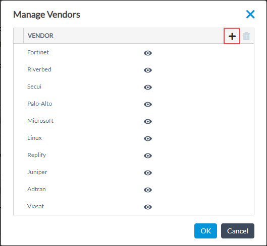
- In the Add New Vendors popup window, enter vendor name and click OK.

- To create a vendor product, click Manage Products under Product. In the Manage Products popup window, click the icon.

- In the Add New Product popup window, enter information for the following fields.
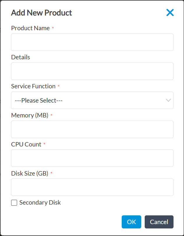
Field Description Product Name Enter a name for the product. Details Enter product details. Service Function Select the type of product: - Firewall
- Next-generation firewall
- WAN optimizer
- Others
Memory Enter the memory capacity of the product, in megabytes (MB). CPU Count Enter the number of CPUs available in the product. Disk Size Enter the disk size available in the product, in gigabytes (GB). Secondary Disk Click if an additional disk is required.
- Click OK.
Create a Cloud Profile
When a VM or guest VNF instantiates, you can push the configuration to the VM using a cloud profile. To create a cloud-init file, you upload a file that contains either user-specific or custom data that defines the common configuration tasks to perform when the guest VNF instantiates.
The qcow2 image brings up a guest VNF, and the cloud-init profile configures the VNF when it instantiates.
To create a cloud-init profile:
- Create a file that contains the user or custom data, and save the file on a local host.
- In Director view, select the Administration tab in the top menu bar.
- Select Inventory > uCPE > Cloud Profile in the left menu bar.
- Click the Add icon. In the Create Cloud Profile popup window, enter information for the following fields.
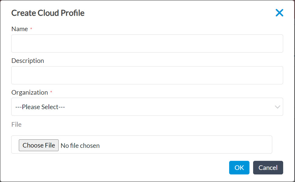
Field Description Name Enter a name for the cloud-init profile. Description Enter a text description for the cloud-init profile.
Organization Select the organization to which the profile belongs. File Select the file on your local system that contains the user or custom data to upload. - Click Ok. The main pane displays the cloud profile.
Create a Service-Chain Template
You use service-chain templates to onboard third-party VNFs into the uCPE device and then to create a workflow that chains the VNFs in an ordered fashion. You can select third-party VNFs from the catalog and chain them. This workflow creates a service-chain service template, which you can associate with a uCPE device template.
You create a service-chain template for a specific VNF. When you push this template to the device, the VNF on the uCPE device is instantiated. You can service-chain selected VNFs to multiple VRFs with different VLAN-based subinterfaces that you have created on both the VOS device and the VNF. You configure each VLAN data subinterface under the selected VRF.
To configure a VOS service-chain template:
- In Director view, select the Workflows tab in the top menu bar.
- Select Template > Service Chains in the left menu bar.
- Create the service chain:
- Click the
 Add icon to create a new service chain.
 - In the Service Chain popup window, select the General tab, and enter information for the following fields. Note that the screenshot here shows an example configuration for a device that is running multiple organizations, and it shows the provider organization and service-chain VNFs for the selected suborganization. (If a device is running only one organization, skip to Step 3d.)

Field Description
Service Chain Name (Required) Enter a name for the service chain. Model Details (Required) Select the device model. When you select a model, the Aggregated Resources group of fields display detail about the model's resources, such as CPU and memory capacity. The total resources available for the device model define the CPU and memory you can reserve for the guest VNFs. Aggregate Resources (Group of Fields) - Dedicated CPUs
Enter the number of CPUs to allocate as dedicated and shared. For example, if four CPUs are available, you can have two be dedicated CPUs and two be shared CPUs. If you change the number to three dedicated CPUs, the scroll bar for shared CPUs automatically adjusts to 1. - Memory
Enter the amount of memory to allocate. Organization Select the provider organization to which the service chain belongs. Suborganization (Table) If the device is running a service provider and multiple suborganizations, select the organizations to service-chain to the VNFs. Service Chain Select the guest VNF from the vendor catalog listed on the right side, and drag and drop it to the Versa FlexVNF (VOS device) box. This configuration chains the third-party VNF to the VOS device. - Select the VRF Management tab. The left column lists all the suborganizations that you selected in the General tab. For each suborganization, select at least one VRF per tenant, ensuring that the VLAN IDs are unique across all the VRFs. Service-chain workflows create subinterfaces based on the VLAN ID, and they associate these subinterfaces with the VRFs. For proper data-traffic communication, you must also configure the same set of subinterfaces in the VNFs. To add VRFs, click the
 Add icon and select the VRF from the drop-down. Then, continue with Step 5.

-
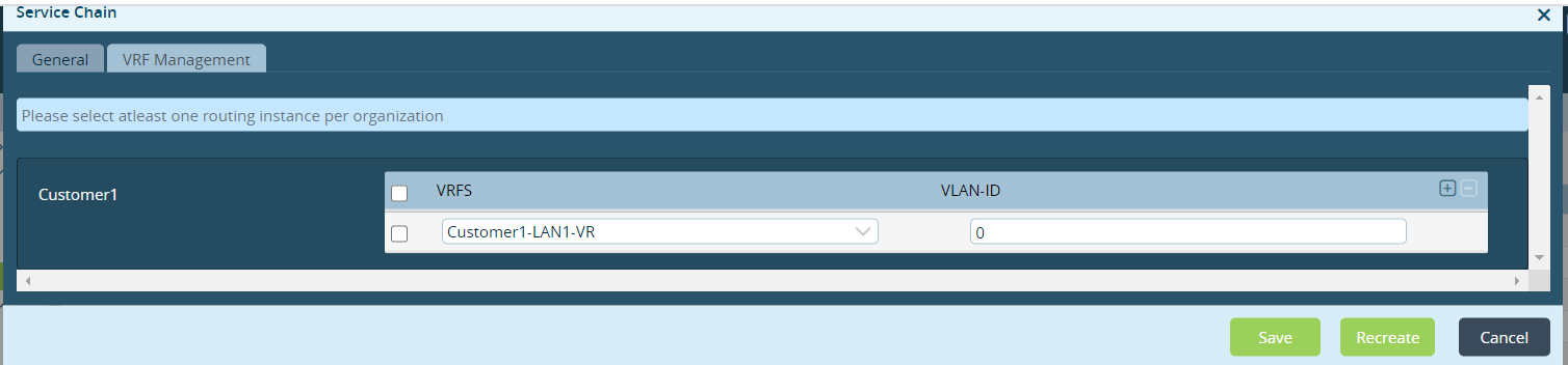
If the device is running only one organization, when you Select the General tab in the Service Chain popup window, a screen similar to the following displays. Select the organization in the Organization drop-down, and configure the fields, as described in Step 3b. However, do not select any suborganizations.

-
Select the VRF Management tab. Because the device is running only one organization, the left column lists only that organization. For the organization, select one or more VRFs, ensuring that each VRF has a unique VLAN IDs. Service-chain workflows create subinterfaces based on the VLAN ID, and they associate these subinterfaces with the VRFs. To add VRFs, click the
Add icon and select the VRF from the drop-down. Note, however, that in most cases, you can select only one VRF with VLAN ID 0, which is a non-tagged interface between the VOS device and the VNF.
- Click the
- Click the vendor box in the Service Chain popup window to modify the configuration of the guest VNF (uCPE) configuration. In the VNF Attributes popup window, enter information for the following fields.
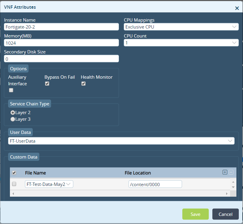
Field Description Instance Name Enter a name for the instance. Memory Enter the amount of memory to allocated to the VNF, in megabytes (MB). Secondary Disk Size Enter the size of the guest VNF's secondary disk, in megabytes (MB). CPU Mappings Select the CPU mapping category, which is used to determine the number of CPUs to allocate for the guest VNF from the available host CPU:
- Exclusive—Enter the number of CPUs to dedicate to the guest VNF.
- Manual—Enter the CPUs to allocate for the guest VNF. Here, you map the physical core to the VNF core.
- Shared—Enter the number of CPUs that the guest VNF can use. Also, if required, other guest VNFs can share the CPUs. This value is taken from the Shared CPU from the Aggregate Resources field.
CPU Count Select the number of CPUs. The number of available CPUs depends on the CPU mapping you select, and they are derived from the allocation done in Aggregate Resources field. Options (Group of Fields) - Auxiliary Interface
Click if the VNF requires secondary management interface. - Bypass On Fail
Click to monitor the data path in the VNF. If the VNF fails to process the traffic, data traffic bypasses the VNF when the VNF is in the shutdown state. - Health Monitor
Click to run ICMP ping to the management interface of the VNF. The VOS devices generates an alarm to state whether the guest VNF is up or down. Service Chain Type
Select the service chain type: - Layer 2
- Layer 3
User Data
Select the user data file that contains the configuration. The drop-down list displays the files that you uploaded when you created the cloud-init file. You can select the user data file only for a particular organization. Custom Data Select the custom data file that contains configuration details. The drop-down list displays the files that you uploaded when you created the cloud-init file.
The data in the file must be in a format that the VNF can interpret. For example, for Fortinet, you can use this setting to import the license key file. For Fortinet to interpret the license, the file format in the VNF must be specific for Fortinet.
- Click Save to update the guest VNF configuration.
-
Click Save and Deploy to commit the service chaining of the third-party VNFs on the VOS device.
For a single-tenant scenario, the service-chain template that you create is for a single customer tenant only. Here, it is the customer tenant that performs communication management, and the management plane for the VMs and the DHCP server belong to the customer tenant.
To configure a service-chain template for a single-tenant deployment, enter the following information in the fields in the Service Chain popup window, shown in Step 3d, above.
- In the Service Chain Name field, enter the name of the customer tenant service chain.
- In the Organization field, select the name of the customer tenant.
- Leave the Suborganization field empty.
- In the Routing Instance field, select the routing instance for the customer tenant's LAN VRs.
In a multitenant scenario, the service-chain template that you create belongs to the provider organization and is for the provider and the customer tenant. In this scenario, the provider performs communication management, and the management plane for the VMs and the DHCP server belong to the provider.
To configure a service-chain template for a multitenant deployment, enter the following information in the fields in the Service Chain popup window, shown in Step 3d, above.
- In the Service Chain Name field, enter the name of the provider service chain.
- In the Organization field, select the name of the provider.
- In the Suborganization field, select the customer tenant.
- In the Routing Instance field, select the routing instance for the customer tenant's LAN VRs.
Associate a Service-Chain Template with a Device Template
To chain a network service with the VOS device:
- In Director view, select the Configuration tab in the top menu bar.
- Select Devices > Device Groups in the horizontal menu bar.
- Select the name of a device group in the main pane. The Edit Device Group popup window displays, and the Post-Staging Template Association tab lists all the post-staging templates associated with the device group.

- Click the
 Edit Post Staging Template Association icon to edit the post-staging templates. The Edit Post-Staging Template Association popup window displays.

- Click the
 Add icon. In the Add Post-Stating Template Association popup window, enter information for the following fields.

Field Description Tenant Select the tenant. Category Select Service Chain. Templates Select the Template. - Click OK. The Edit Post-Staging Template Association popup window lists the new service template.

- Click OK.
Add a uCPE Device to a Device Template
- In Director view, select the Workflows tab in the top menu bar.
- Select Devices > Devices in the left menu bar.
- Click the Add icon to add a device to the device template. The Add Device popup window displays.
- In the Basic tab, enter information for the following fields.

Field Description Name Name of the device. Global Device ID Global device ID of the device. The next available global ID number is appears automatically. You can change this number up to 16383, as needed. Organization Organization to associate with the device Device Groups Name of the device group to add the device to. - In the Local Information tab, enter the address and geographical coordinates of the device.

- In the Bind Data tab, select the User Input tab.

- In the Post-Staging Template tab, select the bind data values.
- In the Service Template Variable tab, select the template from the Service Templates drop-down list. Then enter DHCP information for the device.
- Click Validate Template.
- Click Save to add the device to the device template, or click Deploy to add the device to the device template and to activate the device.
Onboard a uCPE using ZTP
To onboard a uCPE device, you use ZTP, as described in Use URL-Based ZTP To Activate a VOS Device. During the ZTP process, the Director node copies the user data or custom data files to the uCPE device if you configure these in the template.
After the uCPE device is up, the Controller sends the post-staging notification to Versa Director. Versa Director then checks whether the qcow2 software image file is present in the /home/versa/images directory on the uCPE device. If this file is not present, Versa Director copies the file to the uCPE device. It then issues the command to start the uCPE device.
Associate the Service-Chain Template with the uCPE
When you onboard the uCPE device using ZTP, no service-chain template is associated with the uCPE. To associate the service-chain template with the uCPE device:
- Create service-chain templates for specific VOS devices.
- Attach the service-chain template to the device group, and enter the bind-data in the device workflows.
- Associate the template with the device on the Commit popup window.
You can allocate dedicated CPU and memory resources to the VOS devices from the host resources. To do this, you must reboot the device before you bring up any VMs so that the aggregate VNF resources configuration can take effect. To reboot the device, click the Reboot option on the Commit popup window when you commit the service chain template to the device. If you do not select Reboot, the VOS device does not accept the service chain template configuration.

Verify the uCPE Configuration
To verify that the uCPE has been created on the VOS device, in Director view, select the Administration tab in the top menu bar and select Appliances in the left menu bar. The dashboard lists the devices configured on the VOS device. Check that the uCPE is listed.

Monitor Service-Chain Instances
To monitor service-chain instances from the Director GUI:
- In Director view, select the Monitor tab.
- Select Devices in the horizontal menu bar.
- Select a uCPE device in the main pane, and then click Services tab.
- In the Services box, select the SCI
 tab.
tab.
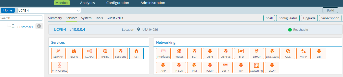
- Select Detail in the drop-down list to view detailed information about the configuration of the service-chain instances.

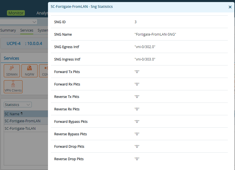
- Select Statistics from the drop-down list to view statistics about the data traffic on the service-chain instances.

- Click View to display details about the data statistics for an individual service-chain instance.

To monitor service-chain instances from the Director CLI:
-
View brief information about the status of the service-chain instances:
admin@uCPE-4-cli> show orgs org-services customer-name service-chain-instances brief
                              SNG                         SNGC          SESSION
SC NAME               SC ID   ID   SNG NAME               NAME  STATUS  COUNT
---------------------------------------------------------------------------------
SC-Fortigate-FromLAN  128511  0    default-sng            -     Up      -
                              3    Fortigate-FromLAN-SNG  -     Up      -
SC-Fortigate-ToLAN    128767  4    Fortigate-ToLAN-SNG    -     Up      -
                              0    default-sng            -     Up      -
-
View detailed information about the status of the service-chain instances, including the configuration of the bypass-on-fail option and the status of the egress and ingress monitors:
admin@uCPE-4-cli> show orgs org-services customer-name service-chain-instances detail SC-Fortigate-FromLAN
Service Chain Details:
Name                        - SC-Fortigate-FromLAN
ID                          - 128511
Total SNGs                  - 2
External SNGs               - 1

Service Node Group Details:
default-sng     [0]
   SNG Type                    - internal
   SNG Order                   - 1
   Cluster                     - -

Fortigate-FromLAN-SNG [3]
   SNG Type                    - sfc-unaware-service-function
   SNG Order                   - 2
   Cluster                     - -
   L2 Mode                     - true
   Bypass on Fail              - true
   Egress Monitor              - Up
   Egress Interface            - vni-0/302.0    [172.18.4.1]
   Ingress Monitor             - Up
   Ingress Interface           - vni-0/303.0    [172.18.4.2]
- View brief statistics about data traffic on the service-chain instances:
admin@uCPE-4-cli> show orgs org-services customer-name service-chain-instances stats brief
                              SNG                                                   FWD   FWD   REV   REV   FWD     REV     FWD    REV
SC NAME               SC ID   ID   SNG NAME               EGRESS       INGRESS      TX    RX    TX    RX    BYPASS  BYPASS  DROPS  DROPS
------------------------------------------------------------------------------------------------------------------------------------------
SC-Fortigate-FromLAN  128511  3    Fortigate-FromLAN-SNG  vni-0/302.0  vni-0/303.0  1061  1061  1061  1061  0       0       0      0
SC-Fortigate-ToLAN    128767  4    Fortigate-ToLAN-SNG    vni-0/303.0  vni-0/302.0  690   690   690   690   0       0       0      0
- View detailed statistics about data traffic for individual service-chain instances:
admin@uCPE-4-cli> show orgs org-services customer-name service-chain-instances stats detail
Service Chain Statistics:
Name                        - SC-Fortigate-FromLAN
ID                          - 128511
Total SNGs                  -
External SNGs               -

Service Node Group Statistics:
Fortigate-FromLAN-SNG [3]
   Forward         vni-0/302.0 ==> vni-0/303.0
   To VNF                           From VNF
   ------                           --------
   Tx Packets      - 1061           Rx Packets      - 1061
   Tx Bytes        - 89124          Rx Bytes        - 89124
   Bypass Packets  - 0
   Bypass Bytes    - 0
   Drop Packets    - 0
   Drop Bytes      - 0

   Reverse         vni-0/303.0 ==> vni-0/302.0
   To VNF                           From VNF
   ------                           --------
   Tx Packets      - 1061           Rx Packets      - 1061
   Tx Bytes        - 89124          Rx Bytes        - 89124
   Bypass Packets  - 0
   Bypass Bytes    - 0
   Drop Packets    - 0
   Drop Bytes      - 0
- Display statistics about traffic matching the service filter rules:
admin@uCPE-4-cli> show orgs org-services customer-name service-filters default-classifier
                                                                HIT
CLASSIFIER          RULE NAME                                  COUNT  LAST HIT
---------------------------------------------------------------------------------------
default-classifier  ToVM-Mgmt                                   6      00:00:06
                    FromVM-Mgmt                              7758      00:00:45
                    FromVM                                      0      -
                    ToVM                                        0      -
                    FromLAN-Customer1-LAN1-VR                  10      00:00:53
                    ToLAN-Customer1-LAN1-VR                     7      00:00:29
- Display brief flow-level service-chain statistics:
admin@uCPE-4-cli> show orgs org customer-name sessions brief

VSN  VSN  SESS                                SOURCE  DESTINATION
ID   VID  ID     SOURCE IP    DESTINATION IP  PORT    PORT         PROTOCOL  NATTED  SDWAN  APPLICATION
-----------------------------------------------------------------------------------------------------------
0    2    34982  10.0.0.4     10.1.128.1      1284    1234         6         No      No     -
0    2    36764  172.25.4.2   208.91.112.52   3187    53           17        No      No     dns/(predef)
0    2    36765  172.18.4.1   172.18.4.2      2696    2696         1         No      No     -
0    2    36792  192.168.4.3  192.168.3.1     6004    6004         1         No      Yes    icmp/(predef)
0    2    36793  172.25.4.2   208.91.112.220  3187    53           17        No      No     -
0    2    36795  10.0.254.52  10.0.255.255    137     137          17        No      No     nbns/(predef)
0    2    34992  192.168.3.3  192.168.4.3     27284   27284        1         No      Yes    icmp/(predef)
0    2    36794  10.0.199.36  10.0.255.255    138     138          17        No      No     smb/(predef)
- Display detailed flow-level service-chain statistics:
admin@uCPE-4-cli> show orgs org customer-name sessions extensive | select source-port 6004 | grep sng

sng-1 sng-name       Fortigate-FromLAN-SNG
sng-1 forward-tx-pkts 102
sng-1 forward-tx-bytes 8568
sng-1 forward-rx-pkts 102
sng-1 forward-rx-bytes 8568
sng-1 reverse-tx-pkts 102
sng-1 reverse-tx-bytes 8568
sng-1 reverse-rx-pkts 102
sng-1 reverse-rx-bytes 8568
sng-1 forward-bypass-pkts 0
sng-1 forward-bypass-bytes 0
sng-1 reverse-bypass-pkts 0
sng-1 reverse-bypass-bytes 0
Monitor the uCPE
To monitor the uCPEs on a VOS device:
- To view uCPE statistics, in Director view, select the Monitor tab in the top menu bar, and then select Organization > Devices > uCPE in the left menu bar.

- Add a static route for the VOS device management prefix on the Director node to provide HTTP/HTTPS/SSH access to the Director node so that it can access the VOS devices to gather the information to display on the Monitor screen. These static routes are similar to the static routes configured on the Director node for the VOS device overlay subnet with the same next hop. The connection from the Director node to the VOS management interface is as follows: Director-Southbound ► Controller-Northbound ► Overlay Connection to Branch-Control-VR ► VOS Management. For more information, see Configure Static Routes.
- To view detailed information about a uCPE, select the Guest VNFs tab in the horizontal menu. The main pane displays two graphs: CPU and memory usage, in 30-second intervals, and ingress and egress transmit and receive statistics, in 30-second intervals. From the Guest VNFs tab, you can access the guest VNF VMs using SSH, the console, or HTTP/HTTPS. To do so, click the field at the bottom of the screen. For console access, the Director node opens TCP port 6080, and for HTTP and HTTPS it opens port TCP 9090. If your deployment has a firewall in front of the Director node, ensure that these ports are open. For AWS, open these ports in the security group associated with the Director node's management interface.

- To shut down, reset, and reboot the uCPE, and to connect to third-party VNFs using SSH, the console, or HTTP, in Director view, select the Analytics tab from the top menu bar, and then select Dashboards > System > Guest VNF in the left menu bar.

- To check the status of the VNFs running on the device:
cli> show guest-vnfs virtual-machines info detail
For example:
admin@Branch-uCPE-cli> show guest-vnfs virtual-machines info detail

Virtual Machine            Adtran
   State                   running
   Uptime                  9w0d03h
   Creation Timestamp      2019-10-11 10:32:42.383208
   Management IP           172.25.1.5
   Management MAC          52:54:00:00:01:01
   Number of CPUs          2
   Memory                  2048
   VNC Port                5901
   Management Interface    vni-0/300.0
   Auxiliary Interface     n/a
   Left Interface          vni-0/302.0
   Right Interface         vni-0/303.0
   Primary Volume
     Disk Path             /home/versa/images/adtran.qcow2
     Disk Format           qcow2
   Secondary Volume
     Disk Path             n/a
     Disk Format           n/a
- To start a VM in case you need to intervene manually:
cli> request guest-vnfs virtual-machines vm-name start
For example:admin@uCPE-4-cli> request guest-vnfs virtual-machines vStream start status success result Start request sent
- To verify the status of the VM:
cli> request guest-vnfs virtual-machines vm-name start
- To shut down a VM in case you need to intervene manually:
cli> request guest-vnfs virtual-machines vm-name shutdown force
For example:admin@uCPE-4-cli> request guest-vnfs virtual-machines vStream shutdown force status success result Shutdown request sent
View the uCPE in Versa Analytics
To view uCPE information maintained on an Analytics node, in Director view, select the Analytics tab in the top menu bar, and then select Dashboards > System > Guest VNF.

Troubleshoot uCPE
You can use the following procedures to troubleshoot uCPE issues.
Start the Versa Virtualization Manager Service
If the versa-virtmgr service fails to start, do the following:
- Try to start the service individually. From the shell, issue the sudo initctl start versa-virtmgr command:
[admin@uCPE-4: ~] $ sudo initctl start versa-virtmgr
- Versa-virtmgr depends on the versa-virtlogd and versa-virtlockd services. Check the status of these services in the vsh status output. If the services fail to come up, start them manually by issuing the following commands:
[admin@uCPE-4: ~] $ sudo service virtlogd start
[admin@uCPE-4: ~] $ sudo service virtlockd start
- Start the versa-virtmgr service:
[admin@uCPE-4: ~] $ sudo initctl start versa-virtmgr
Increase the VM Disk Size
Before you can increase the VM disk size, make sure you have administrator credentials with SSH and CLI access to the uCPE.
- View the running VMs. From the shell, issue the sudo virsh list command.
[admin@uCPE-3:~] $ sudo virsh list
Id    Name                           State
----------------------------------------------------
4     K8-Worker-1                    running
5     Windows                        running
- You must shut down the VM before resizing. From the CLI, issue the request guest-vnfs virtual-machines <vn-name> shutdown command for the target VM. In the example below, the VM is KB-Worker-1.
admin@uCPE-3-cli> request guest-vnfs virtual-machines K8-Worker-1 shutdown
status success
- Get the disk image path. From the shell, issue the sudo virsh domblklist <vm-name> command. The main OS disk is vda.
[admin@UCPE-3: ~] $ sudo virsh domblklist K8-Worker-1
Target     Source
------------------------------------------------
vda        /var/lib/libvirt/images/19d9433c-f6f4-11f0-af9e-ac43308e655e
vdc        /var/lib/libvirt/images/K8-Worker-1-seed.iso
- Check the current disk size. Issue the sudo qemu-img info <path> command using the path from the previous step. The "virtual size" field shows the current allocated disk size. In the example below, the current virtual size is 10 GB.
[admin@UCPE-3: ~] $ sudo qemu-img info /var/lib/libvirt/images/19d9433c-f6f4-11f0-af9e-ac43308e655e
image: /var/lib/libvirt/images/19d9433c-f6f4-11f0-af9e-ac43308e655e
file format: qcow2
virtual size: 10G (10737418240 bytes)
disk size: 8.3G
cluster_size: 65536
- Increase the disk size. From the CLI, issue the request guest-vnfs virtual-machines <vm-name> increase-disk size <size> command. The size argument is in gigabytes (GB) and is added to the current virtual size. The range is 1 through 255 GB.
admin@UCPE-3-cli> request guest-vnfs virtual-machines K8-Worker-1 increase-disk size 2
status success
result Disk-size increase request sent
- To verify the new disk size, issue the sudo qemu-img info <path> shell command again. In the example below, the disk size is 12 GB, an increase of 2 GB over the original 10 GB. The disk size reflects actual host usage and does not change until the guest writes data.
[admin@UCPE-3: ~] $ sudo qemu-img info /var/lib/libvirt/images/19d9433c-f6f4-11f0-af9e-ac43308e655e
image: /var/lib/libvirt/images/19d9433c-f6f4-11f0-af9e-ac43308e655e
file format: qcow2
virtual size: 12G (12884901888 bytes)
disk size: 8.3G
cluster_size: 65536
- Start the VM. From the CLI, issue the request guest-vnfs virtual -machines <vn-name> start command.
admin@UCPE-3-cli> request guest-vnfs virtual-machines K8-Worker-1 start
status success
result Start request sent
After boot, extend the partition and filesystem inside the guest to use the extra space. The underlying image is larger but the guest partition table is unchanged.
Alarms Generated for uCPE
If you enable the health monitor when you configure the VMs, alarms are generated for the management reachability of the running VNFs when the management interface is not reachable. To view the alarms:
cli> show alarms last-n 205 | grep virtmgr
virtmgr    guestVnfDown   2018-05-02T15:45:42-0 Provider: Guest VNF Adtran is down. Management interface probe failure
virtmgr    guestVnfUp     2018-05-02T15:47:12-0 Provider: Guest VNF Adtran is up. Management interface probe success
Alarms are generated for the data-path reachability between Versa VNF and the third-party VNF. Monitoring is triggered only if bypass-on-fail is generated under the org-level service-chain-instance. To view the alarms:
cli> show alarms last-n 200 | grep sfc
sfc    sngDown           2018-04-23T17:25:58-0 Customer2: Service Node Group Fortios-FromLAN-SNG is down. Health monitor failure
sfc    sngUp             2018-04-20T15:34:31-0 Customer2: Service Node Group Fortios-FromLAN-SNG is up. Health monitor success
Supported Software Information
Releases 20.2 and later support all content described in this article, except:
- For Releases 21.1.1 and later, you can configure multiple tenants and multiple VRFs in a service chain template.
Additional Information
Configure Service Chains
Solution Use Cases
Versa SD-WAN White-Box Appliances