Configure EIP-Based Microsegmentation for SD-LAN
![]() For supported software information, click here.
For supported software information, click here.
Microsegmentation is a network security strategy that allows you to divide a network into smaller, isolated segments, called microsegments. You create each microsegment around a specific set of resources or services, and you define access controls and configure security policies that are specific for the resources and services in the microsegment. Traditional network security models primarily rely on securing the network perimeter, using methods such as firewalls to protect the entire network. With microsegmentation, you can apply security controls at a more granular level, providing an additional layer of security. You can create security zones in your network and apply security policies to each microsegment to provide enhanced security by restricting lateral movement within the network.
With Versa Operating SystemTM (VOSTM) microsegmentation, you can place user client devices and clientless (headless) IoT devices into microsegments. For more information, see Configure Microsegmentation.
If the security posture of a device does not meet the standards, the VOS software moves it from a microsegment that allows access to sensitive applications and data to a microsegment with more restrictive resource access policies.
Each VOS switch or access point in the LAN that combines Layer 2 or Layer 3 switching with an integrated next-generation firewall (NGFW) can handle the security requirements of the traffic that enters that device. This on-premise, ZTNA-distributed firewall-on-a-switch architecture scales well, and it reduces traffic latency by eliminating traffic hair-pinning to apply security services on a cloud security point of presence (PoP).
This article describes how to configure microsegmentation using endpoint information profiles (EIPs) for SD-LAN. You can configure EIP-based microsegmentation on Versa Cloud Services Gateway (CSG) and Versa Cloud Services Switch (CSX) platforms to connect a Versa SASE client in gateway-assisted trusted-network mode.
The configuration example for EIP-based microsegmentation in this article describes the following configuration flow:
- Configure a paired tunnel virtual interface (TVI), and add an interface to a virtual router (VR).
- Configure a virtual router to detect trusted networks, and configure the paired TVI to the virtual router.
- Add the TVI interface to the tenant organization.
- Add the paired TVI interface to the LAN network and LAN virtual router (LAN-VR).
- Add a static route on the tenant LAN-VR to the SASE gateway IP address through the paired TVI interface.
- Add client-facing interfaces and paired TVI interfaces to LAN zones.
- Configure zones and associate interfaces and LAN zones.
- Configure NGFW rules to allow traffic from the LAN zones.
- Configure captive portal to associate the virtual router routing instance used for detecting trusted networks.
- Configure a DNS proxy with a redirection rule that responds to a domain name with a static IP address.
- Configure authentication profiles and users in the LDAP, local, or Security Assertion Markup Language (SAML) database.
- Configure EIP objects and associate them with custom EIP profiles, and configure microsegmentation policies to match the EIP profiles.
- Configure the SASE gateway for trusted-network mode.
Before You Begin
For microsegmentation to work on CSG and CSX devices, you must select a scaled ZTNA profile as the NPU predefined switch profile.
To select a scaled ZTNA profile:
- In Director view:
- Select the Administration tab in the top menu bar.
- Select Appliances in the left menu bar.
- Select an appliance in the main pane. The view changes to Appliance view.
- Select the Configuration tab in the top menu bar.
- Select Others > System > Configuration > Configuration in the left menu bar. The main pane displays panes related to system settings.

- In the Platform pane, click
Edit. The Edit Platform popup window displays.

- Select the NPU tab, and then select the Switch Profile tab.
- Click the Predefined field, and then select a scaled ZTNA profile. The profile can be either scaled-ztna-default (as shown here) or scaled-ztna-routes.
- Restart the device for the profile selection to take effect.
- Click OK.
Configure Paired Tunnel Interfaces
You configure two TVI interfaces for routing secure access traffic that reaches a captive portal through a client that is connected to trusted branch locations.
To configure the TVI interfaces:
- In Director view:
- Select the Configuration tab in the top menu bar.
- Select Appliances in the left menu bar.
- Select an appliance in the main pane. The view changes to Appliance view.
- Select the Configuration tab in the top menu bar.
- Select Networking > Interfaces in the left menu bar.

- Select the Tunnel tab in the horizontal menu bar.
- Click the
 Add icon. In the Add Tunnel Interface popup window, select the Tunnel tab, and then enter information for the following fields.

- In the Interface fields, enter the port and slot numbers for the TVI interface (here, 0 and 101).
- In the Mode field, select IPsec.
- In the Tunnel Type field, select Paired.
- In the Paired Interface field, enter the port and slot number of the paired interface (here, 0 and 100).
- In the Subinterfaces section, click the
 Add icon. The Add Subinterface popup window displays.
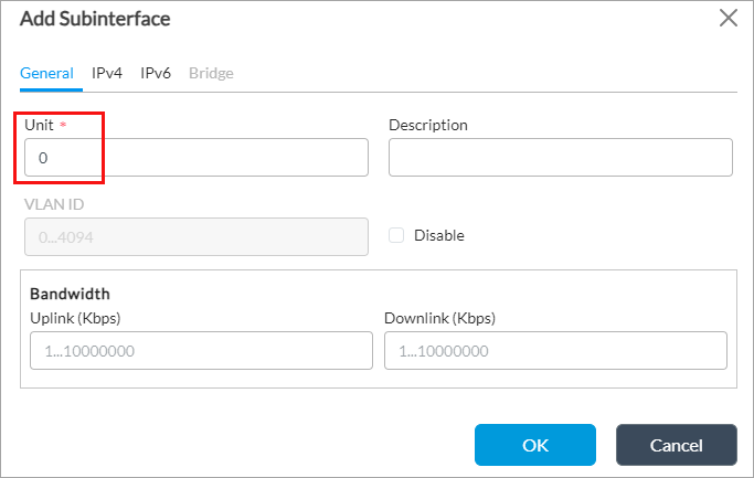
- Select the General tab, and then, in the Unit field, enter a unit number (here, 0).
- Select the IPv4 tab, and then enter the IP address prefix and prefix length of the static IP addresses you want to use (here, 100.100.100.1/32 and 169.254.100.3/31).

- For the paired TVI interface (here, tvi-0/100), add the static IP address (here, 169.254.100.2/31).
- For information about configuring other parameters, see Configure Tunnel Interfaces in Configure Interfaces.
- Click OK.
Configure a Virtual Router To Detect Trusted Networks
- In Director view:
- Select the Administration tab in the top menu bar.
- Select Appliances in the left menu bar.
- Select an appliance in the main pane. The view changes to Appliance view.
- Select the Configuration tab in the top menu bar.
- Select Networking > Virtual Routers in the left menu bar.
- Click the
 Add icon. The Configure Virtual Router popup window displays.

- Select the Virtual Router Details tab.
- In the Instance Name field, enter a name for the virtual router (here, Trusted-Network-Detection-CP-VR).
- In the Instance Type field, select Virtual Routing Instance.
- In the Interfaces/Networks field, click the
 Add icon and then select the first paired interface (here, tvi-0/101.0) that you added in Configure Paired Tunnel Interfaces, above.
 - For information about configuring other parameters, see Set Up a Virtual Router.
- Select the Static Routing tab, and then select the IPv4/v6 Unicast tab.

- Click the
 Add icon. The Add IPv4/v6 Unicast popup window displays.

- In the Destination field, enter the destination IP address or network (here, 0.0.0.0/0).
- In the Preference field, enter 1 as the administrative distance (AD), or route preference, value of the static route.
- In the Interface field in the Action section, select the first TVI interface (here, tvi-0/101.0) that you added in Configure Paired Tunnel Interfaces, above.
- In the Next-Hop IP Address field, enter the static IP address that you added for the paired TVI interface (here, 169.254.100.2) in Configure Paired Tunnel Interfaces, above.
- For information about configuring other parameters, see Configure Static Routes.
- Click OK.
Add a TVI Interface and Routing Instance to the Tenant Organization
- In Director view:
- Select the Administration tab in the top menu bar.
- Select Appliances in the left menu bar.
- Select a device name in the main panel. The view changes to Appliance view.
- Select an organization.
- Select the Configuration tab in the top menu bar.
- Select Others > Organization > Limits in the left menu bar. The main pane displays the organizations associated with the device.
- Click an organization name in the main pane (here, Tenant1). The Edit Organization Limit popup window displays.

- Select the Traffic Identification tab.
- In the Interfaces field, click the
 Add icon, and then select the first interface (here, tvi-0/101.0) that you added in Configure Paired Tunnel Interfaces, above.
 - Select the Resources tab.

- In the Available Routing Instances and Owned Routing Instances fields, click the
 Add icon, and then select the virtual routing instance (here, Trusted-Network-Detection-CP-VR) that you added in Configure a Virtual Router To Detect Trusted Networks, above.
 - For information about configuring other parameters, see Configure Organization Limits.
- Click OK.
Add Paired TVI Interfaces to the LAN Network and LAN Virtual Router
The paired TVI interfaces are used to connect to virtual routers. You add one TVI interface to connect to the LAN-VR network and a second TVI interface to connect to the virtual router that is used to detect trusted networks.
To add the paired TVI interface (here, tvi-0/100) to the LAN-VR network:
- In the Director view:
- Select the Administration tab in the top menu bar.
- Select Appliances in the left menu bar.
- Select a device name in the main panel. The view changes to Appliance view.
- Select the Configuration tab in the top menu bar.
- Select Networking > Networks in the left menu bar.
- Select the LAN network (here, LAN-1) for which you want to add the TVI interface. The Edit Network window displays.

- In the Interfaces field, click the
 Add icon, and then select the first TVI interface (here, tvi-0/100.0) that you configured in Configure Paired Tunnel Interfaces, above.
To add the TVI interface (here, tvi-0/101) to the tenant LAN-VR that is used to detect trusted networks:
- In Director view:
- Select the Administration tab in the top menu bar.
- Select Appliances in the left menu bar.
- Select an appliance in the main pane. The view changes to Appliance view.
- Select the Configuration tab in the top menu bar.
- Select Networking > Virtual Routers in the left menu bar.
- Select the virtual router (here, Tenant-1-LAN-VR) for which you want to associate the TVI interface. The Edit VR window displays.
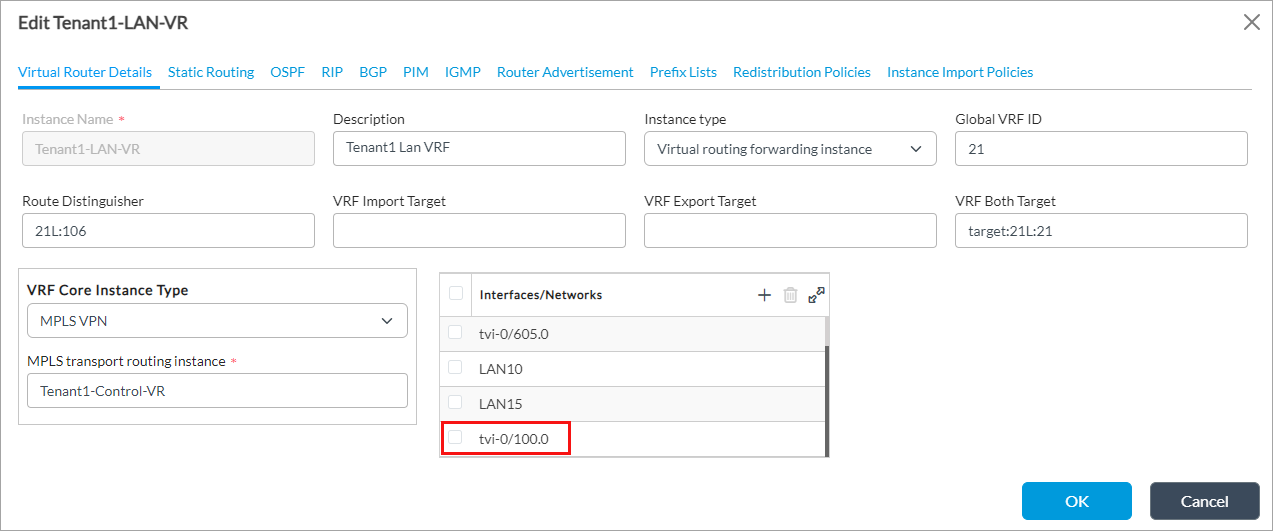
- In the Interfaces/Networks field, click the
 Add icon, and then select the first TVI interface (here, tvi-0/100.0) that you configured in Configure Paired Tunnel Interfaces, above.
 - Click OK.
Add a Static Route to the SASE Gateway in the LAN VR
You add a static route to the SASE gateway in the LAN virtual router (here, Tenant1-LAN-VR) through the paired TVI interface.
To add a static route:
- In Director view:
- Select the Administration tab in the top menu bar.
- Select Appliances in the left menu bar.
- Select an appliance in the main pane. The view changes to Appliance view.
- Select the Configuration tab in the top menu bar.
- Select Networking > Virtual Routers in the left menu bar
- Click the
 Add icon. The Configure Virtual Router popup window displays.
 - Select the Static Routing tab, and then select the IPv4/v6 Unicast tab.
- Click the
 Add icon. The Add IPv4/v6 Unicast popup window displays.
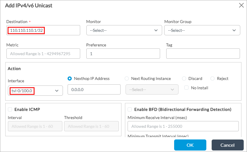
- In the Destination field, enter the SASE gateway destination IP address (here, 110.110.110.1/32).
- In the Interface field in the Action section, select the paired TVI interface (here, tvi-0/100.0) that you added in Configure Paired Tunnel Interfaces, above.
- Click OK.
Add Enterprise Names, a Gateway FQDN, and Services to the Tenant Organization
You add an enterprise name; a gateway FQDN; and CGNAT, NGFW, SD-WAN, and secure access services to the tenant organization.
To update the tenant organization:
- In Director view:
- Select the Administration tab in the top menu bar.
- Select Appliances in the left menu bar.
- Select a device name in the main panel. The view changes to Appliance view.
- Select an organization.
- Select the Configuration tab in the top menu bar.
- Select Others > Organization > Limits in the left menu bar. The main pane displays the organizations associated with the device.
- Click an organization name in the main pane (here, Tenant1). The Edit Organization Limit popup window displays.

- Select the General tab.
- In the Enterprise Names field, click the
 Add icon, and then enter the name of an enterprise that is in the organization (here, sandbox).
 - In the Gateway FQDN field, click the
 Add icon, and then enter the fully qualified domain name (FQDN) of the organization's gateway (here, blr-sandbox.versa.com).
 - To add services to the organization, select the Services tab. Note that before you can add a service, you must enable that service on the VOS device. For example, to add NGFW, see Enable NGFW in Configure NGFW.

- In the Services field, click the
 Add icon, and then select cgnat, nextgen-firewall, sdwan, and secure-access.
 - For information about configuring other parameters, see Configure Organization Limits.
- Click OK.
Configure Zones To Add Client-Facing Interfaces and Pair Tunnel Interfaces
You configure zones and associate them with interfaces and LAN networks. You can then configure NGFW rules that allow traffic from these zones.
To configure a zone and add paired TVI interfaces to them:
- In Director view:
- Select the Configuration tab in the top menu bar.
- Select Devices > Devices in the horizontal menu bar.
- Select an organization in the left menu bar.
- Select a Controller in the main pane. The view changes to Appliance view.
- Select the Configuration tab in the top menu bar.
- Select Networking > Zones in the left menu bar. The table in the main pane displays the configured zones.
- Click the
 Add icon. The Add Zone popup window displays.

- Add a name for the zone (here, T1-REMOTE-CPVR-VR).
- Select Interface and Networks.
- In the Interfaces field, click the
 Add icon, and then select the paired TVI interface (here, tvi-0/101.0) that you added in Configure Paired Tunnel Interfaces, above.
 - For information about configuring other parameters, see Configure Zones.
- Click OK.
To configure a client-facing zone and add LAN Ethernet interfaces to the zone:
- In the Add Zone popup window, enter information for the following fields.
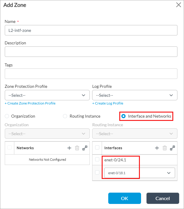
- Enter a name for the zone (here, L2-intf-zone).
- Select Interface and Networks.
- In the Interfaces field, click the
 Add icon, and then select the LAN Ethernet interfaces (here, enet-0/18.1 and enet-0/24.1) you want to associate with the zone. For more information, see Configure LAN Ethernet Interfaces.
 - Click OK.
To configure a zone associated with your LAN network:
- In the Add Zone popup window, enter information for the following fields.

- Enter a name for the zone (here, Intf-LAN-Zone).
- Select Interface and Networks.
- In the Networks field, click the
 Add icon, and then select the LAN (here, LAN1) you want to associate with the zone.
 - Click OK.
Configure NGFW Rules To Allow Traffic from LAN Zones
To configure NGFW rules:
- In Director view:
- Select the Administration tab in the top menu bar.
- Select Appliance in the left menu bar.
- Select the device in the main pane. The view changes to Appliance view.
- Select the Configuration tab in the top menu bar.
- Select Services > Next-Gen Firewall > Security > Policies in the left menu bar, and then select the Rules tab.
- Click the Add icon to define rules for the policy. The Add Rule popup window displays.

- Select the General tab, and then enter a name (here, LAN-Zones) for the rule in the Name field.
- Select the Source tab.

- In the Source Zone field, click the
 Add icon, and then select the zones Intf-LAN-Zone, L2-intf-zone, and T1-REMOTE-CPVR-VR that you configured in Configure Zones To Add Client-Facing Interfaces and Pair Tunnel Interfaces, above.
 - For information about configuring other parameters, see Configure NGFW.
- Click OK.
Configure Captive Portal To Associate a Routing Instance
To modify the captive portal settings to add the routing instance that you configured for detecting trusted networks:
- In Director view:
- Select the Administration tab in the top menu bar.
- Select Appliances in the left menu bar.
- Select a device name in the main panel. The view changes to Appliance view.
- Select the Configuration tab in the top menu bar.
- Select Services > Captive Portal in the left menu bar. The dashboard displays the Captive Portal Settings pane.
- Click the
 Edit icon. The Edit Captive Portal Settings popup window displays.
 - Select the General tab.
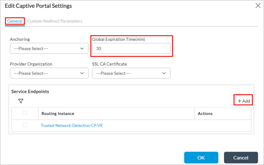
- In the Global Expiration Time field, enter how often users are redirected to the captive portal, in minutes. The first time a user enters a URL and is redirected to a captive portal page, the VOS device creates a cache entry. This cache entry expires after the global expiration time. Between the first time the user is redirected to the captive portal page and the expiration time, the captive portal action is not enforced and the user can go to the URL directly, without first seeing the captive portal page. The range is 1 through 65535 minutes, and the default is 30 minutes.
- In the Service Endpoints section, click the
 Add icon to add a service endpoint. The Service Endpoint popup window displays.

- In the Routing Instance field, select the routing instance (here, Trusted-Network-Detection-CP-VR) that you configured in Configure a Virtual Router To Detect Trusted Networks, above.
- In the HTTP Port field, enter the number (here, 80) of the HTTP port to use to redirect captive portal pages over HTTP.
- In the HTTPS Port field, enter the number (here, 443) of the HTTPS port to use to redirect captive portal pages over HTTPS.
- In the IP Address field, click the Add icon to add a service endpoint IP address (here, 110.110.110.1). Any traffic destined to this IP address is serviced by the captive portal.
- In the Server group of fields, for URL, enter the captive portal server URL that is used to redirect traffic when any captive portal action is applied (here, .*.versa.com). This URL resolves to one of the IP address in the IP address list.
- In the Certificate field, select the certificate to use for captive portal over SSL (here, RAS-Cert.crt).
- For information about configuring other parameters, see Modify Captive Portal Settings in Configure URL Filtering.
- Click OK.
Configure DNS Proxy
You configure DNS proxy with a redirection rule to respond to a domain name with a static IP address.
To configure a DNS proxy rule:
- In Director view:
- Select the Configuration tab in the top menu bar
- Select Devices > Devices in the horizontal bar.
- Select an organization in the left menu bar.
- Select the device in the main pane. The view changes to Appliance view.
- Select the Configuration tab in the top menu bar.
- Select Networking > DNS > Policies in the left menu bar.
- Select the Rules tab in the horizontal menu.
- Click Add or select an existing rule. The Add/Edit Redirection Rules popup window displays.
- Select the General tab, and then enter a name for the rule (here, DNS-resolv-GW).

- Select the DNS Headers Match tab.
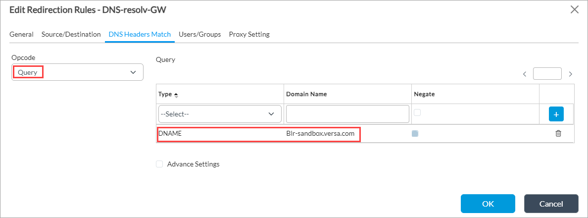
- In the Opcode field, select Query as the DNS header operation code.
- In the Query section, select DNAME in the Type field.
- In the Domain Name field, enter a domain name (here, Blr-sandbox.versa.com).
- Select the Users/Groups tab, and then in the Match Users field, select Any.

- Select the Proxy Setting tab.

- In the Actions section, click Server Setting.
- In the Server Setting section, click the
 Add icon, and then enter the IP address of the server (here, 100.100.100.1). This address maps the host that the SASE client uses to connect to the gateway to the gateway server.
 - For information about configuring other parameters, see Configure DNS Redirection Rules.
- Click OK.
Configure Authentication Profiles and Users in a Database
You configure authentication profiles and use them to identify users that use Versa SASE client to connect to the SASE gateway. You configure these users or user groups using an external, an LDAP, a local, or a SAML database, or any other database.
The following example shows how to use a local database to authenticate users. For this, you do the following:
- Configure the local authentication method.
- Configure an authentication profile, and then associate it with the local authentication method.
- Add local database users.
- Add the authenticator profile for local database users.
Configure an Authentication Method
- In Director view:
- Select the Administration tab in the top menu bar.
- Select Appliances in the left menu bar.
- Select a device name in the main panel. The view changes to Appliance view.
- Select the Configuration tab in the top menu bar.
- Select Object and Connectors > Connectors > Users/Groups > Authentication Methods in the left menu bar.
- Click the
 Add icon. The Add Authentication Methods popup window displays.

- In the Name field, enter a name for the authentication method (here, local-auth).
- In the Authentication Method field, select Local Profile.
- Click OK.
For more information, see Configure an Authentication Method.
Configure an Authentication Profile
- In Director view:
- Select the Administration tab in the top menu bar.
- Select Appliances in the left menu bar.
- Select a device name in the main panel. The view changes to Appliance view.
- Select the Configuration tab in the top menu bar.
- Select Object and Connectors > Connectors > Users/Groups > Authentication Profiles in the left menu bar.
- Click the
 Add icon. The Add Authentication Profile popup window displays.
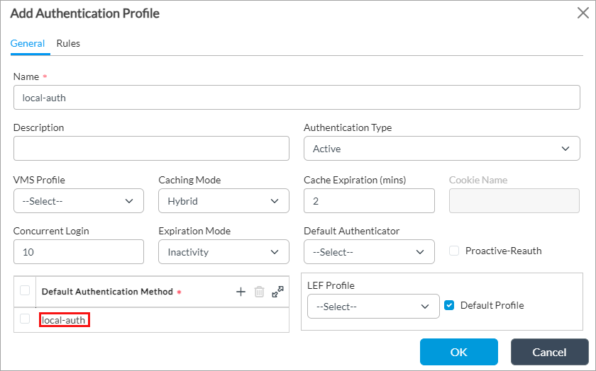
- Select the General tab.
- In the Name field, enter a name for the authentication profile (here, local-auth).
- In the Default Authentication Method field, click the
 Add icon, and then select the authentication method that you configured in Configure an Authentication Method, above (here, local-auth).
 - For information about configuring other parameters, see Configure an Authentication Profile.
- Click OK.
Configure Local Database Users
To configure local database users, see Configure Local Database Users.
Configure an Authenticator Profile
Before you configure an authenticator profile, ensure that SMTP server settings are enabled, to support two-factor authentication using a one-time password (OTP). For more information about receiving an OTP through email, see Configure SMTP Server Settings.
To configure an authenticator profile:
- In Director view:
- Select the Administration tab in the top menu bar.
- Select Appliances in the left menu bar.
- Select a device name in the main panel. The view changes to Appliance view.
- Select the Configuration tab in the top menu bar.
- Select Objects & Connectors > Connectors > Users/Groups > Authenticator Profiles in the left menu bar.
- Click the
 Add icon. The Add Authenticator Profiles popup window displays.
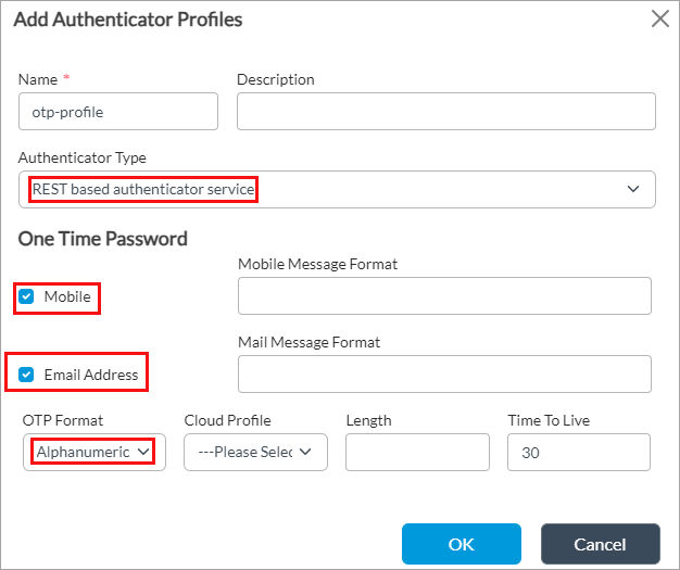
- In the Name field, enter a name for the authenticator profile (here, otp-profile).
- In the One-Time Password select, click Mobile and Email Address.
- In the OTP Format field, select Alphanumeric.
- For information about configuring other parameters, see Configure an Authenticator Profile.
- Click OK.
Configure EIP Objects and Profiles
You configure EIP objects and EIP profiles, and then you associate them with a microsegmentation policy.
Configure EIP Objects
In this example, we configure Windows firewall-based EIP objects.
To configure EIP objects:
- In Director view:
- Select the Configuration tab in the top menu bar.
- Select Templates > Device Templates in the horizontal menu bar.
- Select an organization in the left menu bar.
- Select a template in the main pane. The view changes to Appliance view.
- Select the Configuration tab in the top menu bar.
- Select Objects & Connectors > Objects > Custom Objects > EIP Objects in the left menu bar.
- Click the
 Add icon. The Add EIP Objects popup window displays.

- In the Name field, enter a name for the EIP object (here, fullycomplaintwindows).
- In the Category field, select Firewall.
- In the Installed and Running fields, click True.
- In the Vendor field, select the vendor (here, Microsoft Corporation).
- In the Product field, select a product from the vendor you select (here, Windows Firewall).
- Click OK.
- Add a second EIP object (here, Partialcompliantwindows) with the values displayed in the following screenshot.

- Click OK.
Configure EIP Profiles
To configure an EIP agent profile:
- In Director view:
- Select the Configuration tab in the top menu bar.
- Select Templates > Device Templates in the horizontal menu bar.
- Select an organization in the left menu bar.
- Select a template in the main pane. The view changes to Appliance view.
- Select the Configuration tab in the top menu bar.
- Select Objects and Connectors > Objects > Custom Objects > SASE Client > EIP Agent Profiles in the left menu bar.
- Click the
 Add icon. The Add EIP Profiles popup window displays.

- In the Name field, enter a name for the EIP profile (here, Partialcompliant).
- Click the
 Add icon to add a rule for the profile. The Add Rules popup window displays.
 - Select the General tab, and then enter a name for the rule.

- Select the Match tab.

- In the Match Categories section, click the
 Add icon. The Add Rules Add Match Category popup window displays.

- In the Category field, select Firewall.
- In the User-Defined EIP Objects field, click the
 Add icon, and then elect the EIP object that you configured in Configure EIP Objects, above.
 - Click OK.
- Repeat Steps 4 through 13 to create another EIP profile (here, the name is VSA-client, and fullycomplaintwindows is the EIP object associated with the rule match category).
Configure a SASE Gateway for Gateway–Trusted Network Mode
If you enable the detection of trusted networks for a SASE gateway, when the client attempts to connect to the gateway, you can configure the gateway so that informs the client that it is connected to a trusted network so that the client can then bypass the tunnel.
The following sections describe a configuration example to enable a SASE gateway for detecting trusted networks.
Configure a DNS Resolver
- In Director view:
- Select the Configuration tab in the top menu bar.
- Select Templates > Device Templates in the horizontal menu bar.
- Select an organization in the left menu bar.
- Select a template in the main pane. The view changes to Appliance view.
- Select the Configuration tab in the top menu bar.
- Select Services > Secure Access > Portal> DNS Resolvers in the left menu bar.
- Click the
 Add icon. The Add DNS Resolver popup window displays.

- In the Name field, enter a name for the DNS resolver (here, versa-networks.com).
- In the Name Server field, enter the DNS name IP address (here, 10.48.0.99) and click the
 Add icon.
 - In the Domain field, enter the name of the domain in which the DNS resolver is located (here, versa-networks.com).
- Click OK.
Configure a Secure Access Gateway Server
- In Director view:
- Select the Configuration tab in the top menu bar.
- Select Templates > Device Templates in the horizontal menu bar.
- Select an organization in the left menu bar.
- Select a template in the main pane. The view changes to Appliance view.
- Select the Configuration tab in the top menu bar.
- Select Services > Secure Access > Portal > Gateways in the left menu bar.
- Click the
 Add icon. The Add Profiles popup window displays.

- Select the General tab.
- In the Name field, enter a for the gateway profile (here, sw2-gateway1).
- Ensure that Allow Delete by App is not enabled. When it is enabled, gateways can be deleted on the secure access client.
- Click Display VPN Profile in OS to display configured VPN profiles in the native user device's operating system.
- In the Hosts field, enter the IP address or FQDN of the host that the SASE client uses to connect to the gateway and click the
 Add icon to add (here, Blr-sandbox.versa.com).
 - In the Priority field, enter a value to set the order in which the server is listed on the SASE client (here, 100).
- In the IPsec Profile ID field, enter the identifier of the IPsec profile of the secure access server profile (here, force_tunnelv2).
- In the CA Certificate field, select the CA certificate for the captive portal certificate (here, RAS-CA.crt).
- Select the Traffic Steering tab.

- Select the lower Traffic Steering tab.
- Click Split Tunnel.
- Optionally, in the Routes field, select the secure access routes, and then click the
 Add icon. For more information, see Configure Secure Access Routes.
 - In the DNS Resolver field, select the DNS resolver that you configured in Configure a DNS Resolver, above, (here, versa-networks.com), and then click the
 Add icon.
 - For information about configuring other parameters, see Configure Secure Access Servers in Configure Versa Secure Access Service.
- Click OK.
Configure the Secure Access Gateway Service
To configure the secure access gateway service to detect trusted networks, and to configure other settings:
- In Director view:
- Select the Configuration tab in the top menu bar.
- Select Templates > Device Templates in the horizontal menu bar.
- Select an organization in the left menu bar.
- Select a template in the main pane. The view changes to Appliance view.
- Select the Configuration tab in the top menu bar.
- Select Services > Secure Access > Gateway> General in the left menu bar.
- Click the
Edit icon. The Add Services popup window displays.

- In the Authenticator Profile field, select the authenticator profile that you configured in Configure an Authenticator Profile, above (here, otp-profile).
- In the Authentication field, select local-auth.
- Click Trusted Network Detection to enable the detection of trusted networks for the gateway. When you configure the detection of trusted networks on a VOS device, the SASE client attempts to reach the host by bypassing the tunnel. For more information, see Use the Versa SASE Client Application.
- For information about configuring other parameters, see Configure a Secure Access Gateway in Configure the Secure Access Service Gateway.
- Click OK.
Configure Secure Access Portal
- In Director view:
- Select the Configuration tab in the top menu bar.
- Select Templates > Device Templates in the horizontal menu bar.
- Select an organization in the left menu bar.
- Select a template in the main pane. The view changes to Appliance view.
- Select the Configuration tab in the top menu bar.
- Select Services > Secure Access > Portal > General in the left menu bar.
- Click the
Edit icon. The Add Services popup window displays.

- In the Authentication field, select local-auth.
- For information about configuring other parameters, see Add a Secure Access Portal in Configure Versa Secure Access Service.
- Click OK.
Configure a Secure Access Gateway Profile
You configure a secure access gateway profile and associate with it the gateway that you configure.
To configure a secure access profile:
- In Director view:
- Select the Configuration tab in the top menu bar.
- Select Templates > Device Templates in the horizontal menu bar.
- Select an organization in the left menu bar.
- Select a template in the main pane. The view changes to Appliance view.
- Select the Configuration tab in the top menu bar.
- Select Services > Secure Access > Portal > Gateway Profiles in the left menu bar.
- Click the
 Add icon. The Add Profiles popup window displays.
 - Select the Traffic Steering tab.

- Click Split Tunnel.
- Optionally, in the Routes field, select the secure access routes, and then click the
 Add icon. For more information, see Configure Secure Access Routes.
 - In the DNS Resolver field, select the DNS resolver that you configured in Configure a DNS Resolver, above, (here, versa-networks.com), and then click the
 Add icon.
 - In the Gateways field, select the gateway that you configured in Configure a Secure Access Gateway Server, above, (here, sw2-gateway1), and then click the
 Add icon.
 - For information about configuring other parameters, see Configure Secure Access Gateway Profiles in Configure Versa Secure Access Service.
- Click OK.
Add a Secure Access Portal Policy Rule To Set the EIP Agent Profile
You configure a secure access portal policy rule to associate EIP profiles and other match criteria with a policy.
To configure a secure access portal policy rule:
- In Director view:
- Select the Configuration tab in the top menu bar.
- Select Templates > Device Templates in the horizontal menu bar.
- Select an organization in the left menu bar.
- Select a template in the main pane. The view changes to Appliance view.
- Select the Configuration tab in the top menu bar.
- Select Services > Secure Access > Portal > Policies in the left menu bar, and then select the Rules tab.
- Click the
 Add icon. The Add Rules popup window displays.
 - Select the General tab, and then enter a name (here, r1).

- Select the Source tab, and then select the Address tab.

- In the EIP Profiles field, select the EIP profiles that you configured in Configure EIP Profiles, above, (here, Partialcompliant and VSA-client), and then click the
 Add icon.
 - Select the Users/Groups tab. In the Match Users field, select Known.

- Select the Enforce tab.

- In the Action field, select an action (here, Allow).
- In the Secure Access Profile, select a profile (here, default-server-profile).
- In the EIP Agent Profiles field, select a predefined EIP profile (here, Versa_Recommended).
- For information about configuring other parameters, see Add a Secure Access Portal Policy Rule in Configure Versa Secure Access Service.
- Click OK.
You also add a secure access gateway policy rule with enforce action set to Allow. For more information, see Add a Secure Access Gateway Policy Rule in Configure Versa Secure Access Service.
Configure Microsegementation Rules To Associate EIP Profiles
You configure microsegmentation policy rules to associate EIP profiles for EIP-based microsegmentation.
To configure a microsegmentation policy rule:
- In Director view:
- Select the Administration tab in the top menu bar.
- Select Appliance in the left menu bar.
- Select the device from the main pane. The view changes to Appliance view.
- Select the Configuration tab in the top menu bar.
- Select Services > Next-Gen Firewall > Microsegmentation > Policies in the left menu bar.
- Select the Rules tab, and then click + Add.
- Select the General tab, and then enter a name.

- Select the Match tab. In the Source section, select the EIP tab.

- In the EIP Profiles field, select an EIP profile thatyou configured in Configure EIP Profiles, above, (here, VSA-client), and then click the
 Add icon.
 - Select the Set tab. In the Scalable Group Tag field, select or add a tag for the rule (here, VSA-200).

- For more information about configuring other parameters, see Configure Microsegmentation Rules.
- Repeat Steps 1 through 8 to add a second microsegmentation rule and associate the other EIP profile (Partialcompliant) that you configured in Configure EIP Profiles, above.
Supported Software Information
Releases 22.1.3 and later support all content described in this article.
Additional Information
Apply Log Export Functionality
Configure DNS Proxy
Configure Interfaces
Configure Microsegmentation
Configure NGFW
Configure Organization Limits
Configure the Versa Secure Access Service
Configure URL Filtering
Configure User and Group Policy
Configure Virtual Routers
Configure Zones and Zone Protection Profiles
Use the Versa SASE Client Application
