Configure a DNS Proxy
![]() For supported software information, click here.
For supported software information, click here.
You can configure a Versa Operating SystemTM (VOSTM) device to act as a Domain Name System (DNS) proxy. A DNS proxy intercepts incoming DNS requests from a client and redirects them to a DNS server. The DNS server then resolves the queries either using information in its DNS cache or by forwarding requests to other DNS servers.
To configure a VOS device to act as a DNS proxy, you create a DNS proxy profile that defines DNS resolvers and which interfaces, source NAT (SNAT) pools, and sites to use for resolution. Then, you create DNS profiles that define the domain name patterns and types to be resolved by a DNS proxy profile, and you DNS associate these profiles with DNS policies.
To use some DNS proxy features, you may need to enable SD-WAN or next-generation firewall (NGFW) on a VOS device.
A DNS proxy is commonly used to send DNS requests for the corporate domains only to a local DNS server, while sending all other DNS requests to public DNS servers. This scheme allows you to offload unnecessary recursive DNS requests from the main corporate DNS server.
You can configure multiple DNS servers to ensure that incoming DNS requests are sent to the appropriate DNS servers. For example, the DNS path selection mechanism can send corporate DNS queries to a corporate DNS server and other queries to the ISP's DNS servers. For more information, see Configure DNS Servers and Configure DNS Proxy with SD-WAN Traffic Steering for DIA.
To direct incoming DNS requests to other DNS servers, you create a redirection rule in a DNS policy, and you then associate a DNS proxy profile with the rule. You can configure multiple redirection rules. You can also configure a redirection rule to respond to a domain name with a static IP address.
In a DNS redirection rule, you can configure network obfuscation to hide the destination IP address of a DNS server. With network obfuscation, the DNS proxy responds to a client's DNS query using the server's dynamic destination address, which it obtains from a CGNAT pool. (For more information, see Configure CGNAT.) The VOS software creates a cache node in which it binds the dynamic destination IP address to the server's actual IP address. For subsequent DNS requests, if the cache node is still active, the DNS proxy uses the entry in the cache when it sends its reply. When the cache expires, the DNS proxy removes the cache node and releases the dynamic destination IP address binding. If a DNS response includes two or more server IP addresses, the DNS proxy is allocated a maximum of two dynamic destination IP addresses from the CGNAT pool, and it creates a DNS response with these addresses.
The following figure shows an example of how to use network obfuscation to secure and hide a server's IP address. In this example, the VOS device has a CGNAT dynamic destination IP address pool of 10.128.108.0/24. When the client sends a DNS type A request for the FQDN www.company-a.com (DNS type A addresses point a domain or subdomain to an IP address), the VOS device forwards it to a DNS server, and and the server returns a response, here, the IPv4 address 52.0.8.128. To hide the DNS server's IP address from the client, the DNS proxy on the VOS device requests a dynamic destination IP address from the CGNAT pool. CGNAT chooses an IP address from its pool, creates an IP address binding between the original server IP address (52.0.8.128) and the dynamic destination IP address (10.128.108.1), and sends the dynamic destination IP address (10.128.108.1) to the DNS proxy. The DNS proxy then modifies the response to include the dynamic destination IP address (10.128.108.1) and sends the response to the client. The dynamic destination IP address is then used for further communication between the client and the VOS device.

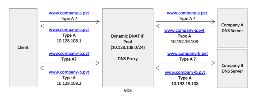
You can also configure network obfuscation to handle a situation in which a client has duplicate subnet addresses. This may occur when a client uses overlapping IP subnets, such as when it connects to one VPN from its own organization and another from the company for which they are consulting. In this scenario, you create a unique binding for an FQDN between the dynamic destination IP address and the DNS server's actual IP address.
The following figure shows an example of how to manage duplicate subnet addresses. Here, a client connects to two different organizations, Company A and Company B, using two private networks for two different organizations. When the client sends a DNS type A request for www.company-a.pvt, the VOS device forwards the request to a DNS server and receives the IPv4 address in response, here, 10.192.19.108. The client also sends a DNS type A request for www.company-b.pvt. The VOS device forwards this request to a DNS server, and also receives the IPv4 address 10.192.19.108 in response. The VOS device cannot send to the client the same IP address for both DNS requests. To resolve the issue, the VOS device requests a dynamic destination IPv4 addresses from the CGNAT pool and sends this address in response to the client request. CGNAT records the binding of routing instances, the DNS server's original IP address, and the dynamic destination IP address.

Configure DNS Proxy Profiles
- In Director view:
- Select the Configuration tab in the top menu bar.
- Select Devices > Devices in the left menu bar.
- Select an organization in the left menu bar.
- Select a Controller in the main pane. The view changes to Appliance view.
- Select the Configuration tab in the top menu bar.
- Select Networking > DNS > Proxy Profiles in the left menu bar.

- Click the
 Add icon. In the Add Proxy Profiles popup window, enter information for the following fields.

Field
Description
Name (Required)
Enter a name for the DNS profile.
Description Enter a text description for the DNS profile. Mode Select the mode to use to check the availability of the server:
- Failover
- Round-Robin
Default: Failover
- In the Resolver table, click the
 Add icon to add DNS resolvers, which resolve the domain names received in DNS requests. In the Add Resolver popup window, enter information for the following fields.

Field
Description
Name (Required)
Enter a name for the resolver profile.
Site Name Click and select an SD-WAN site to which to send traffic for DNS resolution. Configuring a site name is commonly used to optimize direct internet access (DIA) and direct cloud access (DCA). For more information, see Configure DNS Proxy with SD-WAN Traffic Steering for DIA.
Network Click and select which local WAN or LAN networks to use to proxy a DNS request.
Mode Select the mode to use to check the availability of the DNS server:
- Failover
- Round-robin
Default: Failover
SNAT Pool Select an SNAT pool to associate with the DNS profile. The address in this pool can be used to create a new proxy session. Click + SNAT Pool to add an SNAT pool. For more information, see Configure SNAT Pools.
DHCP Server Monitor (Group of Fields) (For Releases 22.1.3 and later.) Click to configure a server monitor for the server provided by DHCP. When a WAN on which DHCP is configured uses DNS servers from a service provider to resolve IP addresses, the VOS device uses the DHCP server monitor to detect that the DNS servers assigned by the service provider are incorrect or unreachable.
- Domain Name (Required)
Enter the domain name for the DNS server. - Next Hop
Enter the name of the next-hop SD-WAN site.
- Network (Required)
Enter the network used to derive the source interface.
- Interval
Click and enter the interval between monitor packets, in seconds. - Threshold
Enter the maximum number of monitor packet retransmissions before the node is declared as down.
Servers (Group of Fields) - Name (Required)
Enter a name for the DNS server. - Address
Enter the IP address of the DNS server. The address can be an IPv4 or an IPv6 address.
- Port
Enter the port number to use to connect to the DNS server.
- Monitor Object
Select a monitor object to evaluate the state of the IP addresses configured in the resolver. This evaluation is done when checking the availability of the DNS server using the method configured in the Mode field. After the evaluation, the traffic is sent accordingly.
If you do not click this field, all the IP addresses configured in the resolver appear active regardless of their actual status. Click
 Add New in the drop-down list to configure a new monitor. See Configure IP SLA Monitor Objects for more information.
 -
Click OK.
Configure DNS Policies
To direct incoming DNS requests to other DNS servers, you create a redirection rule in a DNS policy, and you then associate a DNS proxy profile with the rule.
To configure a DNS policy:
- In Director view:
- Select the Configuration tab in the top menu bar
- Select Devices > Devices in the left menu bar.
- Select an organization in the left menu bar.
- Select a Controller in the main pane. The view changes to Appliance view.
- Select the Configuration tab in the top menu bar.
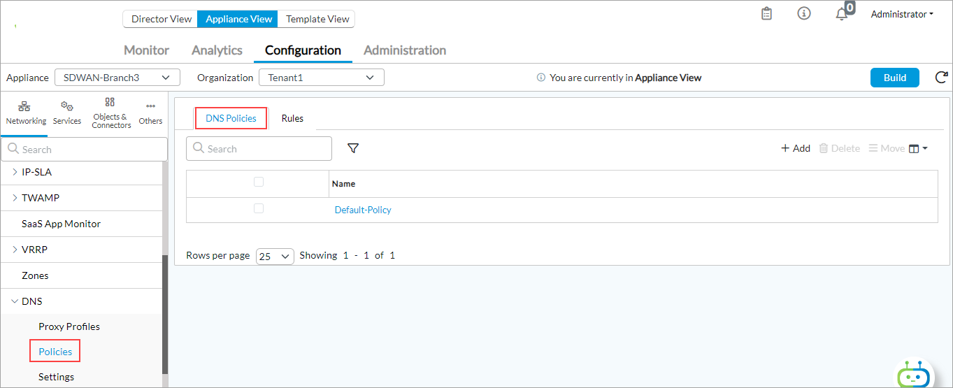
- Select Networking > DNS > Policies in the left menu bar.

- Select the DNS Policies tab in the horizontal menu bar.
- Click the
 Add icon. In the Add DNS Policy popup window, enter information for the following fields.

Field Description Name (Required) Enter a name for the DNS policy. Description Enter a text description for the DNS policy. Tags Enter a keyword or phrase that you can use to filter the rule name. Tags are useful when you have many DNS policies and want to view those that are tagged with a particular keyword. - Click OK.
Configure DNS Redirection Rules
DNS redirection rules are similar to access policy rules. Each rule has a match and action. The match can be 5-tuples, zones, region, and DNS header fields. If you create multiple DNS direction rules, the rules in a policy are evaluated in order, starting with the first one, and evaluation stops when a rule matches.
To configure a DNS redirection rule:
- If you are continuing from the previous section, skip to Step 4. Otherwise, in Director view:
- Select the Configuration tab in the top menu bar
- Select Devices > Devices in the submenu bar.
- Select an organization in the left menu bar.
- Select a Controller in the main pane. The view changes to Appliance view.
- Select the Configuration tab in the top menu bar.
- Select Networking > DNS > Policies in the left menu bar.

- Select the Rules tab in the horizontal menu.
- Click the
 Add icon. The Add Redirection Rules popup window displays.
 - Select the General tab and enter information for the following fields.

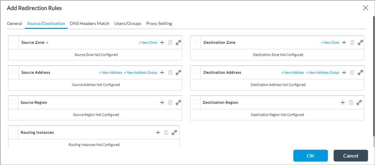
Field Description Name (Required) Enter a name for the redirection rule. Description Enter a text description for the redirection rule. - Select the Source/Destination tab to define matching criteria for incoming packets. Enter information for the following fields.

Field
Description
Source Zone (Required)
Select a zone from which the traffic originates. Click + New Zone to add a zone. For more information, see Configure Zones and Zone Protection Profiles.
Source Address
Select an address from where the traffic originates. Click + New Address to add an address. Click + New Address Group to add an address group.
Source Region (For Releases 22.1.2 and later.) Click the  Add icon, and then select a source region.
 Routing Instances (For Releases 22.1.2 and later.) Click the  Add icon to add a routing instance for the server profile.
Destination Zone
Select a zone to which the traffic is directed. Click + New Zone to add a zone.
Destination Address
Select an address to which the traffic is directed. Click + New Address to add an address. Click + New Address Group to add an address group.
Destination Region (For Releases 22.1.2 and later.) Click the  Add icon, and then select a destination region.
 -
Select the DNS Headers Match tab to define matching criteria for incoming packets. Enter information for the following fields.

Field
Description
Opcode
Select the DNS header operation code:
- IQuery
- Notify
- Query
- Status
- Update
Query (Group of Fields)
- Type
Select the type of query to associate with the rule. These are the DNS header match options corresponded the selected operation code. - Domain Name
Enter the domain name. - Negate
Click to block traffic to the domain.  Add icon
Click the  Add icon to add the query.
Advance Settings
Click to specify the number of additional records and number of questions.
In the left field, select one of the following operators: >, <,==, !=.
In the right field, enter the number.
-
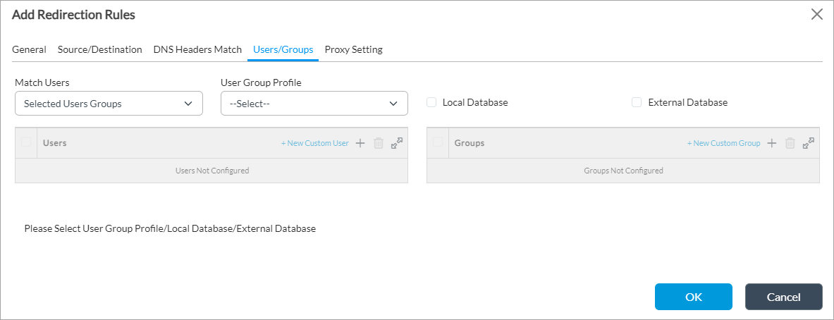
Select the Users/Groups tab to define matching criteria for incoming packets. Enter information for the following fields.

Field
Description
Match Users
Select the users to match:
-
Any
-
Known
-
Selected user groups
-
Unknown
User Group Profile When you match using a selected user group, select a user group profile to access the network in the security policy. For more information, see Configure User and Group Policy.
Local Database Click to store user and user group authentication information on the local server. External Database Click to store the user and user group authentication information on an external server. Users (For Releases 22.1.2 and later.) If you match selected users, click the  Add icon and select a user. Select + New Custom User to add a user.
Groups (For Releases 22.1.2 and later.) If you match selected users, click the  Add icon and select a user group. Select + New Custom Group to add a user group.
 -
-
Select the Proxy Setting tab to define the proxy settings for the rule. Enter information for the following fields.

Field
Description
Actions (Group of Fields) Configure the action to take when a rule matches. - Proxy Setting
Click to use proxy settings. - Server Setting
Click to use server settings. - None
Click to take no action. Proxy Setting (Group of Fields) When you select the Proxy Setting action, configure the proxy settings. - Proxy Profile
Select the name of the DNS proxy profile. Select + Proxy Profile to add a user.
- Number of Domains To Cache
Enter the number of DNS domains to cache. The DNS server uses information in its cache to respond to DNS queries.
Range: 0 through 65535
When a DNS domain entry in the DNS domain name cache times out depends on the TTL value in the DNS response, as defined in the DNS protocol. In the following example, the Answer Section for record A 216.58.194.164 has a TTL value of 47 seconds, so the DNS proxy caches the domain name for 47 seconds:
versa@versa-vm:~/$ dig www.google.com

; <<>> DiG 9.9.5-3ubuntu0.5-Ubuntu <<>> www.google.com
;; global options: +cmd
;; Got answer:
;; ->>HEADER<<- opcode: QUERY, status: NOERROR, id: 37649
;; flags: qr rd ra; QUERY: 1, ANSWER: 1, AUTHORITY: 0, ADDITIONAL: 1

;; OPT PSEUDOSECTION:
; EDNS: version: 0, flags:; udp: 4096
;; QUESTION SECTION:
;www.google.com. IN A

;; ANSWER SECTION:
www.google.com. 47 IN A 216.58.194.164

;; Query time: 252 msec
;; SERVER: 10.48.0.99#53(10.48.0.99)
;; WHEN: Tue Sep 15 22:41:22 IST 2020
;; MSG SIZE  rcvd: 59
- DNS64 Prefix
Enter the DNS extensions for network address translation from IPv6 clients to IPv4 servers. For more information, see Configure CGNAT. - Override Question
Enter the domain name to have DNS proxy override the domain name in the question section with the configured domain name before it sends the query to the server. When DNS forwards the response to the client, it restores the original domain name. - Only IPv4 WAN Available
(For Releases 22.1 and later.) Click when the WAN uses only IPv4. - Apply Policy-Based Forwarding
Click to look up SD-WAN policy rules to determine the path on which to send the DNS query.
- Network Obfuscation
(For Releases 22.1.3 and later.) Click to enable network obfuscation. - Unique IP per Client
(For Releases 22.1.3 and later.) Click to create a per-source IP address (per client) and a unique binding for the FQDN between a dynamic destination IP address and the actual server IP address. - Dynamic Destination IP Pool
(For Releases 22.1.3 and later.) Enter the name of a dynamic destination IP address pool to use for network obfuscation. For more information, see Configure CGNAT. - Cache TTL Upper Limit
(For Releases 22.1.3 and later.) Enter the upper limit of the time to live for the network obfuscation cache, in seconds. Server Setting (Group of Fields) When you select the Server Setting action, configure the server settings. - Address
For type A/AAAA DNS queries only, enter the static IPv4 or IPv6 address to send in the response to a DNS query.
- Monitor Object
(For Releases 21.2.1 and later.) Select the IP SLA monitor object to use. The DNS proxy responds to DNS query with IPv4 or IPv6 addresses whose monitor status is up. Click the
 Add icon to add the server.
Logging Setting (Group of Fields) Configure log settings. - LEF Profile
Select a LEF profile. Either select a LEF profile in this field, or else click the Default Profile box. Click + LEF Profile to add a new LEF profile. For more information, see Configure Log Export Functionality.
- Default Profile
Click to use the default LEF profile. -
Click OK.
Monitor a DNS Proxy
To check the status of a DNS proxy, issue the following command:
admin@VOS-cli> show orgs org-services t1 dns-proxy profile-monitor proxy-profile

PROFILE   RESOLVER  SERVER
NAME      NAME      NAME    STATUS
------------------------------------
internal  r1        s1      UP
external  r1        s1      UP
versa     r1        s1      UP
Note that a VOS device intercepts only those DNS requests that you have explicitly configured in a DNS policy.
For each intercepted DNS request, the VOS device creates a new session in the session table. For each DNS request that is proxied, the VOS device creates two sessions. The original session is shown as terminated on the VOS device and the destination interface is shown as “unknown”. The proxied session is shown as originating from an “unknown” interface and being destined to the interface defined in the DNS proxy profile configuration.
Supported Software Information
Releases 20.2 and later support all content described in this article, except:
- Release 21.2.1 adds support for the Monitor Object field in the Add Redirection Rules > Proxy Setting tab.
- Release 22.1 adds the Only IPv4 WAN Available field for configuring DNS redirection rules.
- Release 22.1.3 adds configuration of network obfuscation and DHCP server monitors.
Additional Information
Configure CGNAT
Configure DNS Filtering
Configure DNS Proxy with SD-WAN Traffic Steering for DIA
Configure DNS Servers
Configure Log Export Functionality
Configure SD-WAN Traffic Steering
Configure SNAT Pools
Configure User and Group Policy
Configure Zones and Zone Protection Profiles
