Configure Zones and Zone Protection Profiles
![]() For supported software information, click here.
For supported software information, click here.
For network interfaces that have identical security requirements, you group them into a single entity called a security zone, or simply, a zone. You can then associate a security policy to the zone to apply the same protections to all interfaces in the zone. For example, you might want to create zones to group interfaces that connect to WiFi hotspots or interfaces that connect to a logical group of network access points for end users that are all on the same floor in a building.
You can configure up to 1024 zones per tenant.
Associating policies with zones reduces the number of policies that you need to configure and maintain, and the policies can remain unchanged when the interfaces in a zone change.
To apply a basic level of security to network traffic as it enters a zone, you can define a zone protection profile. In this profile you define criteria to match malicious or unintended traffic, to prevent that traffic from entering the network, as illustrated in the figure below. The zone protection profile can detect and prevent the following types of traffic from entering the networks in the zone:
- Traffic floods of various protocols, such as TCP, UDP, and ICMP
- Port scans, host sweeps, and other types of reconnaissance traffic
- Malicious or spoofed packets
You can associate one zone protection profile with a zone.
You can use zone protection profiles to create trusted and untrusted zones, as illustrated in the following figure. Here, you place a zone protection profile between the untrusted zone and the trusted zone to prevent undesired types of traffic from entering the trusted zone. To filter traffic entering the trusted zone, you can also apply a firewall filter in which the source zone is the untrusted zone and the destination zone is the trusted zone.

Next-generation firewall (NGFW) rules determine inter-zone and intra-zone traffic:
- Inter-zone traffic—When you enable NGFW and do not configure NGFW rules, by default, inter-zone traffic is blocked. The implicit deny rule automatically blocks traffic.
- Intra-zone traffic (traffic to and from the same zone)—When you enable NGFW and do not configure NGFW rules, by default, intra-zone traffic is allowed. The implicit deny rule does not block this traffic. To block intra-zone traffic, configure a rule that matches the target zone for both source and destination zones, and then set the rule action as Deny. For more information, see Configure NGFW.
Configure Zones
To group together multiple interfaces that share the same security requirements, you configure a zone that contains all the interfaces. You can configure a zone on a per-tenant basis. For a given tenant, each zone must have a unique name. However, when a VOS device hosts different tenants, the tenants are isolated from each other, so the zones for two different tenants can have the same name.
To configure a zone:
- In Director view:
- Select the Configuration tab in the top menu bar.
- Select Devices > Devices in the horizontal menu bar.
- Select an organization in the left menu bar.
- Select a Controller in the main pane. The view changes to Appliance view.
- Select the Configuration tab in the top menu bar.
- Select Networking > Zones in the left menu bar. The table in the main pane displays the configured zones.
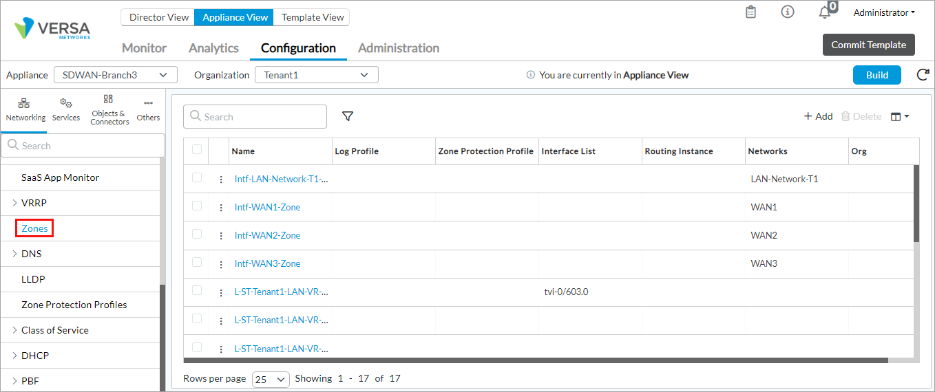
- To add a new zone, click the
 Add icon. To edit an existing zone, click the zone name.
Note: Do not select a system-generated zone to edit. This includes the following zones: host, ptvi, remote-client, versa-fileexport, and versa-speedtest.
- In the Add/Edit Zone window, enter information for the following fields.

Field Description Name (Required) Enter a name for the zone. Description Enter a text description for the zone. Tags Enter a keyword or phrase that allows you to filter the zone name. Zone Protection Profile Select a zone protection profile. This profile defines flood protection, scan protection, and traffic anomaly protection information, and it is applied to all traffic flows that enter the zone through the interfaces associated with the zone. For more information, see the Configure a Zone Protection Profile section, below. + Create Zone Protection Profile Click to create a zone protection profile. For more information, see the Configure a Zone Protection Profile section, below. Log Profile Select a log profile to use to log alarms to an external device. By default, alarms are logged in syslog. Users see all alarms on their devices. + Create Logging Profile Click to create a log profile. For more information, see Configure Log Export Functionality. Interface and Networks Click to add an interface or a network to the security zone.
- In the Interface pane, click the Add icon and select an interface from the list.
- In the Networks pane, click the Add icon and select a network from the list.
Routing Instance Click to add a routing instance to the security zone.
- In the Routing Instances pane, click the Add icon and select a routing interface from the list.
Organization Click to add an organization to the zone.
- In the Organizations pane, click the Add icon and select an organization from the list.
- In the Interface pane, click the
- Click OK.
- If you have previously associated interfaces with network objects, such as Layer 7 objects, add the network objects to the zone. When you do this, all the interfaces that belong to the network object are added to the zone.
Configure Zone Protection Profiles
You can create a zone protection profile to configure basic traffic profiling and reconnaissance detection. In the profile, you define flood protection, scan protection, and traffic anomaly protection information. A zone protection profile is applied only to the first packet of a new flow entering a zone. If a flow is idle for a while and then new packets in the flow enter the zone, the zone protection profile is not applied to the new packets because they are part of an existing flow.
You can configure multiple profiles for a tenant.
To configure a zone protection profile:
- In Director view:
- Select the Configuration tab in the top menu bar.
- Select Devices > Devices in the horizontal menu bar.
- Select an organization in the left menu bar.
- Select a Controller in the main pane. The view changes to Appliance view.
- Select the Configuration tab in the top menu bar.
- Select Networking > Zones Protection Profiles from the left panel.
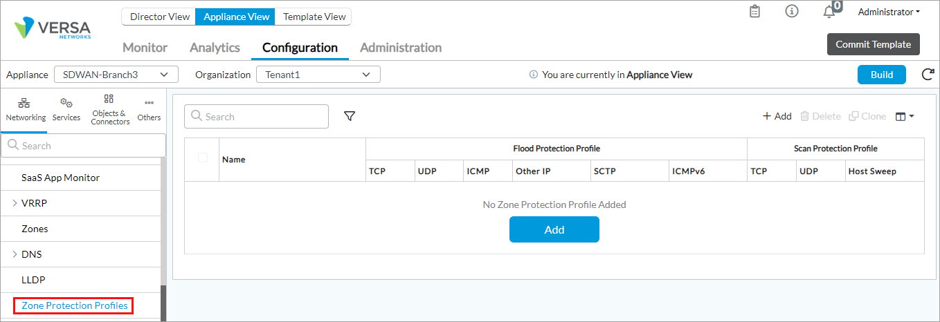
- Click the Add icon. The Add Zone Protection Profile popup window displays.
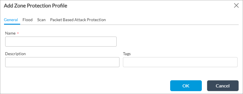
- Select the General tab and enter information for the following fields.
Field Description Name Enter a name for the zone protection profile. Description Enter a text description for the zone protection profile. Tag Enter a keyword or phrase that allows you to filter the profile name. - Select the Flood tab to configure protocol flood thresholds. Enter information for the following fields.
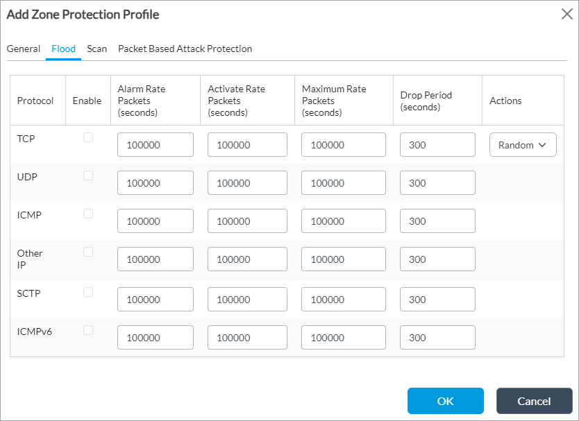
Field Description Protocol Displays the protocols for which you can configure flood thresholds:
- ICMP
- ICMPv6
- Other IP
- SCTP
- TCP
- UDP
Enable Click to select the protocol for which to enable flood protection. Alarm Rate Enter the threshold value, in packets per second (pps), at which to generate an alarm. When the number of packets received matches or exceeds this value, an alarm is generated.
Range: 1 through 20000000 pps
Default: 100000 pps
Active Rate Enter the threshold value, in pps, at which to activate the random early detection (RED) action. When the number of packets received matches or exceeds this value, packets are randomly dropped.
Range: 1 through 20000000 pps
Default: 100000 pps
Maximum Rate Enter the threshold value, in pps, at which to drop all packets. When the number of packets received matches or exceeds this value, all packets are dropped.
Range: 1 through 20000000 pps
Default: 100000 pps
Drop Period Enter a value for how long to drop packets.
Range: 1 through 18000 seconds
Default: 300 seconds
Actions For TCP, select the action to take when the active rate threshold is exceeded:
- Random Early Drops—Randomly drop packets.
- SYN Cookies—Generate an acknowledgment, and ensure that the connection is not dropped during a SYN flood attack. This is the default.
Default: SYN Cookies
- Select the Scan tab to configure the scan intervals and thresholds. Enter information for the following fields.

Field Description Scan Displays the protocols and other objects for which you can configure scanning intervals and thresholds:
- Host sweep
- TCP
- UDP
Enable Click to select the protocol or object for which to enable scan protection.
Actions Select the action to perform when an abnormal network scan is detected:
- Allow—Run the scan
- Alert—Generate an alert
Interval (Sec) Enter a value for how often to scan traffic.
Range: 1 through 65535 seconds
Default: 30 seconds
Recommended Value: 30 seconds or less. Configuring a higher value can increase memory utilization on the VOS device.Threshold (Events) Enter a threshold value for events. When the number of events received matches or exceeds this value, an alarm is generated.
Range: 1 through 65535
Default: 300
- Select the Packet-Based Attack Protection tab to protect the network from invalid data packets and other anomalous traffic.
- Select the UDP/TCP/IP Discard tab and enter information for the following fields.

Field Description IP Frag Click to drop fragmented packets. IP Spoof Click to drop spoofed packets, which are packets that are received on one interface but that have a different outgoing interface. Reject Non-SYN TCP Click to drop packets in a session if the first packet has a non-SYN flag. UDP Malformed Click to drop packets in te case of a checksum error. IP Options Select one or more IP options. The IP options are defined RFC 791 and RFC 1108. - Security—Allows hosts to send security and other parameters (IP option 130; RFCs 791 and 1108).
- Stream—Stream identifier (IP option 136; RFCs 791 and 1108).
- Unknown—IP options field is unknown.
- Malformed—IP options field is formatted incorrectly.
- Loose-source routing—Routes IP packets based on information provided by the source (IP option 3; RFC 791).
- Strict-source routing—Routes IP packets based on information provided by the source (IP option 137; RFC 791).
- Timestamp—Timestamp information (IP option 4; RFC 791).
- Record route—Routes IP packets based on information provided by the source (IP option 7; RFC 791).
IPv6 Options (For Releases 23.1.1 and later.) Select one or more IPv6 options:
- Hop by Hop Extension Header—Discard packets with hop-by-hop extension header.
- Routing Extension Header—Discard packets with routing extension header.
- Destination Extension Header—Discard packets with destination extension header.
- Invalid Hop by Hop Extension Header—Discard packets with invalid hop-by-hop header type.
- Invalid Routing Header Type—Discard packets with invalid routing header type.
- Invalid Destination Header Type—Discard packets with invalid destination header type.
- Undefined Destination or Hop by Hop Header Type—Discard packets with undefined destination or hop-by-hop header type.
- Undetermined Transport Layer—Discard packets with undetermined transport layer.
- Logging—Enable or disable LEF logging for discarded IPv6 packets.
- Select the ICMP tab, and then enter information for the following fields.

Field Description Ping Zero ID Click to drop ICMP ping packets whose identifier value is 0.
Fragment Click to drop packets that contain ICMP fragments. Large Packet Click to drop ICMP packets larger than 1024 bytes. Error Message Click to drop packets if the ping request generated error messages. Malformed Packet Click to drop malformed ICMP packets. - Click OK.
View Zone Protection Logs
To view the zone protection logs on Versa Analytics:
- In Director view, select the Analytics tab.
- Select Logs > Threat Detection > DoS Threat Logs in the left menu bar. The zone protection logs display. For example:


Note that for zone protection profiles, the Attacker and Victim columns are not populated, because the purpose of the profile is to limit the rate at which sessions are created. The Attacker and Victim columns are populated only when you configure a classified DoS profile in which you configure the Classification Key field to be either both Destination IP Only and Source IP Only, or Source and Destination IP. For more information, see Configure DoS Protection.
Supported Software Information
Releases 20.2 and later support all content described in this article, except:
- Release 23.1.1 adds support for IPv6 options when configuring a zone protection profile.
Additional Information
Configure Basic Features
Configure DoS Protection
Configure Layer 7 Objects