Configure Profiles
![]() For supported software information, click here.
For supported software information, click here.
You use the Configure lifecycle to create all configuration objects for Secure SD-WAN deployments. The Concerto configuration objects are hierarchical and consist of master profiles, subprofiles, policies, and rules. A master profile contains one or more subprofiles, a subprofile contains one or more policies, and a policy contains one or more rules. For more information, see Configuration Hierarchies.
To access the Configure lifecycle screen, select Configure in the left menu bar on the Concerto tenant's home screen. Then select Secure SD-WAN > Profiles.

The following figure shows a Configure lifecycle screen that displays the basic master profile (Default-Basic-MP), the default active-active HA profile (Default-Active-Active), and the basic subtenant master profile (Default-Basic-MP-Sub-Tenant, for Releases 11.2.1 and later).

Profile Types
The Concerto orchestrator has two types of profiles: master profiles and subprofiles.
Master profiles are configuration templates that you can apply to one or more appliances. Each master profile consists of subprofiles. There are two types of master profiles:
- Basic—Includes a subset of the available configuration objects. You can build most configuration objects in the basic master profile in the same way that you build them in standard master profiles. For Releases 11.2.1 and later, the subtenant basic master profile allows you to configure security and application services. The basic master profile provides a simple user experience and eliminates the subprofiles hierarchy. Instead of creating subprofiles, you create policies and rules and then attach them directly to the basic master profile. For Releases 11.2.1 and later, a master profile can be for a single tenant or for multiple tenants.
- Standard—Includes all available configuration objects and provides more configuration options.
The following types of subprofiles are available:
- Application—Use to create QoS and traffic-steering policies.
- Device—Use to create BGP peer, interface, and radio policies.
- Network Services—Use to create CGNAT, DHCP, and WLAN policies.
- Security—Use to create access control, antivirus, IP-filtering, IPS, and URL-filtering policies
- Topology—Use to create VPN policies, including branch and hub policies.
- System—Use to create policies for management servers, user management, ALG configurations, settings for time zone, user and device authentication profiles, and user and device authentication policies.
Default Master Profiles
When you install the Concerto software or create a new tenant, Concerto automatically builds three default basic master profiles for the tenant:
- Default-Basic-MP-Sub-Tenant (Sub Tenant)
- Default-Active-Active
- Default-Basic-MP-Sub-Tenant (for Releases 11.2.1 and later)
The default master profiles consist of preconfigured network, security, and application objects, as shown below. The default basic subtenent master profile consists of only application and security objects. Concerto creates these basic master profiles automatically for each tenant on Concerto. You can customize the Default-Basic-MP master profile and use it for single-appliance or multitenant site deployments. You can customize the Default-Active-Active master profile and use it for active–active appliance HA site and multitenant deployments. The following screen shows the default master profiles in List view.

For each master profile, you can perform the following actions:
- Edit (
 )— Click to a basic master profile. Editing a master profile creates a new version, which is assigned a new version number, and the original default master profile remains.
 - Delete (
 )—Click to delete the master profile.
 - References (
 )—Click to view all the appliances using this master profile.
 - Ellipses (
 )—Click to display the following options:

- Clone—Click to create a new master profile based on the basic master profile. After you make changes to the configuration objects, save it with a unique name.
- Disable Auto Delete—Click to disable auto delete.
The following screen shows the default master profiles in Tile view.

Click the ![]() Ellipses icon to display a pop-up window with the same options that were shown in the List view above.
Ellipses icon to display a pop-up window with the same options that were shown in the List view above.

For HA deployments, a default active–active HA basic master profile is provided. You can build active-active HA profiles directly in the default active–active HA basic master profile. The following figure below shows the network diagram for the default active–active HA master profile.
Note: Before using the built-in default basic master profiles, do the following:
- Set the connection names on each WAN interface under the Connection tab
- Set the Direct Internet Access connection names under VPN Instances under the Others tab.
If you do not set the connection names used on the appliances in the master profile, when you try to publish the master profile to an appliance, the publish process fails. For more information, see Make Mandatory Updates to the Default Basic Master Profile.
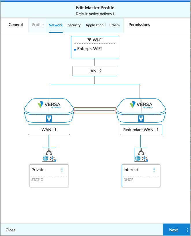
To create an active–active HA deployment, you create a single profile and use it on both the primary and secondary HA appliances. All configuration changes and bind-variable values assignments are made on the primary appliance, even if they are meant for the secondary appliance. After you create the configuration for the primary appliance, Concerto uses that configuration to build the configuration for the secondary appliance in the HA pair. After you configure both HA appliances, you publish each of the appliances separately to create the HA deployment.
The cross-connect interface shown in the figure above is optional. If the WAN interfaces on both the primary and secondary appliances are the same, that is, if the circuits are the same in each WAN interface, you do not need to add the cross-connect interface. If you do need the cross-connect, you configure it in the same way as any other interface type.
You can also convert any non-HA master profile to active–active mode by simply adding a redundant WAN interface to it. Redundant WAN interfaces are attached to the secondary appliance.
For Releases 11.2.1 and later, Concerto provides a default subtenant basic master profile at the subtenant level. You use a subtenant standard master profile to configure security and application services for a subtenant. The subtenant basic master profile does not support other services.

Make Mandatory Updates to the Default Basic Master Profile
When you create a new tenant in the Concerto orchestrator, several built-in configuration objects are created, and they are packaged with the Concerto software. One of the built-in objects is the default basic master profile, which is named Default-Basic-MP.v1. You must update this profile before using it on an appliance. You can also clone this basic master profile and modify it before applying it to an appliance.
In the Default-Basic-MP.v1 object, the following interfaces are preconfigured:
- Three WAN interfaces
- Two wired interfaces, named Private and Internet
- One LTE interface
- Two LAN interfaces
- One wired LAN interface
- One enterprise WiFi interface
The following figure shows the default WAN and LAN interfaces in the default basic master profile. The Type field shows that the master profile is a basic master profile.

Before you use the default basic master profile on an appliance, you must disable the interfaces that are not required and then associate them with one of the WAN connections (the WAN networks defined on the Director node). You must also set the direct internet access connection names under VPN Instances.
To make the mandatory updates to the default basic master profile:
- In Tenant view, select the Configure lifecycle in the left menu bar.
- Select Profiles > Master Profiles.
- Select the Default-Basic-MP profile in the main pane. The Edit Master Profile screen displays.
- Select the Profile tab. The Network subtab displays, showing a diagram of the network.

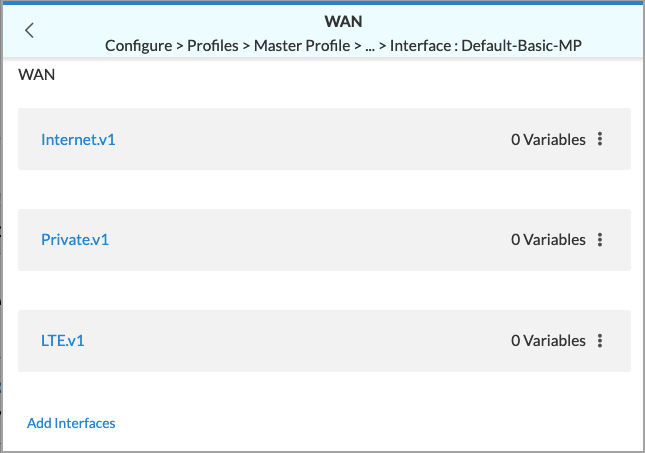
- Click the WAN box in the network diagram. The WAN screen displays the three WAN interfaces. Because these interfaces are specific to each deployment, the default basic master profile is not preconfigured with connection names for the WAN interfaces.
- Click an interface name. The Edit Interface screen displays.
- Click the Connection tab, and then select a connection in the Connection Name field. The following screenshot shows that the Internet-1 connection is selected.

- Repeat Step 7 for the other two WAN interfaces.
- To set the direct internet access connection names, click the Others tab in the Edit Master Profile screen.

- Click the VPN instances box. The VPN Instances screen displays.

- Click a VPN instance. The Edit VPN Instance screen displays.

- Under Split Tunnels, click the slider bar to enable Direct Internet Access (DIA).
- Under Connection Name, select a connection, and then under Priority, select a priority for the direct internet access (DIA) connection.
- Click the Permissions tab, and then click Save. A message displays at the top of the Configuration screen confirming that the basic master profile has been updated successfully.
Make Optional Updates to the Default Basic Master Profile
Based on your site configuration requirements, you may need to create a new basic master profile. To do this, you clone the Default-Basic-MP.v1 master profile and then update it as needed. The following are some of the common changes you can make to the master profile:
- Configure a multitenant master profile.
- Disable the LTE interface.
- Enable or disable DIA.
- Update the authentication protocol for the WiFi interface.
- Add traffic steering, QoS, and security rules.
- Update or add services.
Configure a Multitenant Basic Master Profile
For Releases 11.2.1 and later.
You can edit a default active–active master profile or default basic master profile to allow multitenancy. With a multitenant basic master profile, you can create multitenant appliances for a provider organization. You can create new subtenants, and you can attach existing subtenants while publishing the provider organization appliance that uses the multitenant master profile. Appliances are automatically created in the subtenants associated with a provider appliance that uses a multitenant master profile.
In a multitenant basic master profile, you create interfaces for subtenants in the provider tenant profile. Because interfaces, networks, and routing instances are common appliance resources, configuring them at the provider tenant level avoids overlapping of the configuration among tenants. For example, multiple tenants can use vni-0/0.1 independently on the same appliance. Having shared resources such as interfaces helps to avoid such misconfiguration and simplify the implementation. You configure interfaces and routing on a multitenant appliance at the provider tenant level. The provider user can mark each interface for the subtenant to which it belongs. The remainder of the service configuration, such as security, traffic steering, and application QoS, can be performed at the subtenant level by subtenant or provider tenant users.
To configure a multitenant basic master profile:
- Configure the scope of the default active–active (Default-Active-Active) or default basic master profile (Default-Basic-MP) to multitenant.
- Click the basic master profile.
- In Edit Master Profile > General, select Multitenant in the Scope field.

- Configure subtenant LAN interfaces for subtenants that are associated with the provider organization. By default, the master profile contains a LAN interface. Note that you can create subtenant LAN interfaces only for basic master profiles of type Multitenant.
- Select Edit Master Profile > Profile. The Network subtab displays, showing a diagram of the network.

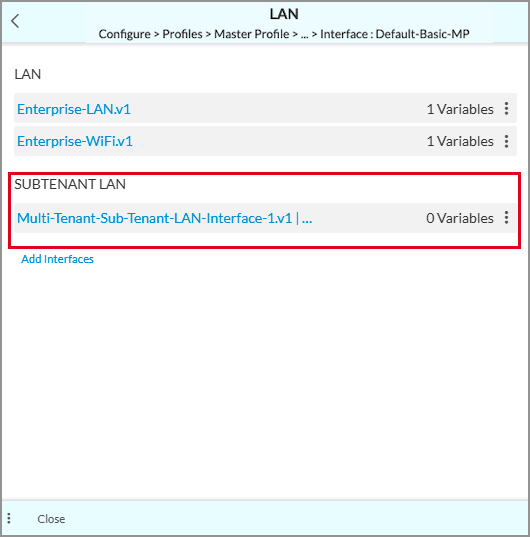
- Click the LAN box. The LAN screen displays any existing LANs.

- Click Add Interfaces, then click Create New. In the Create Interface screen, enter information for the following fields.

Field Description Name Enter a name for the subtenant LAN interface. Category Select Subtenant LAN. Location Select a location SubTenant Select the subtenant for which you are creating the subtenant LAN interface - Click Next. The Address and Routing tab displays.
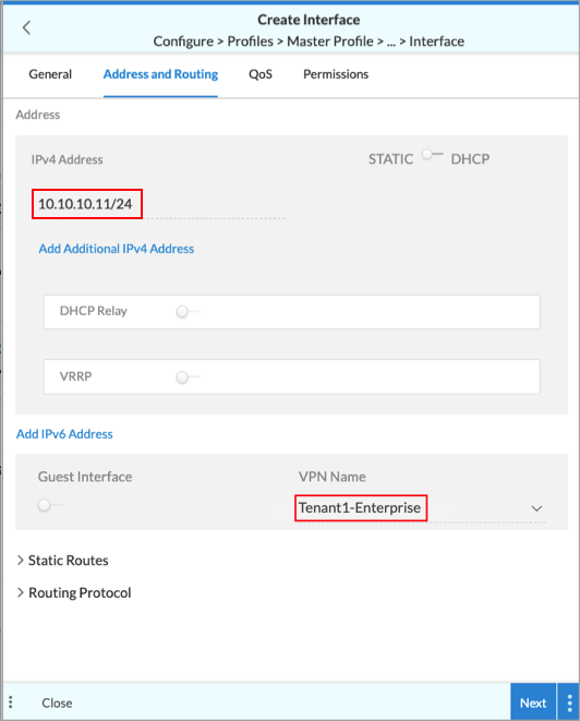
- Enter the IPv4 address for the LAN interface.
- In the VPN Name field, select the tenant's VPN. By default, the VPN of the tenant you selected in the General tab is displayed.
- Enter information in the other fields, and the save the subtenant LAN interface. The interface that you add is displayed under Subtenant LAN. For example:
- Repeat this step for each subtenant.
- Select Edit Master Profile > Profile. The Network subtab displays, showing a diagram of the network.
- Create VPN instances to associate subtenant VPNs with the master profile for the provider organization.
- In Edit Master Profile > Profile, select the Others tab.

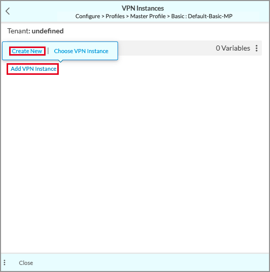
- Click the VPN Instance field. In the VPN Instances screen, click Add VPN Instance, and then click Create New.
- In the VPN Instance screen, select the Settings tab.
- Enter a name for the VPN instance for the tenant.
- Under VPN, select the tenant for which to create VPN instance.
- Under Split Tunnels, click the slider bar to enable Direct Internet Access (DIA).
- Enter information in the other fields.
- Click Next, and then save the VPN instance. The VPN instance displays in the VPN Instances screen.
- Under Connection Name, select a connection, and then under Priority, select a priority for the direct internet access (DIA) connection.
- Click the Permissions tab, and then click Save. A message displays at the top of the Configuration screen confirming that the basic master profile has been updated successfully.
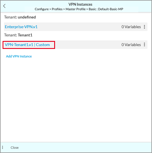
- Repeat this step for all subtenant VPNs.
- In Edit Master Profile > Profile, select the Others tab.
- After you update the master profile, deploy the appliance associated with the master profile. When you publish, Concerto creates a subtenant appliance in each of the subtenants. For more information, see Concerto Deploy Lifecycle Overview.
Edit the Subtenant Basic Master Profile
For Releases 11.2.1 and later.
You can use a subtenant standard master profile to configure security and application services for a provider organization.
To edit a subtenant basic master profile:
- Click the basic subtenant master profile, which the GUI displays as Default-Basic-MP-subtenant. You cannot edit the Type and Scope fields.

- Click Next. The Profile > Security tab displays.

- Modify the security policies, if required. (For Releases 12.1.1 and later.) To modify the security policy, on the Policies tab, click the policy name. The Add Access Control Policy window displays. For more information, see Update Security Policies and Rules, below.
- Modify the security profiles, if required. (For Releases 12.1.1 and later.) Select the Profiles tab, and then modify the security profiles. For more information, see Update Security Policies and Rules, below.

- Select the Application tab, and then modify the QoS and traffic-steering policies, if required. For more information, see Configure QoS Policies and Rules and Configure Traffic-Steering Policies and Rules, below.

- Make other changes in the Others and Permissions tabs.
- Save the subtenant basic master profile.
Disable the LTE Interface
- In Edit Master Profile > Profile > Network, click the
 Ellipses icon in the LTE box, and then select Edit. The Edit Interface screen displays.

- Click the Enabled indicator so that it is grayed out. The LTE interface is disabled.

Enable or Disable DIA on a WAN Interface
- In Edit Master Profile > Profile > Network, click the interface on which to enable or disable DIA. The Edit Interface screen displays.

- In the Connection Name field, configure a name for the interface. Configure the connection name before you change the connection type.
- In Edit Master Profile > Profile > Network, click the
 VPN Only icon for the interface you are changing.
 - To enable DIA, click the
 Internet and VPN (Split Tunnel) icon. To disable DIA, click the VPN Only icon.
 - Select the Permissions tab, and then click Save.
Enable a Speed-Test Server on a WAN Interface
To troubleshoot link speed issues, you can configure a WAN interface to be a speed-test server.
To configure a WAN interface to be a speed-test server:
- In Edit Master Profile > Profile > Network, click the interface on which to enable the speed-test server. The Edit Interface screen displays.

- Select the General tab.
- In the Speed-Test Server field, click the
 slider to enable a server.
 - Ensure that the interface category is WAN.
- Select the Permissions tab, and then click Save.
Update the WiFi Interface Authentication Protocol
- In Edit Master Profile > Profile > Network, click the WiFi box.

The WLAN screen displays.

- Click the Ellipses icon of the WLAN network that you want to update, and then click Edit. The Edit WLAN screen displays.
- Select the Advanced tab. The following screen displays.

- For Wired Equivalent Privacy (WEP)-based authentication, enter information for the following fields.
Field Description Authentication (Group of Fields) - Protocol
Select the protocol:
- WEP Auto
- WEP Open
- WEP Shared Key
- Key Length
Select the key length:
- 64 bits
- 128 bits
- Key Type
Use the
slider bar to select the key type:- ASCII
- HEX
- Key Text
For the ASCII as the key type, enter 5 characters for the key text.
For the HEX key type, enter 10 characters for the key text.
Interface Name Click in the Name field, and then select an interface name. - For WiFi Protected Access (WPA)-based authentication, enter information for the following fields.

Field Description Authentication (Group of Fields) - Protocol
Select the protocol:
- WPA
- WPA/WPA2 Auto
- WPA2
- Mode
User the
slider bar to select the mode:- Enterprise
- Personal
- Passphrase
Enter a passphrase (password), which can be from 8 to 63 characters. - Encryption
Select the encryption type:
- Auto
- CCMP
- Temporal Key Integrity Protocol (TKIP)
Interface Name Click in the Name field and select an interface name. - Click Next, or select the Permissions tab, and then Click Save.
Update Security Policies and Rules
- In the Edit Master Profile screen, select Profile > Security. The Policies tab displays the security policies, if any, that are associated with the master profile. In the example screen below, there is one policy listed, Default-AccessControl.v1.

- To update a policy, click the policy name. In this example, if you click on the Default-AccessControl.v1 policy, the Add Access Control Policy screen displays with the Review & Submit tab selected by default.

- Review the configuration and make any needed changes by clicking the
 Edit icon in each section.
 - Click Save when you have finished updating the policy.
- (For Releases 12.1.1 and later.) Select the Profiles tab to view the configured security profiles. The following screen displays.

- To update a security profile, click a profile name to display information about the profile. For example, if you select the Default-AntiVirus.v1 profile, the Add Malware Protection Profile screen displays with the Review & Submit tab selected by default.

- Review the configuration and make any needed changes by clicking the Edit icon in each section.
- Click Save when you have finished updating the profile.
- To create a new rule or choose an existing rule for a policy, select the Rules tab, see Create a New Rule, below.
Configure QoS Policies and Rules
For information about configuring QoS policies and rules, see Configure QoS Policies and Rules.
Configure Traffic-Steering Policies and Rules
For information about configuring traffic-steering policies and rules, see Configure Traffic-Steering Policies and Rules.
Update or Add Services
As of Release 12.2.2, you can update or add the following services:
- ALG Configurations (Configure Application Layer Gateway (ALG))
- BGP Peer Policy
- CGNAT
- DHCP
- Director Service Templates (Configure a Secure SD-WAN Tenant), (Configure Bind Variables on Active–Active HA Appliances)
- DNS Proxy Policy (Configure DNS Proxy for Concerto)
- DNS Proxy Profile (Configure DNS Proxy for Concerto)
- Management Servers (Configure Management Servers)
- Redistribution Policy (Configure Redistribution Policies in Concerto)
- Settings (Configure Tenant System Settings Profiles)
- User and Device Authentication Policies (Configure SD-WAN User and Device Authentication)
- User and Device Authentication Profiles (Configure SD-WAN User and Device Authentication)
- User Management (Manage VOS Users)
- VPN instances
To update or add services, go to Configure > Secure SD-WAN > Profiles > Master Profiles, then select a master profile. The following screen displays.

Configure the DHCP Service
- To add a new DHCP service or update an existing DHCP service, click the DHCP box in the Edit Master Profile > Profile > Others screen. The DHCP screen displays.
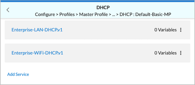
- To display or update information about the service, click an existing DHCP service, such as Enterprise-LAN-DHCP.v1 in the screenshot above. Make the changes, then click Save on the Permissions screen.
- To add a new DHCP service, click Add Service. You can create a new service or choose an existing service.
- If you select Choose Services, the following screen displays.

- Click the service to add and then click Add at the bottom of the screen.
- If you select Create New, the following screen displays. Enter information of the following fields.
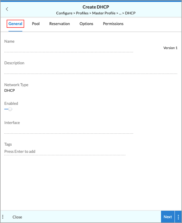
Field Description Name (Required) Enter a name for the DHCP service. Description Enter a description of the DHCP service. Enabled Click the slider bar to enable the DHCP service (default). Click Enabled again to disable the service. Interface (Required) Click in the field and select an interface to use for the DHCP service. Tags Enter one or more tags. A tag is an alphanumeric text descriptor with no spaces or special characters. You can specify multiple tags added for the same object. The tags are used for searching the objects.
- If you select Choose Services, the following screen displays.
- Click Next. In the Pool tab, enter information for the following fields.

Field Description Scope (Group of Fields) - Start Index
Enter the start index for the DHCP pool. The start index is the index of the first host address in the DHCP pool. The start index is automatically computed by the system based on the LAN interface IP address subnet. For example, for a LAN interface with the address 192.168.0.1/24 and a start index of 2, the DHCP server pool starting address would be 192.168.0.2. - Pool Size
Enter the size of the DHCP address pool. The end address of the pool is measured using the LAN interface IP subnet, start index, and pool size. For example, for an interface with the address 192.168.0.1/24, start index 2, and pool size 250, the pool range would be 192.168.0.2 through192.168.0.251. - Exclude
Enter a list of pool indexes to exclude. The list can be individual indexes or ranges, such as 67-90. The system will automatically compute the exclude addresses in the IP subnet configured on the LAN interface. Name Servers By default the name server is assigned automatically (the slider bar is set to AUTO). If you select MANUAL, enter the following information. - Primary
Enter the IP address address of the primary name server, such as 10.10.10.1. - Secondary
Enter the IP address address of the secondary name server. Domain Enter the domain name of the DHCP service, such as versa-networks.com. - Click Next. The Reservation tab displays.

- Click Add to add a DHCP reservation, then enter information for the following fields.

Field Description MAC Address Enter the MAC Address of the DHCP Client, for example 0d:56:45:52:53:41. Reserve Address Enter the number of indexes to reserve in the IP address pool for the corresponding MAC addresses. The system will automatically compute reservations based on the IP subnet configured on the LAN interface. The number entered must be greater than 0. - Click Next. The Options tab displays.

Field Description DHCP Options (Group of Fields) Click Add to add one or more DHCP options, then enter information for the following fields.

- Key
Enter a number for the DHCP options key. - Type
Select an option type. The supported options are:
- Boolean
- FQDN
- IP Address
- IPv6 Address
- String
- uint8
- uint16
- uint32
- Hex String
- Vendor ID
Enter the vendor information if vendor information is exchanged between the DHCP server and client. - Value
Enter a value for the vendor ID, then click the Check icon to add the value. The value depends on the Option type you selected, as follows.
- Boolean—Enter true or false.
- FQDN—Enter a fully qualified domain name (FQDN).
- IP Address—Enter an IPv4 address.
- IPv6 Address—Enter an IPv6 address.
- String—Enter a text string.
- uint8—Enter a number from 0 through 255.
- uint16—Enter a number from 0 through 65535.
- uint32—Enter a number from 0 through 4294967295.
- Hex String—Enter a valid hexadecimal string.
Boot Options (Group of Fields) - File Name
Enter the name of the file to use to boot the DHCP client. - Next Server
Enter a valid IP address of the next DHCP server in the boot sequence.. - Echo Client ID
Click the slider bar to enable or disable the echo client ID option. The default is Enabled. Netbios Options - Name Servers
Enter the IP address of the Windows Name Internet Server (WINS) to use for name resolution. - Type
Select the node type of name resolution:
- b—Broadcast. A b-node client sends the destination name in a broadcast message.
- h—Hybrid. An h-node client unicasts the destination name to the WINS server.
- m—Mixed. An m-node client broadcasts the destination name.
- p—Peer to peer. A p-node client sends the destination name in a unicast message to the WINS server.
- Click Next. The Permissions tab displays.

- Review and edit the permissions, if desired.
- Click Save to create the DHCP service.
Configure the CGNAT Service
- To add a new CGNAT service or update an existing CGNAT service, click the CGNAT box in the Edit Master Profile > Profile > Others screen. The CGNAT screen displays.

- To add or update an existing CGNAT service, click CGNAT. In the CGNAT screen, click Add Service to add a new service. You can create a new service or choose an existing service. If you select Create New, the Create CGNAT screen displays. Enter information for the following fields.

Field Description Name Enter a name for the CGNAT service. Enable The slider bar is in the Enabled position by default. To disable the CGNAT service, click the slider bar so that it is grayed out.

NAT Mode Select the NAT mode:
- Basic NAT. This is the default.
- Destination NAT
- Dynamic NAT
- NAPT
- Twice Basic NAT
- No Translation
Default: Basic NAT
Tenant (For Releases 11.4.1 and later.) Select a tenant. The list displays the current tenant and all child tenants. If a tenant is not selected, the system displays the name of the current tenant only, not any child tenants. - Select the Criteria tab, and then enter information for the following fields.

Field Description Type (Source) The Source type is selected by default, and you cannot change it. Select the type of source to use:
- IP Ranges—Enter an IP address range, such as 10.10.1.1-10.10.1.100, and then click the
 Check mark icon or press Enter. You can enter multiple address ranges.
 - Subnets—Enter an IP address subnet, such as 10.1.1.0/24.
- VPN Name—Select a VPN name.
- Zones—Select a zone.
Type (Destination) The Destination type is selected by default, and you cannot change it. Select the type of destination to use:
Note: The IP Ranges and Subnets options are mutually exclusive; you can select one or the other, but you cannot select both of them.
- IP Ranges—Enter an IP address range, such as 10.10.1.1- 10.10.1.100, then click the Check mark icon or press Enter. You can enter multiple address ranges.
- Port—Enter a destination port number.
Range: 1 through 65535
Default: None - Port Range—Enter a destination port range, such as 80-88.
- Subnets—Enter an IP address subnet, such as 10.1.1.0/24.
- Zones—Select a zone.
Protocols Select one or more protocols:
- AH
- ESP
- ICMP
- TCP
- UDP
- 0 through 255
- IP Ranges—Enter an IP address range, such as 10.10.1.1-10.10.1.100, and then click the
- Select the Action tab, and then enter information for the following fields.

Field Description Logging Click the slider bar to enable logging to Versa Analytics.Translated Sources Select the translated sources based on VPN names or WAN connections:
- VPN Name—Select a VPN name.
- WAN Connection—Select a WAN connection.
Select the translated sources from IP addresses, subnets, or IP address ranges:
- IP Addresses—Enter an IP address, and then click the Check mark icon or press Enter. You can enter multiple IP addresses.
- IP Ranges—Enter an IP address range, and then click the Check mark icon or press Enter. You can enter multiple IP address ranges.
- Subnets—Enter an IP subnet, and then the Check mark icon or press Enter. You can enter multiple IP subnets.
- Select the Permissions tab, and revise the permissions, if needed.
- Click Save to create the CGNAT service.
Configure VPN Instances
- To add new VPN instances or display existing VPN instances, click VPN. The VPN Instances screen displays.
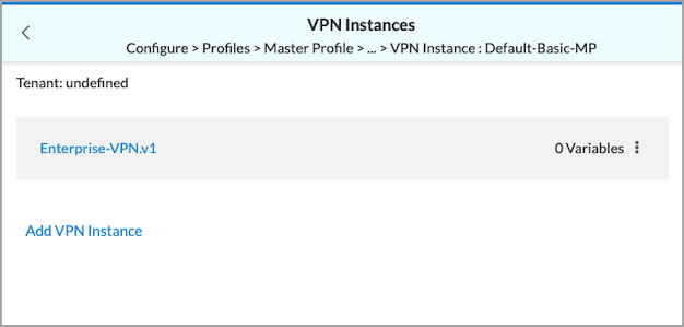
- To add a VPN instance, click Add VPN Instance > Create New.

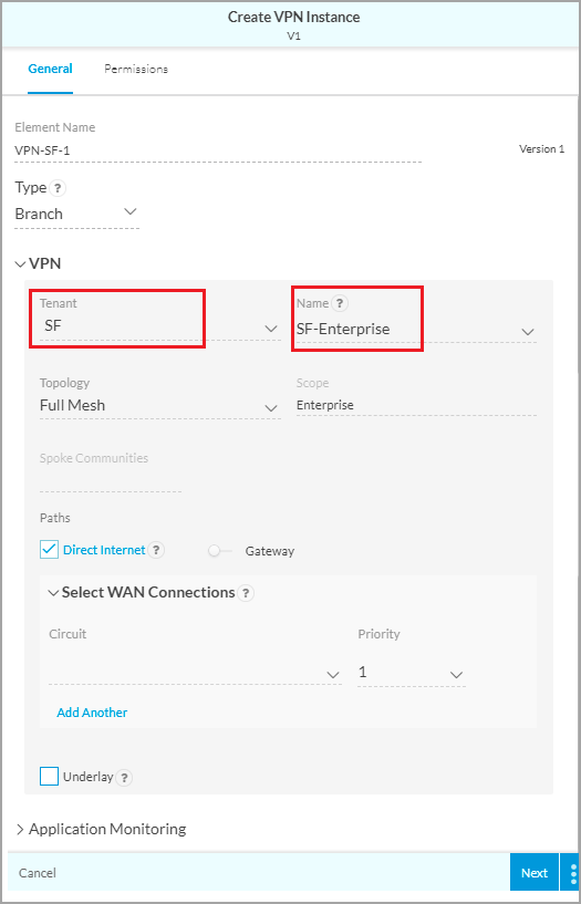
The Edit VPN Instance screen displays with the Settings tab selected by default. Enter information for the following fields.
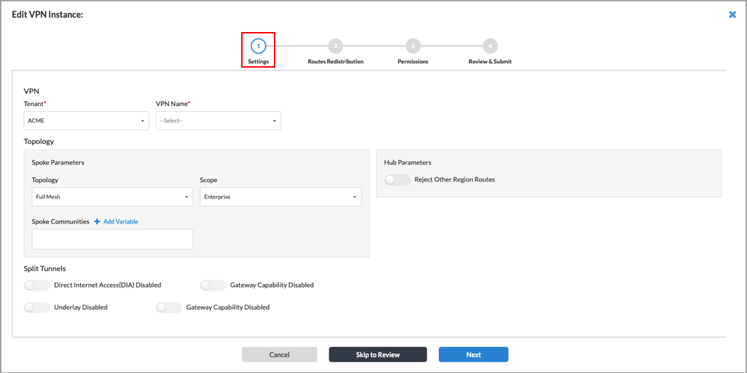
Field Description VPN (Group of Fields) - Tenant (Required)
Select a tenant from the list. - VPN Name (Required)
Select a VPN from the list. Topology (Group of Fields) - Spoke Parameters
- Topology
Select a topology. The options are:
- Full Mesh
- Spoke to Hub Only
- Spoke to Spoke via Hub
- Scope
Select Enterprise or Region from the list. If you select Region, the following field appears:
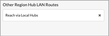
Select a hub LAN route. The options are:
- Reach Directly
- Reach via Local Hubs (default)
- Reject
- Hub Parameters
- Reject Other Region Routes
Enabled by default. To disable this option, click the slider bar so that it is grayed out.

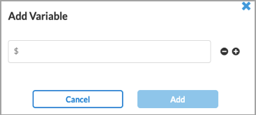
- Spoke Communities
Enter one or more spoke community numbers. - + Add Variable
Click to create a variable for a spoke community, then enter the variable name in the popup window. You can add multiple variables.
Split Tunnels (Group of Fields) - Direct Internet Access (DIA) Disabled
Click the slider bar to enable DIA (DIA is disabled by default, then enter information the following fields.

- Connection Name—Select the connection to use for DIA.
- Priority—Select a priority for the connection, then click the
 Plus icon. The priority range is 1 through 16.
You can select multiple connections.
If you enable Gateway, the appliance acts as an internet gateway for the enterprise and re-advertises default routes on the SD-WAN overlay to other appliances.
- Gateway Capability Disabled
Click the slider bar to allow the DIA connection to be a gateway. If you enable Gateway, the appliance acts as a gateway to non-SD-WAN networks and re-advertises routes from the MPLS underlay to the SD-WAN overlay. - Underlay Disabled
Click the slider to enable underlay routing to non-SD-WAN appliances over the MPLS network without performing NAT on the traffic. Underlay routing is disabled by default.

Enter information the following fields.
- Connection Name—Select the connection to use for underlay routing.
- Priority—Select a priority for the connection, then click the Plus icon. The priority range is 1 through 16.
You can select multiple connections.
- Gateway Capability Disabled
Click the slider bar to prevent the VPN from being a gateway. - Click Next. In the Routes Redistribution tab screen, enter the following information.
Note: By default, the redistribution policy configuration is automatically generated by the system based on the routing protocols enabled on the LAN interfaces and the type of the device (hub, hub-controller, spoke, full mesh). For most use cases you are not required to create redistribution policies. Use custom redistribution policies only if you need to overwrite the default configuration.

Field Description From RIB (Required) Select IPv4 unicast or IPv6 unicast. Destination Protocol (Required) Select the destination protocol. The options are:
- BGP
- OSPF
- RIP
Redistribution Policy Name (Required) Select the name of the redistribution policy. For information about creating a redistribution policy, see Configure Redistribution Policies in Concerto. - Click Next. In the Permissions tab, you can change permissions for the defined roles, if desired.

- Click Next. The Review and Submit screen displays.

- Enter a name for the VPN instance in the Name field.
- Review the configuration. To make changes, click the Edit icon, make the changes, and then return to this screen.
- Click Save to create the VPN instance.
Configure BGP Peer Policies
- To add a new BGP peer policy or update an existing policy, click + BGP Peer Policy.
Note: If you refer to a BGP peer policy in the BGP neighbor configuration on a WAN or LAN interface, you should attach the peer policy to the BGP peer policies list. For more information, see Configure SASE BGP Peer Policies.

You can choose an existing policy, or you can create a new policy.

- If you click Choose Existing, the Choose Policies screen displays all configured BGP peer policies.

- Click a policy to use, then click Add. The BGP peer policy is added to the Profile > Others screen:

- If you click Create New Policy, the Create BGP Peer Policy screen displays.

- Enter a name for the policy, then click Next. The New Policy Term screen displays.

- Enter a name for the policy term.
- The new policy term will be enabled by default. To disable the policy term, click the slider bar.

- Click Next. In the Criteria tab, enter information for the following fields.

Field Description Community Enter the BGP community string to match. A BGP community is a group of destinations with a common property. This path attribute in BGP update messages identifies community members and performs actions at a group level instead of at an individual level. BGP communities help identify and segregate BGP routes, enabling smooth traffic flow. Extended Community Enter the extended BGP community string to match. In an extended community, you can group a larger number of destinations than in a community.
Range: 0000000000000000 to FFFFFFFFFFFFFFFF
Default: None
AS Path Enter the AS path number to match. Metric Enter the metric value to assign to the route.
Range: 0 through 4294967295IPv4 Prefix (Group of Fields) - IPv4 Subnet
Click Add to display fields for IPv4 Subnet, Min Length, Max Length, and Action. Enter the IPv4 subnet, such as 10.1.1.0/24. - Min Length
Enter the minimum length of the IPv4 prefix.
Range: 24 through 36
Default: None
- Max Length
Enter the maximum length of the IPv4 prefix.
Range: 24 through 36
Default: None
- Action
Select Permit or Deny. IPv6 Prefix (Group of Fields) - IPv6 Subnet
Click Add to display fields for IPv6 Subnet, Min Length, Max Length, and Action. Enter the IPv6 subnet, such as 2001:db8:1234:0000::/64.
- Min Length
Enter the minimum length of the IPv4 prefix.
Range: 64 through 128
Default: None
- Max Length
Enter the maximum length of the IPv4 prefix.
Range: 0 through 128
Default: None
- Action
Select Permit or Deny.
- Click Next to go to the Action tab, then enter information for the following fields.

Field Description Action Select the action to take on the routes:
- Accept
- Reject
Local Preference Enter the local preference value to use to choose the outbound external BGP path.
Range: 0 through 2147483647
Next Term Select the name of the next term to evaluate. You can use this field to create a sequence of terms, and then you use the Next Term Action field to configure the sequence as an AND or OR series. If you had previously selected the policy term action to be Reject, this field is grayed out. Next Term Action When you use the Next Term field, select whether to create an AND series and an OR series if the policy term action is Accept. If the policy term action is Reject, this field is grayed out. Enabled ECMP for BGP Routes in RIB Click the slider bar to enable ECMP for BGP routes in RIB. The default is Disabled. Route Preference (Group of Fields) Range: 0 through 255 - Metric Action
Select the metric action to take:
- Set Value
- IGP (interior gateway protocol)
- Add
- Subtract
- Metric
Enter the metric value for the chosen metric action.
- Set Value—Enter a number from 0 through 2147483647
- IGP (interior gateway protocol)—No metric is required
- Add—Enter a number from 0 through 2147483647
- Subtract—Enter a number from 0 through 2147483647
Community (Group of Fields) - Community Action
Select how to match the community list for a route:
- Community field is ignored.
- Remove all communities from the route.
- Replace all communities with the single community specified by set-community.
- Remove all communities that match community value.
- Append the value of community value into the communities list.
- Community Value
Enter the community value. The value should be a set of communities separated by a space in the format 2-byte decimal:2-byte decimal. Note that not all extended community actions require a community value.
Range: 0 through 65535
- Extended Community Action
Select how to match the community list for a route:
- Community field is ignored.
- Remove all communities from the route.
- Replace all communities with the single community specified by set-community.
- Remove all communities that match community value.
- Append the value of community value into the communities list.
- Extended Community Value
Enter the BGP extended community value. The extended community value should be 16 characters.
Range: 0000000000000000 to FFFFFFFFFFFFFFFF
Default: None
AS Path (Group of Fields) - AS Path Action
Select a regular expression to match the AS path for the route:
- No AS path action.
- Prepend the local AS path the number of times specified by local AS prepend count.
- Remove all AS numbers matched by match as-path.
- Remove all AS numbers matched by match as-path and prepend the local AS the number of times specified by the local AS prepend count.
- AS Path Prepend
Select how to prepend the AS number to an AS path.
Range: 1 through 4294967295
- Local AS Path Count
Enter a value from 1 through 255. - Click Save to create the new policy term. You can now choose this term when creating a BGP peer policy.
- Enter a name for the policy, then click Next. The New Policy Term screen displays.
Configure Director Service Templates
<STOPPED HERE 5/22/25>
- To add or move a Director service template, click Director Service Templates. The following screen displays.

- To move a service template up or down in the list, click Move. The following screen displays.

- To choose which direction to move the rule, click Before or After.
- Enter the rule number.
- Click Move.
- To add a service template, click + Select Templates. The following screen displays the available templates.

- Select one or more service templates, and then click Add. The template is added to the Director Service Templates screen.
- To move a service template up or down in the list, click Move. The following screen displays.
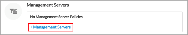
- For Releases 11.1.1 and later, to update management server policies for NTP, SNMP, syslog, and TACACS+, or to add a new management server policy, click + Management Servers. For more information, see Configure Management Servers.
- For Releases 11.3.1 and later, to create a user management policy or associate an existing user management policy with the master profile to add and manage VOS device users, click + User Management. For more information, see Manage VOS Users.

- For Releases 11.3.1 and later, to apply different services templates to the devices in a master profile for redundant devices:
- Go to Configure > Profiles > Master Profiles, and select a master profile for redundant devices.
- In the Edit Master Profile screen, click Profile > Others.
- Under Director Service Templates, click the Service Template box. The Director Service Templates screen displays the tenant's current service templates.
- Click + Service Templates in the lower right corner of the screen. The Choose Service Template screen displays the available service templates.
- Select one or more service templates, and then click Add. The templates are added to the Director Service Templates screen. By default, the service templates are added to both the primary and secondary devices in the redundant configuration. Note that the Appliance Type column displays only when you are editing a master profile for redundant devices.
- Click Sync Service Templates to synchronize service template bind data variable updates on a Concerto node. The service templates attached to the master profiles exist on Versa Director and any service template variable changes in Concerto must be in sync with Director. If service templates have new variables and values are not set, the publishing process fails.

- To apply the service template to only one of the redundant devices, click the drop-down list and then select either the Primary or Secondary device in the pair.

Clone the Default Basic Master Profile
You can create a new basic master profile by cloning one of the default basic master profiles, changing the configuration objects as needed, and saving the new basic master profile with a unique name. For example, you could create a new master profile to apply to hub appliances, and a second new master profile to apply to spoke appliances.

Enter a new name for the master profile, then click Submit. You can then edit the new basic master profile as needed. For information on the master profile screens, see Add a Standard Master Profile, below.
Add a Standard Master Profile
To add a standard master profile:
- In Tenants view, select the name of a tenant. If the default lifecycle is not the Configure lifecycle, select Configure in the left menu bar. The Configure screen displays.

- To create a new master profile of type Standard, click Configure > Profiles > Master Profiles > Standard, and then click + Standard.

The New Master Profile screen displays.

- In the Name field, enter a name for the new master profile.
- In the Solution Tier field, select a Versa licensing solution tier.
- For Releases 11.2.1 and later, in the Scope field, select if the master profile is for single tenant, multitenant, or subtenant. By default, Single Tenant is selected.
- Click Next. The Subprofiles tab displays.
- Click + Profile to add a subprofile to the master profile. You can create a new subprofile or reuse an existing one.

Reuse an Existing Subprofile
To reuse an existing subprofile in a new master profile:
- In New Master Profile > Subprofiles tab, click Choose Existing. The Choose Subprofiles screen displays.

- Select one or more existing subprofiles to use in the new master profile.
- Click Add.
Create a New Subprofile
To create a new subprofile to use in a new master profile:
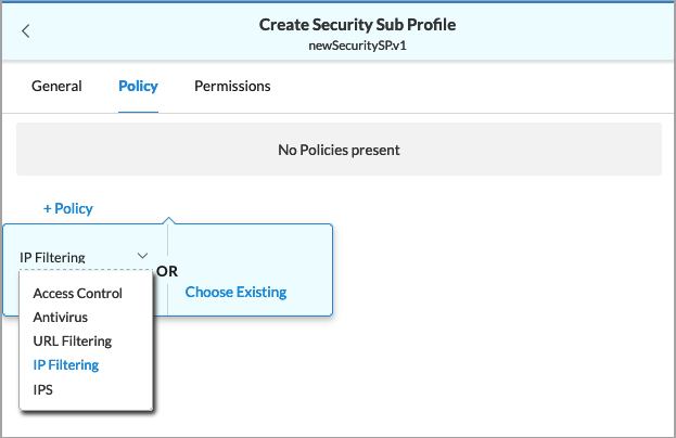
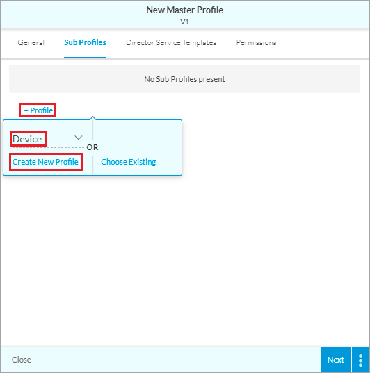
- In the New Master Profile > Subprofiles tab, click + Profile. The following popup window displays.

- Click the down arrow, select a profile type. The profile types are Security, Application, Device, Network Services, Topology, and, for Releases 11.3.1 and later, System.
- Click Create New Profile. The Create Type Subprofile screen displays. The following screenshot shows the Create Security Subprofile screen.

- Enter a name for the subprofile.
- Select the Policy tab or click Next. The Policy screen displays.
- Click + Policy to create a new policy or to reuse an existing one.

Reuse an Existing Policy
To reuse an existing policy:
- Click Choose Existing. The Choose Policies screen displays.
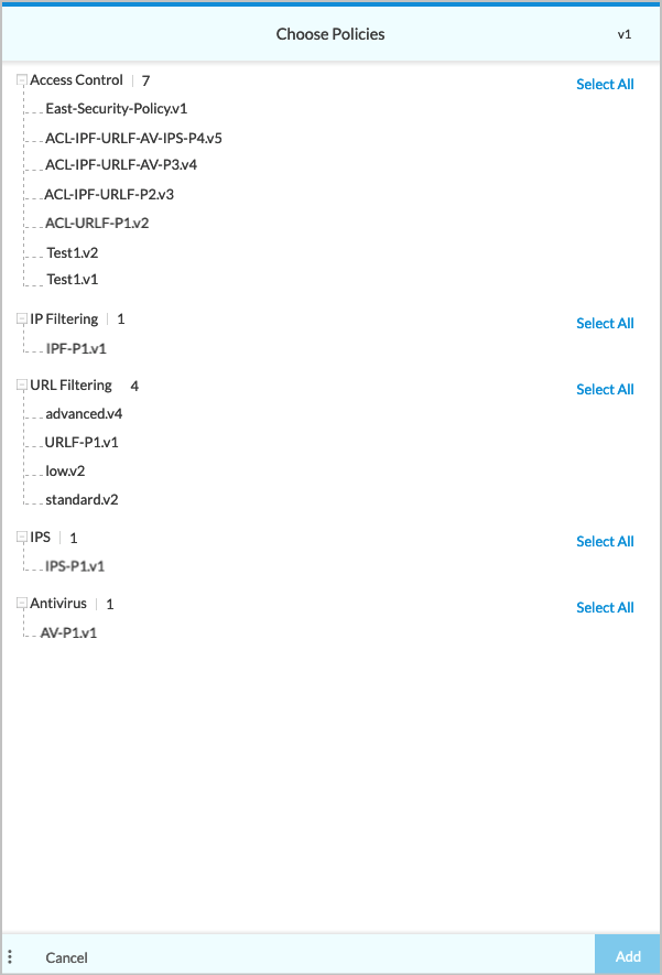
- Select one or more existing policies.
- Click Add.
Create a New Policy
To create a new policy:
- Select a policy type, and then click Create New Policy.
The Create Policy screen displays, and the General tab is selected. The following screenshot shows the Create IP Filtering Policy screen.
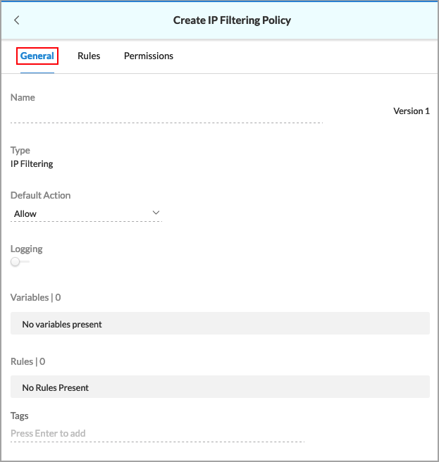
- Enter a name for the new policy.
- Click Next. The Rules tab displays. You can create a new rule or reuse an existing one.

- Click Add Rule.

Reuse an Existing Rule
To reuse an existing rule:
- Click Choose Existing Rule. The Choose Rules screen displays.

- Select one or more existing rules.
- Click Add.
Create a New Rule
To create a new rule:
- Click Create New. The Create Rule screen displays. The following screenshot shows the Create IP Filtering Rule screen.

- Enter a name for the rule.
- Click Next. The Criteria tab displays. In the Criteria Type field, enter information for the following fields.

Field Description Address Group Click in the field to the right of Address Group and select a group. You can select multiple address groups. Location 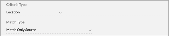
Click in the field to the right of Location, and then select a location. Then, in the Match Type field, select a match type:
- Match Only Source
- Match Only Destination
- Match Source or Destination
- Match Source and Destination
Reputation Click in the field to the right of Reputation, and then select one or more reputations. - Click Next. The Actions tab displays.

- In the Action field, select an action:
- Drop Packet
- Drop Session
- Allow
- Alert
- Reject
- Click Save.
Configure a Multitenant Standard Master Profile
For Releases 11.2.1 and later.
A multitenant master profile allows you to create multitenant appliances for a provider organization. You can create new subtenants and you can attach existing subtenants while publishing the provider organization appliance that uses the multitenant master profile. Appliances are automatically created in the subtenants associated with the provider appliance that uses a multitenant master profile.
To configure a multitenant standard master profile:
- Configure a standard multitenant with the scope Multitenant. Go to
- Go to New Master Profile > General.

- Enter a name for the profile.
- Select the solution tier.
- In the Scope field, select Multitenant.
- Click Next.
- Go to New Master Profile > General.
- Configure a device subprofile to add LAN Interfaces for the subtenants you want to onboard.
- Go to New Master Profile > Subprofiles, click + Profile, select Device, and then click Create New Profile.
- In Create Device Subprofile > General, enter a name for the subprofile.

- Click Next.
- In the Policy tab, click + Policy, select Interface, and then click Create New Policy. The Create Interface Policy screen displays.

- In Create Interface Policy > General, enter a name for the interface policy.

- Click Next. The Interfaces tab displays.

- Click Add Interface and then click Create New. The Create Interface screen displays. You can also choose an existing interface.
- The Create Interface screen displays.
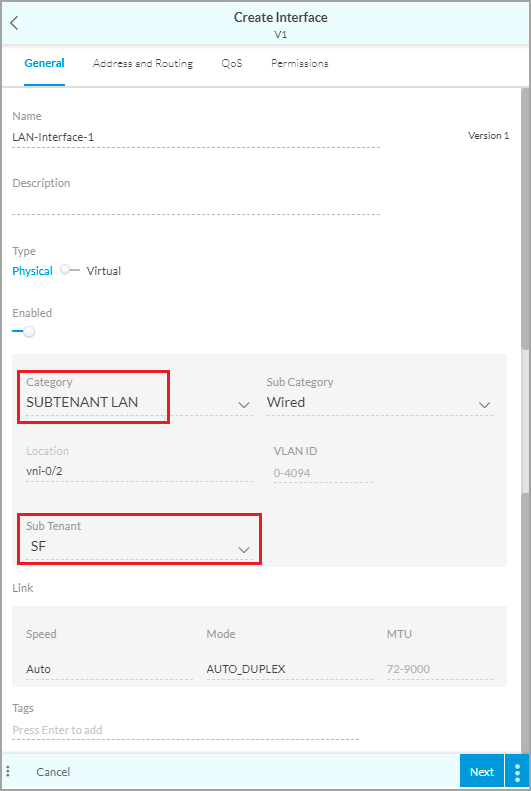
- Enter a name for the interface.
- In the Category field, select Subtenant LAN. Note that to create a LAN for the provider organization, select LAN.
- In the Subtenant field, select the subtenant for which you are creating the subtenant LAN interface.
- Enter other required information.
- Click Next.
- The Address and Routing tab displays.

- Enter the IPv4 address for the LAN interface.
- Select the VPN of the tenant in the VPN Name field. The VPN of the tenant you selected in the General tab is displayed by default.
- Click Next
- Enter other information, if required.
- Save the subtenant LAN interface. The interface that you added is displayed under subtenant LAN. For example:

- Repeat this step for other subtenant LANs.
- Go to New Master Profile > Subprofiles, click + Profile, select Device, and then click Create New Profile.
- Create a Topology subprofile to add a VPN policy and VPN instances to associate subtenant VPNs with the standard master profile.
- In New Master Profile > Subprofiles, click + Profile. Then select Topology, and click Create New Profile. The Create Topology Subprofile screen displays.
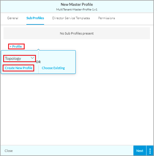
- In Create Topology Subprofile > General, enter a name for the subprofile.

- Click Next.
- In the Policy tab, click + Policy, select VPN and click Create New Policy.

- In Create VPN Policy > General, enter a name for the VPN policy.

- Click Next.
- In the VPN Instances tab, click Add VPN Instance > Create New. To select existing VPN instances, click Choose VPN Instance.

- Select Create VPN Instance > General.
- Enter a name for the VPN instance for the tenant.
- Under VPN, select the subtenant for which to create VPN instance.
- Select the name of the VPN connection. The VPN connection of the subtenant selected is displayed by default.
- Enter other required information.
- Click Next and save the VPN instance. The VPN instance displays in the VPN Instances screen.

- Repeat this step for all subtenant VPNs.
- Click Next. In the Permissions tab, set the permissions.
- Save the VPN Policy. The VPN policy displays in the Policy tab.

- Click Next. In the Permissions tab, set the permissions as required and then save the Topology subprofile.

- In New Master Profile > Subprofiles, click + Profile. Then select Topology, and click Create New Profile. The Create Topology Subprofile screen displays.
- Deploy the appliance associated to the standard master profile. When you publish, Concerto creates a subtenant appliance for each of the subtenants. For more information, see Concerto Deploy Lifecycle Overview.
Configure a Subtenant Standard Master Profile
For Releases 11.2.1 and later.
You can use subtenant standard master profile to configure services such as security, traffic steering, and application QoS for a subtenant. You can create application and security subprofiles only for a standard master profile.
To configure a subtenant standard master profile:
- Go to New Master Profile > General.

- Enter a name for the profile.
- Select the solution tier.
- In the Scope field, select subtenant.
- Click Next.
- In the Subprofiles tab, click + Profile, select Application or Security, and then click Create New Profile. Application and Security are the only subprofile options available for a subtenant standard master profile.

- Enter other required information.
- Save the subtenant standard master profile.
- Deploy the appliance associated to the standard master profile. For more information, see Concerto Deploy Lifecycle Overview.
Supported Software Information
Releases 10.2.1 through 12.2.2 support all content described in this article, except:
- Release 11.2.1 adds support for a new default basic master subtenant profile, Default-Basic-MP-Sub-Tenant, and for multitenancy configuration in the Default-Active-Active and Default-Basic-MP basic master profiles.