Deploy a VOS Branch in AWS Using Transit Gateway
For supported software information, click here.
This article describes how Versa Operating SystemTM (VOSTM) provides security and SD-WAN connectivity to AWS-hosted applications and application traffic in the Virtual Private Cloud (VPC) for on-premises sites and SASE users using the AWS transit gateway. The AWS transit gateway connects VPCs to on-premise networks through a central hub. For more details, see the AWS documentation at https://aws.amazon.com/transit-gateway.
Topology
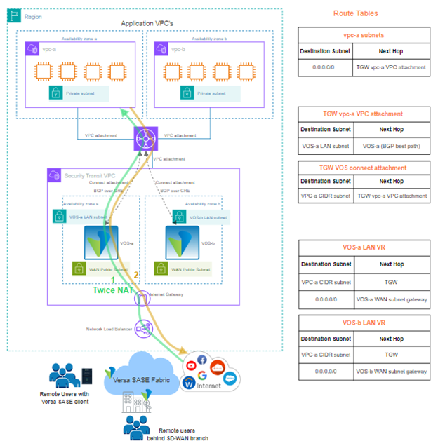
The AWS topology for this implementation is shown below.

In this topology, two VOS EC2 instances are deployed in a dedicated VPC, called the Security Transit VPC. Within the VPC, the EC2 instances can be deployed in the same or different availability zones in the AWS region.
AWS Configuration
- In the VPC section of the AWS console, create a new transit gateway service.

- Create a new security transit VPC, and then deploy two Versa EC2 instances:
- The EC2 instances can be placed in different availability zones or the same availability zone.
- In AWS, a subnet belongs to an availability zone, so if the VOS instances are in the same availability zone, then a single LAN subnet can be used for the LAN eni network interface of both VOS EC2 instances. The same applies for the WAN and management subnets.
For more information on how to configure the Versa EC2 instances in AWS, see Deploy a VOS Branch Using an AWS Marketplace Image through AWS Portal.
- Create a new VPC attachment to connect the security transit VPC to the transit gateway. Ensure that the application VPCs are also connected to the transit gateway using VPC attachments.

- Create a new transit gateway connect attachment. The connect attachment is used to establish a connection between a transit gateway and the VOS virtual appliances.

- Under the Transit Gateway Connect attachment, configure two connect peers. This is required to setup the GRE tunnel and BGP peering from the AWS transit gateway to the VOS EC2 instances.

- For Peer GRE Address, enter the LAN interface of the VOS EC2 instance.
- For each VOS instance, two BGP peering neighbors are created.
- After you enter the connect peer details, AWS generates the IP address for the BGP peers from the CIDR block provided. Retrieve the BGP peer IP addresses from the connect peers in the transit gateway connect attachment in the AWS console.
- Create the the following three new transit gateway route tables, associations, and propagations.
Name Associations Propagations TGW-VOS TGW VOS connect attachment TGW vpc-a VPC attachment TGW vpc-b VPC attachment TGW-vpc-a TGW vpc-a VPC attachment TGW VOS connect attachment TGW-vpc-b TGW vpc-a VPC attachment TGW VOS connect attachment In this topology, the following CIDR blocks are assigned to the following VPCs and on-premises site:
-
Security transit VPC – 10.53.0.0/16
-
vpc-a VPC – 10.51.0.0/16
-
vpc-b VPC – 10.52.0.0/16
-
on-prem site – 192.172.0.0/24
-
The following sections show the route tables for the transit gateway attachment circuits.
TGW-VOS (Connect Attachment)
The following route table displays the routes in the TGW connect attachment from the VOS EC2 instances. The CIDR block subnet routes vpc-a and vpc-b are propagated from the VPC attachment circuits.

TGW-vpc-a (VPC Attachment)
The following route table displays the routes in the TGW vpc-a attachment route table. The routes include the default route and the on-premise routes that are propagated from the TGW VOS connect attachment. These are BGP learned routes from the VOS-a and VOS-b instances.

TGW-vpc-b (VPC Attachment)
The following route table displays the routes in the TGW vpc-b VPC attachment route table. The routes include the default route, and the on-premise routes are propagated from the TGW VOS connect attachment. These are BGP learned routes from the VOS-a and VOS-b instances.

Versa Director Configuration for VOS
You must perform the following configuration for VOS in the active-active deployment mode.
To create an active-active template using the Director workflow:
- In Director view, select the Workflows tab in the top menu bar.
- Select Templates > Templates in the horizontal menu bar.
- Click the
Add icon to create a new template.
- Click step 1, Basic.
- In the Redundant Pair section, enter information for the following fields. For more information, see Create and Manage Staging and Post-Staging Templates.
- Select Enable. Do not select the VRRP or Cloud CPE option.
- In the Redundant Pair Type drop-down, select Active-Active.
- Enter the Redundant Template Name.

Use static IP address for the LAN interface of the VOS device to avoid a DHCP-learned default route in the LAN-VR of the VOS. The default route must be generated because of the split tunnel configuration made in device workflows.
- Click step 3, Tunnels to create the split tunnel for internet access and a site-to-site tunnel to AWS. Select the GRE as the tunnel protocol, and enable BGP over the GRE tunnel.

- Enter the GRE endpoints and BGP peer IP addresses in the bind data screen while creating the device in Workflows. For more information, see Configure Basic Features. Retrieve the BGP peer IP addresses from the connect peers in the transit gateway connect attachment in the AWS console.
- For traffic from internet to AWS-hosted applications, there must be a CGNAT policy for Twice NAT (source NAT and destination NAT).
- Configure DNAT using the workflow template. The workflow creates the DNAT pool and DNAT rule. The IP address 10.51.1.50 is the real IP address of the application in vpc-a in this topology.

- To create a new SNAT pool, in Director view, select the Configuration > Services > CGNAT in the left menu bar. For more information, see Configure CGNAT.
- Select the Pools tab, and then click the
 Add icon.
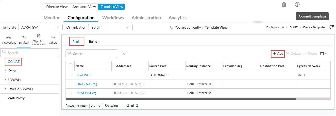
- In the Add CGNAT Pool popup window, select the IP Address tab, and then add the VOS device LAN IP address in the range as specified below. Specify the LAN routing instance.

- In the CGNAT home screen, select the Rules tab, and then select a rule.
- In the Edit CGNAT Rule popup window, click NAT Mode and select Twice-Dynamic-NAT-44, then click Source Pool and select SNAT-NAT-cfg.

Instead of modifying the workflow-generated DNAT rule, it is recommended that you clone the existing DNAT pool with a new name and higher precedence value (greater than 100) so the default workflow created rule is not matched.
- Configure DNAT using the workflow template. The workflow creates the DNAT pool and DNAT rule. The IP address 10.51.1.50 is the real IP address of the application in vpc-a in this topology.
- Verify the status of the BGP neighbors from the Director Monitor page.

Traffic Flow Use Cases
The AWS topology covers the following use cases:
- North-South traffic flow
- Remote SD-WAN branch site and/or SASE users to AWS-hosted applications
- AWS-hosted applications to remote sites and/or SASE users
- Outbound internet access for AWS-hosted applications
- Inbound internet access for AWS-hosted applications
- East-West traffic flow
- Application VPC to VPC traffic within AWS
North-South Traffic Flow Use Case
Remote SD-WAN branch site and/or SASE users to AWS-hosted application

- In the forward direction, VOS-a instance sends traffic to the transit gateway based on the vpc-a subnet route learnt through BGP from the transit gateway. In the transit gateway, the connect attachment route table lookup happens for the vpc-a subnet, and the traffic is sent to vpc-a over the VPC attachment.
- The return traffic also follows the same symmetric path. The vpc-a subnet route table has a default route pointing to the transit gateway VPC attachment. In the transit gateway, a route lookup happens in the vpc-a VPC attachment route table, and the traffic is forwarded to the VOS-a instance. The VOS-a instance is chosen because it advertises all of its routes to the transit gateway with a lower BGP path metric (lower AS path) compared to the VOS-b instance.
AWS-hosted applications to remote SD-WAN branch site and/or SASE users

- In the forward direction, the traffic flows through the transit gateway using the default route in the vpc-a subnet route table. In the transit gateway, a route lookup happens in the vpc-a attachment route table, and the traffic is forwarded to the VOS-a instance. The VOS-a instance is chosen because it advertises all its routes to the transit gateway with a lower BGP path metric (lower AS path) compared to the VOS-b instance.
- The return traffic also follows the same symmetric path. The VOS-a instance sends the traffic to the transit gateway based on the vpc-a subnet route learned through BGP from the transit gateway. In the transit gateway, a route lookup happens in the vpc-a attachment route table, and the traffic is forwarded to the VOS-a instance.
Outbound internet access for AWS-hosted applications

- In the forward direction, traffic flows through the transit gateway using the default route in the vpc-a subnet route table. In the transit gateway, a route lookup happens in the vpc-a attachment route table and the traffic is forwarded to the VOS-a instance. The VOS-a instance is chosen because it advertises all its routes to the transit gateway with a lower BGP path metric (lower AS path) compared to the VOS-b instance. The VOS-a instance does a source NAT with its WAN IP address and forwards the traffic to the Internet Gateway (IGW).
- The return traffic also follows the same symmetric path. The VOS-a instance sends traffic to the transit gateway based on the vpc-a subnet route learned through BGP from the transit gateway. In the transit gateway, a route lookup happens in the connect attachment route table for the vpc-a subnet, and the traffic is sent to vpc-a over the VPC attachment.
Inbound internet access for AWS-hosted applications
- In the forward direction, the load balancer chooses the VOS-a instance for the traffic session. The session traffic goes to the VOS-a instance over the WAN interface. A twice-NAT policy is applied on the traffic flow where the destination IP address is modified to the application’s real IP address, and the source IP address is modified to the VOS-a LAN address. The VOS-a instance then sends the traffic to the transit gateway based on the vpc-a subnet route learnt through BGP from the transit gateway. In the transit gateway, a route lookup happens in the connect attachment route table for the vpc-a subnet and the traffic is sent to vpc-a over the VPC attachment.
- The return traffic also follows the same symmetric path. The vpc-a subnet route table has a default route pointing to the transit gateway VPC attachment. In the transit gateway, a route lookup happens for the VOS-a LAN IP address and the traffic is forwarded to the VOS-a instance. Due to the Twice-NAT policy applied, VOS-a replaces the source IP address and destination IP address with the original addresses and forwards the traffic to the Internet Gateway (IGW).
Note:
- You can have a network load balancer with a public IP address that monitors the VOS WAN interfaces for redundancy.
- The network load balancer can forward the traffic session to any of the two VOS instances.
- Apply source NAT to keep the reverse traffic symmetric through the same VOS instance that handled the forward flow.
- For the network load balancer, you must configure a web proxy port for the VOS instances on the WAN address for the AWS target group response. For more information, see VOS High Availability in AWS Using Gateway Load Balancer.
East-West Traffic Flow Use Case
Application VPC to VPC traffic within AWS

- In the forward direction, the traffic flows through the transit gateway using the default route in the vpc-a subnet route table. In the transit gateway, a route lookup happens in the vpc-a attachment route table and the traffic is forwarded to the VOS-a instance. The VOS-a instance is chosen because it advertises routes with a lower BGP path metric (lower AS path) compared to the VOS-b instance. The VOS-a instance then looks up its routing table for the vpc-b subnet that is learned from the transit gateway using BGP. The traffic is sent back to the transit gateway connect attachment. A route lookup for the vpc-b subnet sends the traffic towards the destination VPC using the VPC attachment circuit from the transit gateway.
- In the reverse direction, the traffic flows symmetrically and the same as described in the forward direction.
Supported Software Information
Releases 22.1.4 and later support all content described in this article.