VOS High Availability in AWS Using Gateway Load Balancer
For supported software information, click here.
This document describes the use of the AWS Gateway Load Balancer to provide high availability (HA) to the Versa Operating SystemTM (VOSTM) EC2 instances in AWS. The Gateway Load Balancer service from AWS provides redundancy to third party virtual appliances like the VOS software. For more details, see the AWS documentation at https://aws.amazon.com/elasticloadba...load-balancer/.
Topology
The AWS topology for this implementation is shown below.

In this topology, two Versa VOS EC2 instances are deployed in a dedicated VPC, called the Security Transit VPC. Within the VPC, the EC2 instances can be deployed in the same or different availability zones in the AWS region. The application VPCs can belong to the same AWS account as the Security Transit VPC, or they can be in different AWS accounts.
This topology can be used to provide SD-WAN and security firewall services for the North-South traffic flowing between the Application VPCs and remote branch/SASE users and the internet using the Versa SD-WAN network. The East-West traffic within the Application VPC, and between Application VPCs, can also be protected by the Versa VOS EC2 instances.
Note that in this architecture, VPC peering is established between the Application VPCs and the Security Transit VPC. There are limits on how many VPC peerings a VPC may have, so this can scale for a smaller setup where there are only a few Application VPCs. For larger networks, it is recommended to deploy the VOS using AWS Transit Gateway.
AWS Configuration
- Create a new security transit VPC and deploy two Versa EC2 instances:
- The EC2 instances can be placed in different availability zones or the same availability zone. If all the application VPCs are in the same region, then the VOS EC2 instances can also be in the same availability zone because there is no benefit of placing the VOS instances in different availability zones.
- There are additional costs from AWS related to traffic that flows between availability zones.
- In AWS, a subnet belongs to an availability zone, so if the VOS instances are in the same availability zone, then a single LAN subnet can be used for the LAN eni network interface of both the VOS EC2 instances. The same applies for the WAN and management subnets as well.
- In the EC2 section of the AWS portal, create a new target group or type IP addresses. Select the GENEVE protocol. The Health check protocol can be the default value of TCP port 80, or you can choose any other non-default port number.

- Under Register Targets, add the IP address of the LAN interface of the VOS EC2 instance.

- In the EC2 section of the AWS portal, create a new Load Balancer of type Gateway Load Balancer.

- In the Load Balancer configuration, select the security transit VPC, and then add the LAN subnet of the VOS EC2 instances in the required availability zones. Attach the target group to the load balancer. The status of the targets in the target group will show as unhealthy because VOS is not yet configured to respond to the health check ports.

Note: If the EC2 instances are in different availability zones, then the cross-zone load balancing setting should be enabled under the load balancer settings. This is done after the load balancer is created by editing the load balancer attributes.
- In the VPC section of the AWS portal, create a new Endpoint Service. Select Gateway as the load balancer type, and then add the load balancer. After creation, make a note of the service name.

- In the application VPCs, create a new subnet (referred to as GLB-subnet in the topology diagram) in all the availability zones where the gateway load balancer service should be available.
- The gateway load balancer endpoint should be created in the application VPCs. You do this by going to the VPC section of the AWS portal and creating a new Endpoint. Select the type as Endpoint services that use NLBs and GWLBs. Enter the service name and add the GLB-subnet created in the previous step. If the endpoint service was configured to manually accept the connection, then go the endpoint service and accept the connection.

- The route tables of the application VPC subnets should be updated so that the default route points to the gateway load balancer endpoint.
- Under the VPC section, go to the VPC Peering option, and create a new VPC peering from each of the application VPCs to the security transit VPC.
- The CIDR block of the security transit VPC should be added to the routing table of the application VPC subnets with next hop pointing to the corresponding VPC peering endpoint.
Note: If intra-VPC traffic across subnets should be inspected by the VOS, then add specific subnet routes to point to the Gateway Load Balancer. - The routing table of the VOS LAN subnet should have an entry for the CIDR block of the application VPC subnets with next hop pointing to the corresponding VPC peering endpoint.
- Repeat steps 7 through 12 for the all the application VPCs.
Versa Director Configuration for VOS
The below configuration is done for VOS in Active-Active deployment mode.
- In Director, go to Configuration > Services > Web Proxy. On each of the VOS instances, configure the web proxy to listen on the port that is configured in the target group. The mode should be set to Explicit, followed by the LAN IP address of the VOS instance, LAN routing instance, and port number.

Note: For added security, a class of service L3/L4 policy can be configured on the VOS to only allow the Load Balancer Target group source IP address on destination port 80.
- Go to Configuration > Networking > Interfaces. Create a GENEVE tunnel interface on each of the VOS instances. Under the Interface type Tunnel, select “geneve” from the drop-down menu.


To get the destination IP address to be configured, go to the AWS portal and search under Network Interfaces in the EC2 section using interface type gateway_load_balancer. The VNI ID should be set to 0 and the routing instance should be set to be the LAN routing instance. In the sub-interface section, configure any /31 or / 32 IP address. This IP subnet is only used for setting the next hop for static routes in the VOS configuration. It is not used for ARP resolution, so this IP subnet will not be configured on the AWS side.
- If Cross-zone load balancing has been enabled, then configure a second GENEVE interface for the second zone.
- Go to Configuration > Networking > Virtual Routers. Add the GENEVE interfaces in the LAN routing instance.

- Go to Configuration > Others > Organization > Limits. Add the interfaces in the organization limits configuration.

- Go to Configuration > Networking > Zones. Create a new traffic zone and add the GENEVE interfaces in it.

- Go to Workflows > Template tab > Static Routes. Add a static route for the CIDR block of the application VPC pointing to the gateway of the VOS LAN subnet, which is the first IP address in the subnet. If the VOS instances are in different availability zones, then also add a static route for the LAN subnet of the peer VOS instance so that the VOS can respond to health probes of the Load Balancer coming from this subnet.

In the above example, since variables are used in the next hop field, ensure that the device bind data variables under Workflow devices have these values updated. The last subnet has a variable for the prefix of the peer VOS LAN subnet which is in a different AZ. Note the next hop address variable is the same, since the next hop IP address is the same for all the routes.
Note: After this step, the status of the target group in AWS should be marked as Healthy.
- For traffic from on-premise SD-WAN sites and remote SASE users to AWS hosted applications, a CGNAT policy is required to Source NAT the traffic with the IP address of the VOS LAN interface to keep the traffic flow symmetric.
- Go to Configuration > Services > CGNAT. Create a SNAT pool.


- Create a CGNAT rule (set precedence to 101 or greater if RFC1918 addresses are used in the Enterprise VPN network). In the destination, match the AWS application VPC subnets.

- Set the NAT mode to NAPT-44 and add the SNAT pool.

- Go to Configuration > Services > CGNAT. Create a SNAT pool.
- For inspection of traffic coming from the internet to the application VPC, i.e., when an application needs to be publicly hosted, a CGNAT policy is required for Twice NAT (Source NAT and Destination NAT).
- Create the SNAT pool and add the VOS LAN IP address in the range as specified below. Specify the LAN routing instance.


- In the CGNAT rule, set the NAT mode as Twice-Dynamic-NAT-44.

- Create the SNAT pool and add the VOS LAN IP address in the range as specified below. Specify the LAN routing instance.
Note:
- For the twice NAT configuration, it is recommended to configure DNAT from workflow templates. The workflow will create the DNAT pool and DNAT rule.
- The SNAT pool has to be created manually as shown above.
- In the DNAT rule created by the workflow template, modify the NAT mode to Twice Dynamic NAT-44, and add the source NAT pool.
Traffic Flow
The following use cases are covered in this topology:
- North-South traffic flow
- Remote branch site and/or SASE users to AWS hosted applications
- AWS hosted applications to remote sites and/or SASE users
- Outbound Internet access for AWS hosted applications
- Inbound internet access for AWS hosted applications
- East-West traffic flow
- Application VPC to VPC traffic within AWS
- Intra-VPC traffic within AWS
North-South Traffic Flow
Remote branch site and/or SASE users to AWS hosted application
- In the forward direction, the VOS applies a source NAT policy using its outgoing LAN interface IP address to keep the return traffic symmetric. The VPC peering is used to send traffic from the security transit VPC to the application VPC.
- The return traffic also uses the VPC peering and is kept symmetric due to the SNAT policy that changes the source IP of the traffic flow to the VOS LAN IP address.
Note that if the reverse route for the on-prem subnets in the application VPC points to the Gateway Load Balancer endpoint, then the return traffic is dropped. The Gateway Load Balancer does not support asymmetric traffic flows when the load balancer does not process the initial flow packet but the response flow packet is routed through the load balancer.

AWS hosted applications to remote branch site and/or SASE users
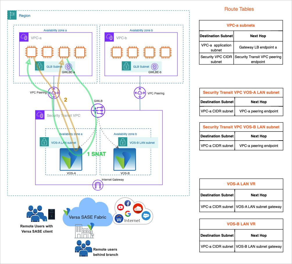
- In the forward direction, the traffic flows through the gateway load balancer endpoint. This is due to the default route in the application VPC subnets pointing to the gateway load balancer endpoint in the VPC. The gateway load balancer can send the traffic to any of the two VOC EC2 instances.
- The default behavior on the Versa SD-WAN enabled branch or Versa SASE cloud gateway is to always send the reverse traffic back to the same VOC EC2 instance from where the traffic flow originated. This ensures that the traffic is symmetrically flowing through the same VOS instance.
Note that in VPC-a subnet, a route lookup is done and the traffic is sent to the Gateway Load balancer endpoint. Here the traffic is encapsulated using the GENEVE protocol and then decapsulated by the VOS EC2 instance. The next route lookup then happens on the VOS EC2 instance.

Outbound Internet access for AWS hosted applications
- In the forward direction, the traffic flows through the gateway load balancer endpoint. This is due to the default route in the application VPC subnets pointing to the gateway load balancer endpoint in the VPC. The gateway load balancer can send the traffic to any of the two VOC EC2 instances.
- In the reverse direction, since the traffic is Source NAT’d to the VOS LAN IP address, the return traffic flows symmetrically through the same VOS EC2 instance that handled the forward flow.

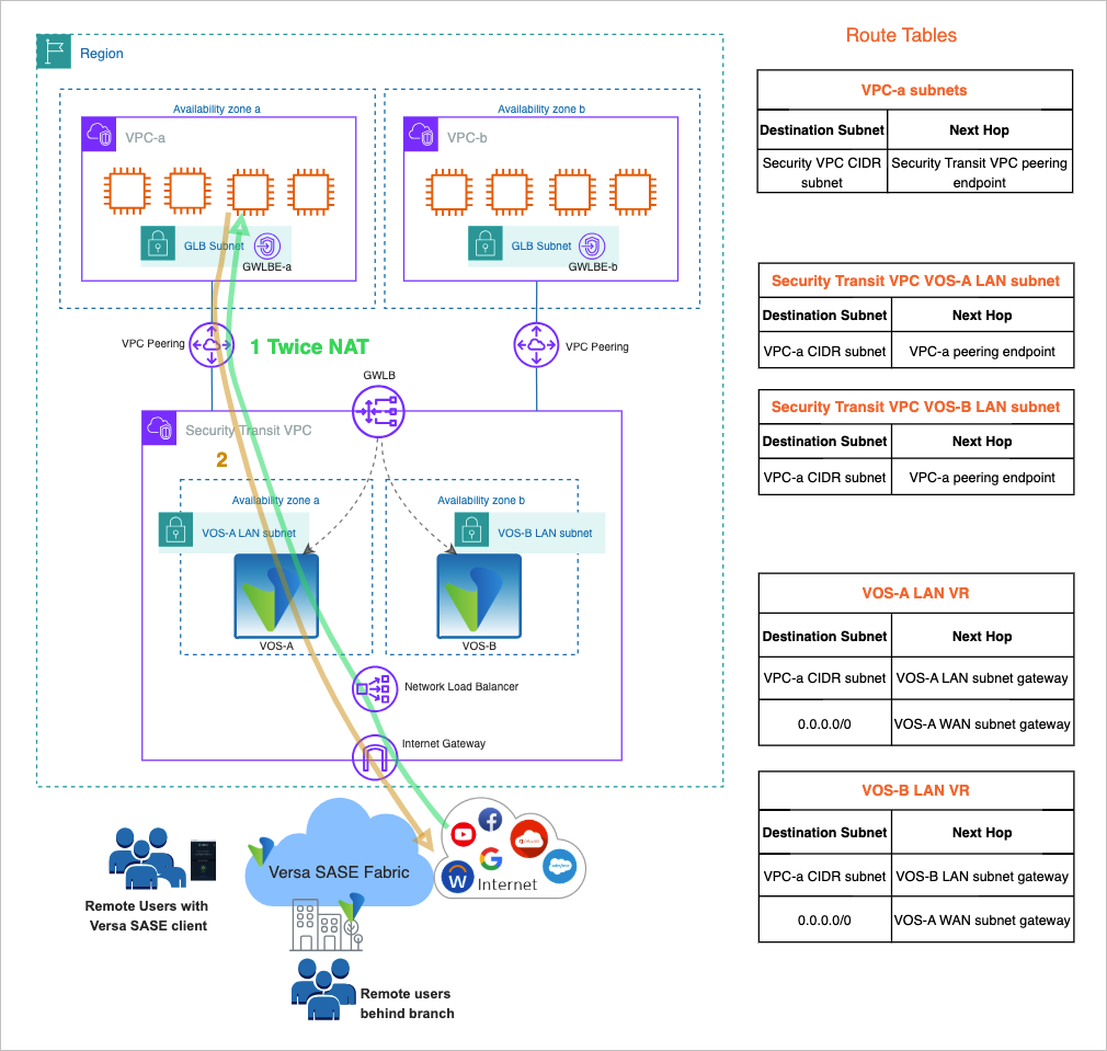
Inbound Internet access for AWS hosted applications
- In the forward direction, the traffic goes to the VOS using its WAN IP address. A Twice NAT (source and destination) is applied on the traffic flow. The destination IP address is modified to the application IP address and the source IP address is modified to the LAN interface IP address of the VOS.
Note:- It is common to have a Network Load Balancer with a public IP address which monitor the VOS WAN interfaces for redundancy.
- It will require a similar web proxy port configuration on the WAN address for the AWS Target group as described in this document for the Gateway Load Balancer.
- In the reverse direction, since the traffic is Source NAT’d to the VOS LAN IP address, the return traffic flows symmetrically through the same VOS EC2 instance that handled the forward flow.
East-West Traffic Flow
Application VPC to VPC traffic within AWS
- In the forward direction, the traffic flows through the gateway load balancer endpoint. This is due to the default route in the application VPC subnets pointing to the gateway load balancer endpoint in the VPC. The gateway load balancer can send the traffic to any of the two VOC EC2 instances.
- In the reverse direction, since the traffic is Source NAT’d to the VOS LAN IP address, the return traffic flows symmetrically through the same VOS EC2 instance that handled the forward flow.

Intra-VPC traffic within AWS
- In the forward direction, the traffic flows through the gateway load balancer endpoint. This is due to the route of the destination subnet pointing to the gateway load balancer endpoint in the VPC. The gateway load balancer can send the traffic to any of the two VOC EC2 instances.
- In the reverse direction, since the traffic is Source NAT’d to the VOS LAN IP address, the return traffic flows symmetrically through the same VOS EC2 instance that handled the forward flow.
Supported Software Information
Releases 22.1.4 and later support the GENEVE protocol required for the gateway load balancer implementation.