Configure SASE Site-to-Site Tunnels
![]() For supported software information, click here.
For supported software information, click here.
You can use site-to-site tunnels to encapsulate packets that are transmitted by a transport protocol. You can configure secure IPsec tunnels and generic routing encapsulation (GRE) tunnels from Versa Networks SASE gateways to data centers and to on-premises routers, firewalls, or SD-WAN appliances in an enterprise network. Site-to-site IPsec tunnels provide users with secure access to applications and workloads that are hosted in the cloud. The gateway device can be either a physical device or a cloud-based SD-WAN device. The remote (peer) device can be a cloud-managed service or a third-party device that supports IPsec tunnels.
Note: You must configure the following SASE rules, profiles, and settings in the following order:
- Configure users and user groups first, and then publish them to the gateway. For more information, see Configure User and Device Authentication.
- Configure site-to-site tunnels, as described in this article.
- Configure secure client access profiles and rules. For more information, see Configure SASE Secure Client-Based Access Rules.
You do not need to configure the remaining SASE rules, profiles, and settings in any particular order.
Configure Site-to-Site Tunnels
- Go to Configure > Settings > SiteToSite Tunnels.

The following screen displays.

- To customize which columns display, click to select or deselect the columns you want to display. Click Reset to return to the default columns settings.

- Click + Add to create a new tunnel. In the Add Site-to-Site Tunnel screen, enter information for the following fields in the Enter Type section.

Field Description Type Select the tunnel type:
- GRE
- IPsec (for Releases 11.4.1 and later)
Enabled Click the slider to enable the tunnel. Tunnel Type For the IPsec tunnel type, select the tunnel configuration to use:
- Policy-based (for Releases 11.4.1 and later)
- Route-based
Gateway Link (Group of Fields) - Versa Gateway
For an IPsec tunnel type, select a gateway, and then enter the IP address or FQDN of the remote device. For Releases 11.4.1 and later, optionally enter a remote public IP address or FQDN.

For the GRE tunnel type, select a gateway, then select a gateway circuit, and then enter the IP address of the remote device.

- Click Next. For the IPsec tunnel type, enter information for the following fields in the Enter IPsec Information section. For the GRE tunnel type, continue with the next step, Enter Address and Routing/Policy Configurations.

Field Description IKE (Group of Fields) - Version
Select the IKE version:
- V1
- V2
- V1 or V2
- Transform
Select the IKE transform type to use:
- 3des-md5
- 3des-sha1
- aes128-sha1
- aes128-md5
- aes256-sha1
- aes256-md5
- aes128-sha256
- aes256-sha256
- aes128-sha384
- aes256-sha384
- aes128-sha512
- aes256-sha512
- Diffie-Hellman Group (DH Group)
Select the Diffie-Hellman group to use:
- Diffie-Hellman Group 1—768-bit modulus
- Diffie-Hellman Group 2—1024-bit modulus. This is the default.
- Diffie-Hellman Group 5—1536-bit modulus
- Diffie-Hellman Group 14—2048-bit modulus
- Diffie-Hellman Group 15—3072-bit modulus
- Diffie-Hellman Group 16—4096-bit modulus
- Diffie-Hellman Group 19—256-bit elliptic curve
- Diffie-Hellman Group 20—384-bit elliptic curve
- Diffie-Hellman Group 21—521-bit elliptic curve
- Diffie-Hellman Group 25—192-bit elliptic curve
- Diffie-Hellman Group 26—224-bit elliptic curve
- No PFS
Default: Diffie-Hellman Group 2—1024-bit modulus
- DPD Timeout
Enter how long to wait for traffic from the destination peer on the tunnel before sending a dead-peer-detection (DPD) request packet.
Range: 10 through 180 seconds
Default: 30 seconds- Unit Type
Select the time units for how often to regenerate the IKE key, and then enter the time interval:
- Hours
- Minutes
- Seconds
- IKE Rekey Time
Enter how often to regenerate the IKE key. The value range depends on the units you select in the Unit Type field.
Range:
- 132 through 86400, for seconds
- 3 through 1440, for minutes
- 1 through 24, for hours
Default: 28800 seconds
IPsec (Group of Fields) - IPsec Transform
Select the IPsec transform type to use:
- esp-3des-md5
- esp-3des-sha1
- esp-aes128-ctr-sha1
- esp-aes128-ctr-xcbc
- esp-aes128-gcm
- esp-aes128-md5
- esp-aes128-sha1
- esp-aes128-sha256
- esp-aes128-sha384
- esp-aes128-sha512
- esp-aes256-gcm
- esp-aes256-md5
- esp-aes256-sha1
- esp-aes256-sha256
- esp-aes256-sha384
- esp-aes256-sha512
- esp-null-md5
- Perfect Forward Secrecy Group (PFS Group)
Select the Diffie-Hellman groups to use for PFS:
- Diffie-Hellman Group 1—768-bit modulus
- Diffie-Hellman Group 2—1024-bit modulus.
- Diffie-Hellman Group 5—1536-bit modulus
- Diffie-Hellman Group 14—2048-bit modulus
- Diffie-Hellman Group 15—3072-bit modulus
- Diffie-Hellman Group 16—4096-bit modulus
- Diffie-Hellman Group 19—256-bit elliptic curve
- Diffie-Hellman Group 20—384-bit elliptic curve
- Diffie-Hellman Group 21—521-bit elliptic curve
- Diffie-Hellman Group 25—192-bit elliptic curve
- Diffie-Hellman Group 26—224-bit elliptic curve
- No PFS. This is the default.
Default: No PFS
- Hello Interval
Enter the IPsec keepalive timeout, which is how often to send a Hello message to the peer to determine whether the peer is still up and operational.
Range: 0 through 36000 seconds
Default: 10 seconds
- Unit Type
Select the time units for how often to regenerate the IPsec key, and then enter the time interval:
- Hours
- Minutes
- Seconds
Default: Seconds
- IPsec Rekey Time
Enter how often to regenerate the IPsec key. The value range depends on the units you select in the Unit Type field.
Range:
- 132 through 86400, for seconds
- 3 through 1440, for minutes
- 1 through 24, for hours
Default: 28800 seconds
- Authentication
Select the authentication:
- Certificate Authentication
- PSK
- Local—PSK Authentication (Group of Fields)
For PSK authentication, enter information for the following fields:

Field Description Local (Group of Fields) - Identity Type
Select an identity type:
- FQDN
- IP address
- Value
Enter a value for the identity type:
- Email—Enter a valid email address.
- FQDN—Enter a valid FQDN.
- IP Address—Enter a valid IP address.
- Share Key
Enter the share key for the local devices. Remote (Group of Fields) - Identity Type
Select an identity type:
- FQDN
- IP address
- Value
Enter a value for the identity type: - Email—Enter a valid email address.
- FQDN—Enter a valid FQDN.
- IP Address—Enter a valid IP address.
- Share Key
Enter the share key for the remote devices. - Local—Certificate Authentication (Group of Fields)
For Certificate Authentication, enter information for the following fields:

- Certificate Name—Select a certificate name for both the local and remote devices.
- CA Chain—Select a CA chain for both the local and remote devices.
Click + Add New to add new certificates names and CA chains for the local and remote devices. Fore more information, see Configure SASE Certificates.
- Click Next.
- For the GRE tunnel type and for a route-based tunnel configuration for an IPsec tunnel type, enter information for the following fields in the Enter Address and Routing/Policy Configurations section, and then continue with Step 8. Note that Enter IPsec Information section is not applicable for GRE tunnel type. For the Policy-based tunnel configuration for an IPsec tunnel type, continue with Step 7.

Field Description Tunnel Virtual Interface IP Address Enter the tunnel virtual interface IP address. VPN Name Select the VPN through which the IP address is reachable. MTU (For Releases 11.4.1 and later.) Enter the maximum transmission unit size, in bytes, of the largest protocol data unit that the port can receive or transmit.
Range: 256 through 9000 bytes
Static Routes (Group of Fields) - + Add
Click to add a static route. Enter information for the following fields.
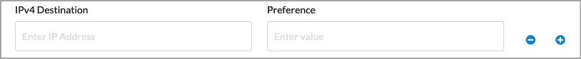
- IPv4 Destination—Enter the IPv4 destination address.
- Preference—Enter a preference value for the static route.
Range: 1 through 255
Default: None  Minus icon—Click to delete a static route entry.
 Plus icon—Click to add a static route entry.
Routing Protocol Select the routing protocol:
- EBGP
- None
If you select None, no further information is required. If you select EBGP, enter information for the following fields.
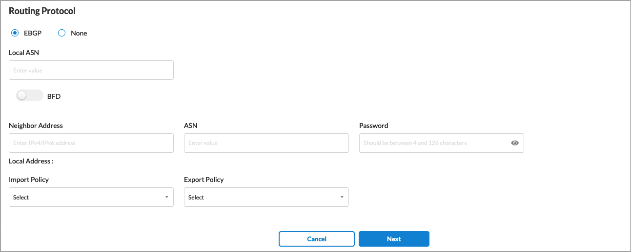
- Local ASN—Enter the local AS number.
- BFD—Click the slider to enable Bidirectional Forwarding (BFD).
- Neighbor Address—Enter the IP address of the peer device.
- ASN—Enter the AS number of the peer device.
- Password—Enter the password for the peer device.
- Local Address (Group of Fields)—
- Import Policy—(Optional) Select an EBGP import policy from the drop-down list.
- Export Policy—(Optional) Select an EBGP export policy from the drop-down list.
For information about creating import and export policies, see Configure SASE BGP Peer Policies
- (For Releases 11.4.1 and later.) For the policy-based tunnel configuration for an IPsec tunnel type, enter information for the following fields.

Field Description VPN Name Select the VPN through which the IP address is reachable. Policy Configurations (Group of Fields) - Protocol
Select a protocol:
- Any
- ICMP
- TCP
- UDP
- Source IP Address/Prefix
Enter the IPv4 source prefix. - Source Port
Enter the source port number.
Range: 0 through 65535
- Destination IP Address/Prefix
Enter the IPv4 destination prefix. - Destination Port
Enter the destination port number.
Range: 0 through 65535
- Precedence
If there are multiple matches for the policies, indicate the precedence level of the tunnel. A number closer to 0 indicates a higher priority.
Range: 0 through 512
- Click Next.
- In the Enter Name, Description, and Tags section, enter information for the following fields.

Field Description Name (Required) Enter a name for the tunnel. Description Enter a description for the tunnel. Tags Enter one or more tags for the tunnel. -
Click Save.
Supported Software Information
Releases 11.1.1 and later support all content described in this article, except:
- Release 11.4.1 adds support for policy-based IPsec site-to-site tunnels.