Configure SD-WAN Policy
![]() For supported software information, click here.
For supported software information, click here.
Normally, packets are routed based on entries in the routing table. To change how packets are routed, you configure SD-WAN policy. You can configure SD-WAN policy for Layer 2 traffic (for Releases 21.2.1 and later) and for Layer 3 traffic (for Releases 20.2 and later).
A policy consists of the following components:
- Policy name, which identifies the policy.
- Policy rules, which define the conditions for matching packets. A policy can have one or more rules, and the rules are evaluated in order until a match occurs. A rule can match traffic based on any combination of Layer 3 criteria (such as IP addresses and header fields, zones, and DSCP values), Layer 4 criteria (such as Layer 4 protocol and ports), and Layer 7 criteria. A rule can match individual applications and groups of applications. For Layer 2 SD-WAN policy, rules can also match Layer 2 criteria, such as MAC address and VLAN ID. For groups of application, a rule can match based on tags or attributes associated with the application (for example, FTP, SFTP and TFTP are tagged as file transfer applications). In a rule, you can define time schedules to taking the policy action.
- Enforcement criteria, which define the action to take on packets that match the rules and whether to log and monitor matching packets.
Each policy is specific to an organization (that is, a tenant). This means that each tenant on a multitenant branch device can control their path selection behavior independently.
To allow an SD-WAN policy to correctly process all traffic in an application flow, it uses application detection, which is always running on the VOS device, to inspect the first packet in a flow and to identify the Layer 7 application sending the flow.
To configure a policy, you do the following:
- Define a policy name
- Configure policy rules
- Configure application detection parameters
Configure Policy Names
To configure a policy, you first name the policy. Currently, each template can have only one access policy, and this policy is called Default-Policy. If desired, you can add a description for the policy, but you cannot rename it.
To add a description to a policy name:
- In Director view:
- Select the Configuration tab in the top menu bar.
- Select Templates > Device Templates in the horizontal menu bar.
- Select an organization from the left menu bar.
- Select a post-staging template in the main pane. The view changes to Appliance view.
- Or, to add a policy name description for a device's policy, select Devices > Devices in Step 1b and then select a device in the main pane.
- Select the Configuration tab in the top menu bar.
- For a Layer 2 SD-WAN policy:
- Select Services > Layer 2 SD-WAN > Policies in the left menu bar.
- Select the Policies tab in the horizontal menu bar. The main pane displays a list of configured policies.

- For a Layer 3 SD-WAN policy:
- Select Services > SD-WAN > Policies in the left menu bar.
- Select the Policies tab in the horizontal menu bar. The main pane displays a list of configured policies.

- Click the name of the policy. In the Edit Policies popup window, enter the description and tag for the policy.

- Click OK.
Configure Policy Rules for Layer 2 SD-WAN Policy
For Releases 21.2.1 and later.
In policy rules, you configure the conditions for matching packets of interest, and you also configure the forwarding and logging actions to take on the packets that match the conditions. To configure policy rules, you select an organization (that is, a tenant), and then you select one of the tenant's post-staging templates. Then you perform the following steps, which are described in the procedure below:
- Add a new rule (Steps 1 through 5).
- Configure a rule name (Step 6).
- Configure match conditions:
- Configure source address, source MAC address, source zone, and source site match criteria (Steps 7 through 14).
- Configure destination address, destination MAC address, destination zone, and destination site match criteria (Steps 15 through 20).
- Configure match criteria based on the contents of the IP packet header and VLAN ID, and set a time at which to apply the policy (Step 21).
- Configure application and SaaS application match criteria (Steps 22 through 31).
- Configure match criteria for URL categories (Steps 32 through 34).
- Define the users and user groups to which the rule applies (Step 35).
- Select the forwarding classes and loss priorities to match (Step 36).
- Select the actions to take on matching packets, including applying a forwarding and a logging profile (Step 37).
When you configure the match conditions for a policy rule, you configure each group of related rules on a single tab on the Add Rules popup window. All rule values that you configure on the same tab, and within the same pane on a tab, are processed as a logical OR function, and rule values that you configure on different tabs are processed as a logical AND function. For example, if you include multiple addresses in the source address field, any one of the addresses can fulfill the match criteria for that field. If you include multiple source addresses and if you also configure a source zone (on the same tab, but in different panes), the traffic must match one of the source addresses AND one of the source zone parameters.
To configure a policy rule:
- In Director view:
- Select the Configuration tab in the top menu bar.
- Select Templates > Device Templates in the horizontal menu bar.
- Select an organization in the left navigation bar.
- Select a post-staging template in the main panel. The view changes to Appliance view.
- Or, to configure a policy rule for a device's policy, select Devices > Devices in Step 1b and then select a device in the main pane.
- Select the Configuration tab in the top menu bar.
- Select Services > Layer 2 SD-WAN > Policies in the left menu bar. In the main pane, the Rules tab in the horizontal menu bar is selected, and the table displays a list of configured rules. To display more of the rule components, scroll the main pane horizontally.

- Click the
 Add icon to add a rule. The Add Rules window displays.
 - If you have already added one or more rules, the Add popup window displays.
- Select where you want to insert the policy rule, either at the beginning or end of the existing rules.

- If you select a rule and then click the Add icon, the Add popup window displays the following options:

- Select the order to insert the rule (at the beginning or end bottom of the existing rules, or before or after the selected rule).
- Click OK. The Add Rules popup window displays.

- Select where you want to insert the policy rule, either at the beginning or end of the existing rules.
- Select the General tab, and enter a name for the rule and a text description for the rule. Click Disabled to disable the rule after it is created.
- Select the Source tab to configure match criteria based on source addresses, source MAC addresses, source zone, source site names. These match criteria match traffic coming from ptvi (overlay) interfaces from the configured remote sites or zones.

- Click the Add icon in the Source Address pane, and then select the source address, source address group, or source address region of incoming traffic to match. For zones that you have configured for interfaces and networks, select the source zone to apply the rule to traffic coming from any interfaces or networks in the zone. Note that you cannot configure source zones for zones that you have configured for routing instances or for organizations. For information about configuring zones, see Configure Zones and Zone Protection Profiles.
-
Click + New Address to add a source address. In the Add Address popup window, enter information for the following fields.

Field Description Name (Required) Enter a name for the source address. Description Enter a text description for the source address. Tags Enter a keyword or phrase that allows you to filter the source address. This is useful when you have many addresses and want to view those that are tagged with a particular keyword. Type and Address/Prefix
(Required)Select the type of IP address to match and the value to match. The name of the Address/Prefix field changes depending on the value you select in the Type field.
- IPv4 (type);
IPv4 Address/Prefix (match)
Evaluate the address match using an IP address within the IPv4 prefix specified in the IPv4 Address/Prefix field. This is the default. - IPv4 Wildcard Mask (type);
IPv4 Wildcard Mask (match)

(For Releases 20.2.2 and later.) Enter a wildcard mask for an IPv4 address. The bits in the mask can be on (1) or off (0). Only the bits that are enabled in the mask are used to determine whether an IPv4 address matches. When a bit in a wildcard mask is on, that bit must match. When a bit in a wildcard mask is off, it is considered as a "don't care" bit and is disregarded for purposes of address matching. For example, the IPv4 address and mask 192.168.3.100/255.255.3.255 matches any IPv4 address 192.168.x.100, where, for x, the first 6 bits can be on (1) or off (0) and the last two bits must be on (11). Note that in a wildcard mask, at least one bit must be on.
You can configure overlapping wildcard addresses.
A single session can match a maximum of 16 wildcard addresses.
You can configure wildcard address objects individually or as part of address groups.
You cannot combine an address prefix (or range) match with wildcard addresses to match a source or destination address.
- IPv4 Range (type);
IPv4 Range (range)
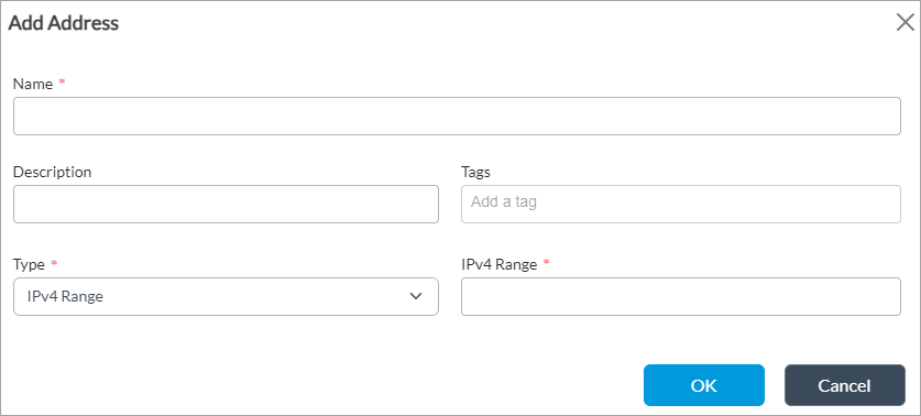
Evaluate the address match using an IP address within the IPv4 address range specified in the IPv4 Range field.
- IPv6 Address/Prefix (type);
IPv6 Address/Prefix (range)

Evaluate the address match using any of the IP addresses within the IPv6 address range specified in the IPv6 Address/Prefix field.
- FQDN (type);
FQDN (match)

Evaluate the address match using an IP address returned in a DNS query that resolves the fully qualified domain name (FQDN) into an IP address. The FQDN cannot contain any wildcard characters.
- Dynamic Address (type);
no range

(For Releases 22.1.3 and later.) Use a dynamic address object, which is a container for an IP address list that can change dynamically. Using dynamic addresses in a policy allows you to perform a configuration before the IP addresses are known, thus avoiding the need to update the configuration each time IP addresses are added or deleted. You typically configure dynamic address objects for hosts whose IP addresses may change later, for example, if you are performing a live migration of virtual machines (VMs) using the vSphere vMotion technology to migrate a VM from one cluster to another, which changes the IP address of the VM.
To configure a dynamic address object, issue the set orgs org-services tenant name objects addresses address object name dynamic-address CLI command.
To update the list of IP addresses associated with a dynamic address object without updating the configuration, issue the request orgs org-services tenant name objects dynamic-address add name tenant name address private-internet-IP address CLI command.
OK Click OK. - IPv4 (type);
- Click + New Address Group to add an address group. In the Add Address Group popup window, enter information for the following fields.

Field Description Name (Required) Enter a name for the address group. Description Enter a text description for the address group. Tags Enter a keyword or phrase that allows you to filter the address group. This is useful when you have many address groups and want to view those that are tagged with a particular keyword. Address Click the
 Add icon to select an address to add to the group.
+ New Address Click to add a new address to the group. In the Add Address popup window, enter a name, description, and tags for the address, select the IP address type (IPv4 or IPv6), and enter the IP address prefix. Address File Click the Add icon to select an address file. The address file contains IP addresses to add to the group.+ New Address File Click to upload a file containing IP addresses to the VOS device. In the Upload Address Files to Appliance popup, select the filename in the Filename field. The Appliance field displays the name of the VOS device, which is the name of the tenant's device. OK Click OK. - Click Source Address Negate below the Source Zone pane to block traffic to the selected source addresses instead of accepting it.
- Click the Add icon in the Source MAC Address pane, and then select the source MAC address. If no source MAC address is configured, create the source MAC address as follows:
- In Appliance view, select Configuration from the top menu bar.
- In the left menu bar, select Objects & Connectors > Objects > MAC Addresses. The MAC Addresses dashboard displays.

- Click the Add icon. In the Create MAC Address screen, enter the following information.

Field Description Name (Required) Enter a name for the MAC address, MAC Addresses (Group of Fields) - Addresses (Required)
Enter a MAC address. - Description
Enter a description for the MAC address.  Add icon
Click to add the MAC address. MAC Type Select a MAC type:
- Broadcast
- Multicast
Wildcard Mask (Group of Fields) - Masks (Required)
Enter a wildcard mask. For example, the wildcard mask in the screenshot above is 06:56:8a:ab:4f:02/ff:ff:00:ff:00:00. - Description
Enter a description for the wildcard mask.  Add icon
Click to add the MAC address. -
Click OK.
- In the Source Zone pane, click the Add icon, and then select the source zone of the traffic. A zone is a set of interfaces.
- In Source Site Name pane, click the Add icon and select the source sites to match.
- Click Source Location Negate to select any source locations except the configured source locations.
- (For Releases 22.1.2 and later.) Click the Add icon, and then select a custom geographic circle. A geographic circle consists of a point and the area enclosed by a circle drawn around that point. To configure a custom geographic circle, see Configure Custom Geographic Circles.
- Select the Destination tab to configure match criteria based on destination addresses, destination MAC addresses, destination zone, and destination site names.

- Click the Add icon in the Destination Address pane, and then select a destination address, destination address group, or destination address region of traffic that you want to match. You can add new addresses or address groups to the Destination Address pane, and you can negate destination addresses, in the same way as was done in the Source Address pane, as described above.
- Click the Add icon in the Destination Mac Address pane, and then select the destination MAC address. If no destination MAC address is configured, create the destination MAC address in the same way that you created the source MAC address in Step 12.
- Click the Add icon in the Destination Zone pane, and then select the destination zone of the traffic. A zone is a set of interfaces.
- Click + New Zone to add a zone. In the Add Zone popup window, enter information for the following fields. For zones that you have configured for interfaces and networks, select the destination zone to apply the rule to traffic going to any interfaces or networks in the zone. Note that you cannot configure destination zones for zones that you have configured for routing instances or for organizations. For information about configuring zones, see Configure Zones and Zone Protection Profiles.

Field Description Name (Required) Enter a name for the zone. Description Enter a text description for the zone. Tags Enter a keyword or phrase that allows you to filter the zone. This is useful when you have many zones and want to view those that are tagged with a particular keyword. Zone Protection Profile Select a zone protection profile. + Create Zone Protection Profile Click to create a zone protection profile. Log Profile Select a log profile. + Create Log Profile Click to create a log profile. Interface and Network Click to specify the interfaces and networks that are in the zone. In the Interfaces and Networks panes, select the interfaces and network that are in the zone. Click the Add icon to add interfaces or networks.OK Click OK. - In Destination Site Name pane, select the destination site to match. Click the Add icon to add destination sites.
- Click Destination Address Negate below the Destination Zone pane to block traffic to the selected destination addresses instead of accepting it.
- Click Destination Location Negate to select any destination locations except the configured destination locations.
- (For Releases 22.1.2 and later.) Click the Add icon, and then select a custom geographic circle. A geographic circle consists of a point and the area enclosed by a circle drawn around that point. To configure a custom geographic circle, see Configure Custom Geographic Circles.
- Select the Headers/Schedule tab to configure match criteria based on the contents of the IP packet header and to set a time at which to apply the policy. Enter information for the following fields.

Field Description IP (Group of Fields) - IP Version
Select the IP version:
- IPv4
- IPv6
- IP Flags
Select whether routers can fragment data packets: - Don't Fragment
- More Fragments
- DSCP
Click the
Add icon to add a differentiated services code point (DSCP) value.Range: 0 to 63
Default: None
TTL (Group of Fields) - Condition
Select the TTL condition to use for the match. The TTL is the number of hops that a packet can travel before it is discarded. It indicates the lifespan of a packet. The condition can be one of the following boolean values: - Equal to—TTL value must be equal to the specified value to trigger the security access rule
- Greater than or equal to—TTL value must be greater than or equal to the specified value to trigger the security access rule
- Less than or equal to—TTL value must be less than or equal to the specified value to trigger the security access rule
- Value
Enter the value for the TTL.
Range: 1 to 255
Default: None
Others (Group of Fields) - Schedules
Select a schedule to set the time during which the rule is in effect and now often the schedule recurs.
- + Schedule
Click to create a schedule. In the Create Schedule popup window, enter information for the following fields.

- Name (Required)—Enter a name for the schedule.
- Description—Enter a description for the schedule.
- Tags—Enter a keyword or phrase that allows you to filter the schedule name.
- Recurrence—Select Non-Recurring (for a one-time schedule), Daily, or Weekly.
- State Date, Start Time, End Date, and End Time (Required)—Enter or select the starting and ending date and time for the schedule. Then click the Add icon.
Then, click OK.
Services (Group of Fields) - Service List
Select the services to allow or block. Click the Add icon to select a service. The list includes predefined and custom services. A service is defined based on the destination address and port.- + New Service
Click to create a service. In the Add Service popup window, enter information for the following fields.

- Name (Required)—Enter a name for the service.
- Description—Enter a description for the service.
- Tags—Enter a keyword or phrase that allows you to filter the service name.
- Protocol (Required)—Click the Protocol button and select a protocol name in the Protocol field.
- Protocol Value (Required)—Click the Protocol Value button and enter a protocol value in the second Protocol Value field.
Range: 0 to 255
Default: None - Port Range—Click the Port Range button and the ports to use in the Port field, which can be a range of ports or individual ports.
Range: 24000 to 24500
Individual ports: 25000, 25001, or 25002
Default: None - Source/Destination—Click the Source/Destination button and enter a port number in the Source Port and Destination Port fields.
-
(For Releases 22.1.1 and later.) ICMP— Click the ICMP protocol to define a custom service object by ICMP values.
- Code—Enter the ICMP code. You can enter an individual value, a comma-separated list of values, or a range of values.
- Type—Enter the ICMP type. You can enter an individual value, a comma-separated list of values, or a value range of values (for example, 9-12).
Then, click OK.
VLAN IDs (Group of Fields) - VLAN ID List
Click the Add icon to add VLAN IDs to the list. If no VLAN IDs are configured, create the VLAN IDs as follows:
- In Appliance view, select Configuration from the top menu bar.
- In the left menu bar, select Object & Connectors > VLAN ID.
- Click the Add icon. In the Create VLAN ID screen, enter the following information.
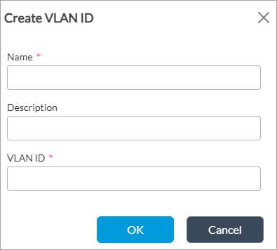
Field Description Name (Required) Enter a name for the VLAN ID. Description Enter a description of the VLAN ID. VLAN ID (Required) Enter the VLAN ID.
Range: 1 to 4094
Default: None
- Click OK.
- Select the Applications tab to configure matching criteria for applications and SaaS application groups.

- In the Applications table, click the Add icon and then select an application list from the predefined and custom applications. For more information about predefined and custom applications, see Configure NGFW.
- To add an application group, click + New Group. In the New Group popup window, enter a name for the group, a description, and tags.
- Click the Add icon and select applications to add to the group. You can click the Browse icon to display the available applications in the Application Browser window.

- Click OK.
- To add an application filter, click + New Filter. In the New Filter popup window, enter a name for the filter, select the desired filters, and click OK.

- To add an application, click + New Application. In the New Application popup window, enter information for the following fields.

Field Description Name (Required) Enter a name for the application. Description (Required) Enter a description for the application. Precedence (Required) Enter a value for the priority of the application.
Range: 0 to 65535
Default: None
Application Timeout Enter how long to wait before timing out the application, in seconds.
Range: 1 through 15999999 secondsDefault: None
Application Match based on IPs signature Click to match the IP address of the application. - In the Attributes tab, enter information for the following fields.
Field Description Family
Select the family to which the application belongs. Subfamily
Select the subfamily to which the application belongs. Risk
Select the risk level to assign to the application. A value of 1 indicates the lowest risk level, and a value of 5 indicates the highest. Productivity
Select a productivity level to assign to the application. Application Tags
Select one or more security, Layer 2 SD-WAN, and general tags to associate with the application. - Select the Match Information tab and click the Add icon. The Add Match Information popup window displays, enter information for the following fields.

Field Description Name (Required) Enter a name for the application match. Host Pattern Enter the host pattern to match. Protocol Value Enter the application's protocol name or number.
Range: 0 to 255
Default: None
Source Address Enter the IP address and mask of the source application. Destination Address Enter the IP address and mask of the destination application. Source Port (Group of Fields) Click to match the source ports of the application. - Value
Click to match a single source port of the application.
- Source Port Value
Enter the source port number.
Range: 0 to 65535
Default: None
- Range
Click to match a range of source ports of the application. - Low
For a range of source ports, enter the lowest port number.
Range: 0 to 65535
Default: None
- High
For a range of source ports, enter the highest port number.
Range: 0 to 65535
Default: None
Destination Port (Group of Fields) Click to match destination ports of the application. - Value
Click to match a single destination port of the application. - Destination Port Value
Enter the destination port number.
Range: 0 to 65535
Default: None
- Range
Click to match a range of destination ports of the application. - Low
For a range of destination ports, enter the lowest port number.
Range: 0 to 65535
Default: None
- High
For a range of destination ports, enter the highest port number.
Range: 0 to 65535
Default: None
- Click OK.
- Select the URL tab to configure match criteria for URL categories. Note that for URL matching to work, you must enable the URL category cache. For more information, see Configure Application and URL Category Detection Parameters, below.

- In URL Category List, click the Add icon and select a URL category.
- To add a URL category, click + New URL Category. In the New URL Category popup window, enter information for the following fields. For more information, see Configure URL Filtering.

Field Description Name (Required) Enter a name for the URL category. Description Enter a description for the URL category. Tags Enter a keyword or phrase that allows you to filter the URL category. This is useful when you have many categories and want to view categories that are tagged with a particular keyword. Confidence Enter a confidence value for the URL category. The confidence value is used to break a tie when multiple URL categories match a single URL. If a URL matches multiple categories, the one with the higher confidence value takes precedence.
Range: 1 through 100
Default: None
URL File Select a file that contains URL patterns or strings. URL Patterns (Tab) - Pattern
Enter a URL pattern to match a group of URLs. The pattern can include regex patterns. For example, you can enter www.versa-networks.com or *.versa-networks. If you include a backslash (\) in the regex pattern, you must escape it by preceding it with a backslash.
- Reputation
Select a reputation to assign to the URL pattern. The following are the predefined URL reputation types, listed in order from lowest to highest risk:
- Trustworthy
- Low Risk
- Moderate Risk
- Suspicious
- High
 Add icon
Click to add the URL pattern to the URL category. URL Strings (Tab) - String
Enter a URL string to match a single URL. - Reputation
Select a reputation to assign to the URL string. The following are the predefined URL reputation types, listed in order from lowest to highest risk:
- Trustworthy
- Low Risk
- Moderate Risk
- Suspicious
- High
- Add icon
Click to add the URL string to the URL category. - Select the Users/Groups tab to define the users and user groups to which the rule applies. Enter information for the following fields.

Field Description Match Users Select the users to match:
- Any—If you select to match any users, you cannot configure any other fields on this tab.
- Known—If you select to match known users, you cannot configure any other fields on this tab.
- Unknown—If you select to match unknown users, you cannot configure any other fields on this tab.
- Selected—If you choose this option, you can configure the other fields on this tab.
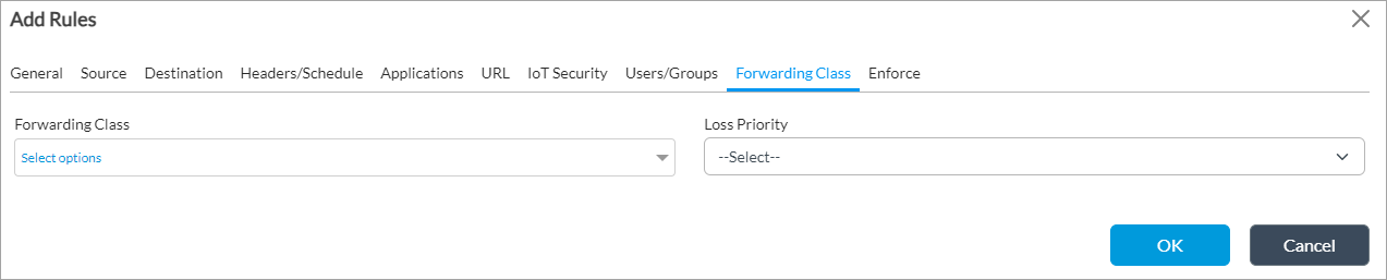
User Group Profile If you chose Selected in the Match Users field, select a user group profile to match users in a group. Local Database If you chose Selected in the Match Users field, click to create a local database to match users and user groups. Select these users and user groups in the Users and Groups tables. External Database If you chose Selected in the Match Users field, click to use an external database to match users and user groups. Select these users in the Users table. Users If you chose Selected in the Match Users field, click the Add icon and select a user. Select + New Custom User to add a user.Groups If you chose Selected in the Match Users field, click the Add icon and select a user group. Select + New Custom Group to add a user group. - Select the Forwarding Class tab to choose the forwarding classes and loss priorities to match. Enter information for the following fields.
Note that in some situations, such as App QoS policy, a forwarding class may not be assigned to a session until the second packet in the session or sometimes until the eighth packet in the session. For this reason, it is recommended that you do not configure a match based on the forwarding class for sessions that consist only of a few packets. Also, do not configure anything on the Forwarding Class tab if you are also configuring DIA or next-hop selection rules in the SD-WAN forwarding profile.

Field Description Forwarding Class Select the forwarding class to match:
- Forwarding Class 0 (network control)
- Forwarding Class 1
- Forwarding Class 2
- Forwarding Class 3
- Forwarding Class 4 (expedited forwarding)
- Forwarding Class 5
- Forwarding Class 6
- Forwarding Class 7
- Forwarding Class 8 (assured forwarding)
- Forwarding Class 9
- Forwarding Class 10
- Forwarding Class 11
- Forwarding Class 12 (best effort)
- Forwarding Class 13
- Forwarding Class 14
- Forwarding Class 15
Loss Priority Select the loss priority to assign to the forwarding class:
- High—Traffic has a greater likelihood of being dropped.
- Low—Traffic has a lesser likelihood of being dropped.
- Select the Enforce tab to select the actions to take on matching packets, including applying a forwarding and a logging profile. Enter information for the following fields.

Field Description Forwarding (Group of Fields) - Action (Required)
Select the action to take on matching traffic: - Allow Flow
- Deny Flow
- Forwarding Profile
Select the forwarding profile to apply to matching traffic. - View Forwarding Profile
Click to view the selected forwarding profile. Logging (Group of Fields) Log changes in the forwarding action. - LEF Profile
Select a LEF profile. Logs are sent to the active collector of the LEF profile. For information about configuring a LEF profile, see Configure Log Export Functionality. For information about associating a LEF profile with a feature or service, see Apply Log Export Functionality. - Default Profile
Click to use the default LEF profile instead of the profile from the LEF profile field. For information about configuring a default LEF profile, see Configure Log Export Functionality. - Event
Select the events to log: - All SLA Violated—Generate a log when the session moves to or from an SLA-violated circuit.
- Priority Change—Generate a log when the session moves between circuits of different priorities.
- Never—Never log changes.
Default: Never
- Rate Limit
Enter the number of logs to generate per second. You should configure a rate limit when changes happen constantly, to buffer all changes logged during the specified interval and send them together in a single message.
Range: 10 to 200
Default: 10
- Click OK.
Configure Policy Rules for Layer 3 SD-WAN Policy
In policy rules, you configure the conditions for matching packets of interest, and you also configure the forwarding, logging, and monitoring actions to take on the packets that match the conditions. To configure policy rules, you select an organization (that is, a tenant), and then you select one of the tenant's post-staging templates. Then you perform the following steps, which are described in the procedure below:
- Add a new rule (Steps 1 through 5).
- Configure a rule name (Step 6).
- Configure match conditions:
- Configure address, site, and zone match criteria (Steps 7 through 18).
- Configure match criteria based on the contents of the IP packet header and to set a time at which to apply the policy (Step 19).
- Configure application and SaaS application match criteria (Steps 20 through 27).
- Configure match criteria for URL categories (Steps 28 through 30).
- Define the users and user groups to which the rule applies (Step 31).
- Select the forwarding classes and loss priorities to match (Step 32).
- Select the actions to take on matching packets, including applying a forwarding and a logging profile and defining monitor parameters (Step 33).
When you configure the match conditions for a policy rule, you configure each group of related rules on a single tab on the Add Rules popup window. All rule values that you configure on the same tab, and within the same pane on a tab, are processed as a logical OR function, and rule values that you configure on different tabs are processed as a logical AND function. For example, if you include multiple addresses in the source address field, any one of the addresses can fulfill the match criteria for that field. If you include multiple source addresses and if you also configure a source zone (on the same tab, but in different panes), the traffic must match one of the source addresses AND one of the source zone parameters.
To configure a policy rule:
- In Director view:
- Select the Configuration tab in the top menu bar.
- Select Templates > Device Templates in the horizontal menu bar.
- Select an organization in the left navigation bar.
- Select a post-staging template in the main panel. The view changes to Appliance view.
- Or, to configure a policy rule for a device's policy, select Devices > Devices in Step 1b and then select a device in the main pane.
- Select the Configuration tab in the top menu bar.
- Select Services > SD-WAN > Policies in the left menu bar. In the main pane, the Rules tab in the horizontal menu bar is selected, and the table displays a list of configured rules. To display more of the rule components, scroll the main pane horizontally.

- Click the Add icon to add a rule. The Add Rules window displays.
- (For Releases 21.2.1 and later.) If you already added one or more rules, the Add Rule popup window displays the rule reorder window. Select where you want to insert the rule, either at the end of the existing rules, the top of the existing rules, or in a specific location in the list of existing rules.

- Click Continue.
- The Add Rule popup window displays.

- Select the General tab, and enter a name for the rule and a text description for the rule.
- Select the Source tab to configure match criteria based on source addresses, source MAC addresses, source zone, source site names. These match criteria match traffic coming from ptvi (overlay) interfaces from the configured remote sites or zones.

- Click the Add icon in the Source Zone pane, For zones that you have configured for interfaces and networks, select the source zone to apply the rule to traffic coming from any interfaces or networks in the zone. Note that you cannot configure source zones for zones that you have configured for routing instances or for organizations. For information about configuring zones, see Configure Zones and Zone Protection Profiles.
- Click + New Zone to add a zone. In the Add Zone popup window, enter information for the following fields.

Field Description Name (Required) Enter a name for the zone. Description Enter a text description for the zone. Tags Enter a keyword or phrase that allows you to filter the zone. This is useful when you have many zones and want to view those that are tagged with a particular keyword. Zone Protection Profile Select a zone protection profile. + Create Zone Protection Profile Click to create a zone protection profile. Log Profile Select a log profile. + Create Log Profile Click to create a log profile. Interface and Network Click to specify the interfaces and networks that are in the zone. In the Interfaces and Networks panes, select the interfaces and network that are in the zone. Click the Add icon to add interfaces or networks.OK Click OK. - Click the Add icon in the Destination one pane. For zones that you have configured for interfaces and networks, select the destination zone to apply the rule to traffic going to any interfaces or networks in the zone. Note that you cannot configure destination zones for zones that you have configured for routing instances or for organizations. For information about configuring zones, see Configure Zones and Zone Protection Profiles. Click + New Zone to add a zone, as described in Step 9.
- In Source Site Name pane, select the source sites to match. Click the Add icon to add source sites.
- In Destination Name Site pane, select the destination site to match. Click the Add icon to add destination sites.
- Click the Add icon in the Source Address pane, and from the drop-down list select the source address, source address group, or source address region of incoming traffic to match.
-
Click + New Address to add a source address. In the Add Address popup window, enter information for the following fields.

Field Description Name Enter a name for the source address. Description Enter a text description for the source address. Tags Enter a keyword or phrase that allows you to filter the source address. This is useful when you have many addresses and want to view those that are tagged with a particular keyword. Type and Address/Prefix
(Required)Select the type of IP address to match and the value to match. The name of the Address/Prefix field changes depending on the value you select in the Type field.
- IPv4 (type);
IPv4 Address/Prefix (match)
Evaluate the address match using an IP address within the IPv4 prefix specified in the IPv4 Address/Prefix field. This is the default. - IPv4 Wildcard Mask (type);
IPv4 Wildcard Mask (match)

(For Releases 20.2.2 and later.) Enter a wildcard mask for an IPv4 address. The bits in the mask can be on (1) or off (0). Only the bits that are enabled in the mask are used to determine whether an IPv4 address matches. When a bit in a wildcard mask is on, that bit must match. When a bit in a wildcard mask is off, it is considered as a "don't care" bit and is disregarded for purposes of address matching. For example, the IPv4 address and mask 192.168.3.100/255.255.3.255 matches any IPv4 address 192.168.x.100, where, for x, the first 6 bits can be on (1) or off (0) and the last two bits must be on (11). Note that in a wildcard mask, at least one bit must be on.
You can configure overlapping wildcard addresses.
A single session can match a maximum of 16 wildcard addresses.
You can configure wildcard address objects individually or as part of address groups.
You cannot combine an address prefix (or range) match with wildcard addresses to match a source or destination address.
- IPv4 Range (type);
IPv4 Range (range)

Evaluate the address match using an IP address within the IPv4 address range specified in the IPv4 Range field.
- IPv6 Address/Prefix (type);
IPv6 Address/Prefix (range)

Evaluate the address match using any of the IP addresses within the IPv6 address range specified in the IPv6 Address/Prefix field.
- FQDN (type);
FQDN (match)

Evaluate the address match using an IP address returned in a DNS query that resolves the fully qualified domain name (FQDN) into an IP address. The FQDN cannot contain any wildcard characters.
- Dynamic Address (type);
no range

(For Releases 22.1.3 and later.) Use a dynamic address object, which is a container for an IP address list that can change dynamically. Using dynamic addresses in a policy allows you to perform a configuration before the IP addresses are known, thus avoiding the need to update the configuration each time IP addresses are added or deleted. You typically configure dynamic address objects for hosts whose IP addresses may change later, for example, if you are performing a live migration of virtual machines (VMs) using the vSphere vMotion technology to migrate a VM from one cluster to another, which changes the IP address of the VM.
To configure a dynamic address object, issue the set orgs org-services tenant name objects addresses address object name dynamic-address CLI command.
To update the list of IP addresses associated with a dynamic address object without updating the configuration, issue the request orgs org-services tenant name objects dynamic-address add name tenant name address private-internet-IP address CLI command.
OK Click OK. - IPv4 (type);
- Click + New Address Group to add an address group. In the Add Address Group popup window, enter information for the following fields.

Field Description Name (Required) Enter a name for the address group. Description Enter a text description for the address group. Tags Enter a keyword or phrase that allows you to filter the address group. This is useful when you have many address groups and want to view those that are tagged with a particular keyword. Address Click the
 Add icon to select an address from the drop-down list to add to the group.
Type Select a group type:
- Dynamic
- Static
+ Address Click to add a new address to the group. In the Add Address popup window, enter a name, description, and tags for the address, select the IP address type (IPv4 or IPv6), and enter the IP address prefix. Address File Click the Add icon to select an address file from the drop-down list. The address file contains IP addresses to add to the group.+ Address File Click to upload a file containing IP addresses to the Versa Operating SystemTM (VOSTM) device. In the Upload Address Files to Appliance popup enter, select the filename in the Filename field. The Appliance field displays the name of the VOS device, which is the name of the tenant's device. OK Click OK. - Click Source Address Negate below the Source Address pane to block traffic to the selected source addresses instead of accepting it.
- Select a Routing Instance from the drop-down menu.
- Click the Add icon in the Destination Address pane, and from the drop-down list, select a destination address, destination address group, or destination address region of traffic that you want to match. You add new addresses or address groups to the Destination Address pane, and you can negate destination addresses, in the same way as for the Source Address pane, as described in Steps 14 through 16.
- Select the Headers/Schedule tab to configure match criteria based on the contents of the IP packet header and to set a time at which to apply the policy. Enter information for the following fields.

Field Description IP (Group of Fields) - IP Version
Select the IP version:
- IPv4
- IPv6
- IP Flags
Select whether routers can fragment data packets: - Don't Fragment
- More Fragments
- DSCP
Click the Add icon to a a differentiated services code point (DSCP) value.TTL (Group of Fields) - Condition
Select the TTL condition to use for the match. The TTL is the number of hops that a packet can travel before it is discarded and indicates the lifespan of a packet. The condition can be one of the following boolean values: - Equal to—TTL value must be equal to the specified value to trigger the security access rule
- Greater than or equal to—TTL value must be greater than or equal to the specified value to trigger the security access rule
- Less than or equal to—TTL value must be less than or equal to the specified value to trigger the security access rule
- Value
Enter the value for the TTL. Others (Group of Fields) - Schedules
Select a schedule to set the time and frequency at which the rule is in effect.
- + Schedule
Click to create a schedule. In the Create Schedule popup window, enter information for the following fields.

- Name (Required)—Enter a name for the schedule.
- Description—Enter a description for the schedule.
- Tags—Enter a keyword or phrase that allows you to filter the schedule name.
- Recurrence—Select Non-Recurring (for a one-time schedule), Daily, or Weekly.
- State Date, Start Time, End Date, and End Time—Enter or select the starting and ending date and time for the schedule. Then click the
 Add icon.
Then, click OK.
Services (Group of Fields) - Service List
Select the services to allow or block. Click the Add icon to select a service from the drop-down list. The list includes predefined and user-defined services. A service is defined based on the destination address and port.- + New Service
Click to create a service. In the Add Service popup window, enter information for the following fields.

- Name (Required)—Enter a name for the service.
- Description—Enter a description for the service.
- Tags—Enter a keyword or phrase that allows you to filter the service name.
- Protocol—Click and enter a protocol name in the second Protocol field.
- Protocol Value (Required)—Click and enter a protocol number in the second Protocol Value field.
- Port—Click and in the second Port field, enter a source or destination port number.
- Source/Destination—Click and enter a port number in the Source Port and Destination Port fields.
Then, click OK.
- Select the Applications tab to configure matching criteria for applications and SaaS application groups.

- In the Applications table, click the Add icon and select an application list from the drop-down list, which includes predefined and user-defined applications. For more information about predefined and user-defined applications, see Configure NGFW.
- To add an application group, click + New Group. In the New Group popup window, enter a name for the group, a description, and tags, and select or add applications to the group. Click OK.

- To add an application filter, Click + New Filter. In the New Filter popup window, enter a name for the filter, select the desired filters, and click OK.

- To add an application, click + New Application. In the New Application popup window, enter information for the following fields.

Field Description Name (Required) Enter a name for the application. Description (Required) Enter a description for the application. Precedence (Required) Enter a value for the priority of the application. Application Timeout Enter how long to wait before timing out the application, in seconds.
Range: 1 through 86400 secondsApp Match IPs Click to match the IP address of the application. - In the Attributes tab, enter information for the following fields.
Field Description Family
Select the family to which the application belongs. Subfamily
Select the subfamily to which the application belongs. Risk
Select the risk level to assign to the application. A value of 1 indicates the lowest risk level, and a value of 5 indicates the highest. Productivity
Select a productivity level to assign to the application. Application Tags
Select one or more security, SD-WAN and general tags to associate with the application. - Select the Match Information tab. In the Add Match Information popup window, enter information for the following fields.

Field Description Name (Required) Enter a name for the application match. Host Pattern Enter the host pattern to match. Protocol Value Enter the application's protocol name or number. Source Address Enter the source address of the application. Destination Address Enter the destination address of the application. Source Port (Group of Fields) Click to match the source ports of the application. - Value or Range
Click to match a single source port of the application. - Range
Click to match a range of source ports of the application. - Source Port Value
Enter the source port number. - Low
For a range of source ports, enter the lowest port number. - High
For a range of source ports, enter the highest port number. Destination Port (Group of Fields) Click to match destination ports of the application. - Value
Click to match a single destination port of the application. - Range
Click to match a range of destination ports of the application. - Destination Port Value
Enter the destination port number. - Low
For a range of destination ports, enter the lowest port number. - High
For a range of destination ports, enter the highest port number. - Click OK.
- Select the URL tab to configure match criteria for URL categories. Note that for URL matching to work, you must enable the URL category cache. For more information, see Configure Application and URL Category Detection Parameters, below.

- In URL Category List, click the Add icon and select a URL category from the drop-down list.
- To add a URL category, click + New URL Category. In the New URL Category popup window, enter information for the following fields. For more information, see Configure URL Filtering.

Field Description Name (Required) Enter a name for the URL category. Description Enter a description for the URL category. Tags Enter a keyword or phrase that allows you to filter the URL category. This is useful when you have many categories and want to view categories that are tagged with a particular keyword. Confidence Enter a confidence value for the URL category. The confidence value is used to break a tie when multiple URL categories match a single URL. If a URL matches multiple categories, the one with the higher confidence value takes precedence.
Range: 1 through 100
URL File Select a file that contains URL patterns or strings. URL Patterns (Tab) - Pattern
Enter a URL pattern to match a group of URLs. The pattern can include regex patterns. For example, you can enter www.versa-networks.com or *.versa-networks. If you include a backslash (\) in the regex pattern, you must escape it by preceding it with a backslash.
- Reputation
Select a reputation to assign to the URL pattern. The following are the predefined URL reputation types, listed in order from lowest to highest risk:
- Trustworthy
- Low Risk
- Moderate Risk
- Suspicious
- High
- Add icon
Click to add the URL pattern to the URL category. URL Strings (Tab) - String
Enter a URL string to match a single URL. - Reputation
Select a reputation to assign to the URL string. The following are the predefined URL reputation types, listed in order from lowest to highest risk:
- Trustworthy
- Low Risk
- Moderate Risk
- Suspicious
- High
- Add icon
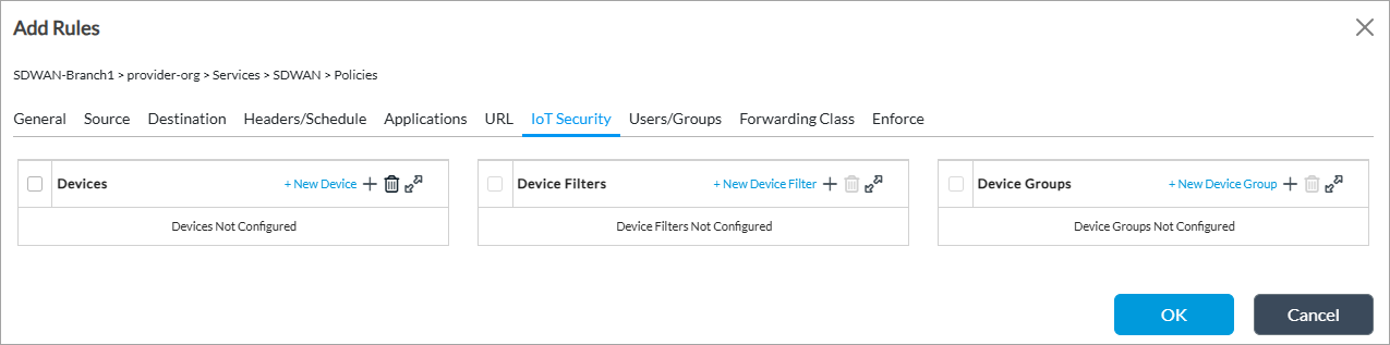
Click to add the URL string to the URL category. - To configure Internet of Things (IoT) security devices, IoT device filters, and IoT device groups, select the IoT Security tab. For more information, see Configure IoT Security.
- Select the Users/Groups tab to define the users and user groups to which the rule applies. Enter information for the following fields.

Field Description Match Users Select the users to match:
- Any—If you select to match any users, you cannot configure any other fields on this tab.
- Known—If you select to match known users, you cannot configure any other fields on this tab.
- Selected—If you select to match selected users, you can configure the other fields on this tab.
- Unknown—If you select to match unknown users, you cannot configure any other fields on this tab.
User Group Profile If you match selected users, select a user group profile to match users in a group. Local Database If you match selected users, click to create a local database to match users and user groups. Select these users and user groups in the Users and Groups fields. External Database If you match selected users, click to use an external database to match users and user groups. Select these users in the Users and Groups fields. Users If you match selected users, click the Add icon and select a user from the drop-down list. Select + New Custom User to add a user.Groups If you match selected users, click the Add icon and select a user group from the drop-down list. Select + New Custom Group to add a user group. - Select the Forwarding Class tab to choose the forwarding classes and loss priorities to match. Enter information for the following fields.
Note that in some situations, such as App QoS policy, a forwarding class may not be assigned to a session until the second packet in the session or sometimes until the eighth packet in the session. For this reason, it is recommended that you do not configure a match based on the forwarding class for sessions that consist only of a few packets. Also, do not configure anything on the Forwarding Class tab if you are also configuring DIA or next-hop selection rules in the SD-WAN forwarding profile.
Field Description Forwarding Class Select the forwarding class to match:
- Forwarding Class 0 (network control)
- Forwarding Class 1
- Forwarding Class 2
- Forwarding Class 3
- Forwarding Class 4 (expedited forwarding)
- Forwarding Class 5
- Forwarding Class 6
- Forwarding Class 7
- Forwarding Class 8 (assured forwarding)
- Forwarding Class 9
- Forwarding Class 10
- Forwarding Class 11
- Forwarding Class 12 (best effort)
- Forwarding Class 13
- Forwarding Class 14
- Forwarding Class 15
Loss Priority Select the loss priority to assign to the forwarding class:
- High—Traffic has a greater likelihood of being dropped.
- Low—Traffic has a lesser likelihood of being dropped.
- Select the Enforce tab to select the actions to take on matching packets, including applying a forwarding and a logging profile and defining monitor parameters. Enter information for the following fields.
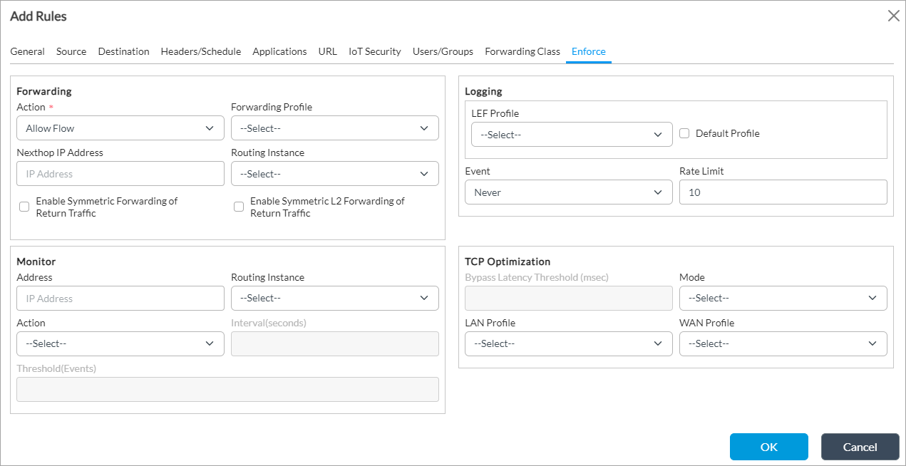
Field Description Forwarding (Group of Fields) - Action (Required)
Select the action to take on matching traffic: - Allow Flow
- Deny Flow
- Forwarding Profile
Select the forwarding profile to apply to matching traffic. - Next-Hop IP Address
Enter the IP address of the next hop to which to forward the flow. Using a next hop statically assigns the next hop instead of using dynamic routing. - Routing Instance
Select the routing instance to reach the next hop. - Enable Symmetric Forwarding of Return Traffic
Click to enable symmetric forwarding of return traffic. With this option, after a route lookup is performed, the reverse traffic flow transits through the same interface on which the flow was received. To effect symmetric forwarding, the VOS software records the (tunnel) interface on which the forward-direction traffic for the session arrives and places the reverse-direction traffic on that same tunnel interface. You do not need to install any static routes to make this happen. You can configure an SD-WAN or a policy-based forwarding (PBF) policy rule to subject the reverse direction traffic to a stateful Layer 3 return.
You should use this option to enforce symmetric traffic return only over a non-SD-WAN VPN tunnel (for example, a paired TVI tunnel, GRE tunnel, or IPsec tunnel). You should not use this option to enforce symmetric traffic return over SD-WAN VPN tunnels, that is, to send traffic back to the same branch, over the same SD-WAN path on which the forward direction traffic arrived. Instead, you should use the symmetric forwarding option in the SD-WAN forwarding profile.
The following are a few examples of when symmetric forwarding of return traffic might be useful:
- You want to do application-based DIA. You do this by creating the appropriate PDF or SD-WAN rule in the LAN VR to send forward-direction traffic for the application session (say S1) over a paired TVI/split tunnel into the transport VR. Here, a second session, S2, is created and traffic is source-NATed before it is transmitted on the WAN interface. One way for the reverse-direction traffic of session S2 to get back to the LAN VR is to use routing (VOS Workflows set up BGP between the LAN and and transport VR, or you can use static routes). This works fine except if you have multiple LAN VRs with overlapping address spaces. In this case, you can create a second PBF rule to match the traffic coming into the transport VR over the WAN side of the split tunnel (for example, “match source zone w-st-lan-internet") and statefully send reverse-direction traffic for S2 back over the tunnel without requiring a route.
- You want to selectively divert some internet-bound traffic to a cloud security device, such as a Zscaler, over an IPsec or a GRE tunnel. You may pace this tunnel in a different routing instance (such as a Zscaler VR) and send traffic to it over a split tunnel to that routing instance, from where it can reach the Zscaler VR over the IPsec or GRE tunnel. Again, the reverse-direction traffic (traffic coming back from the Zscaler VR) either needs a route to get to the LAN or you can configure a PBF rule that includes the enforce symmetric forwarding option.
- Enable Symmetric Layer 2 Forwarding of Return Traffic
Click to enable symmetric Layer 2 forwarding of return traffic. With this option, no route lookup is performed, and the reverse traffic flow transits through the same interface on which the flow was received and is sent to the same MAC address from which the traffic was received. You can configure an SD-WAN or a PBF policy rule to subject the reverse direction traffic to a stateful Layer 2 return.
Click to enable stateful layer 2 forwarding of reverse-direction traffic to the same MAC address from which the forward-direction traffic is received. This is an advanced configuration for SD-WAN or PBF policy rules and is applicable to a very specific use case; you must not enable it in any other use case. Specifically, you enable it when forward-direction traffic is sourced from a Layer 2 adjacent service function, such as a WAN optimization device, that spoofs the client IP address. Normally, for such traffic, the reverse-direction traffic must also be diverted back to the same function. However, regular routing-based forwarding prevents this from happening: the traffic is forwarded wherever the route lookup points to. To enable route-less forwarding of reverse-direction traffic to the same function, you create an SD-WAN or PBF rule that matches the forward-direction traffic and for which you select the Enable Symmetric Layer 2 Forwarding of Return Traffic option.
Logging (Group of Fields) Log changes in the forwarding action. - LEF Profile
Select a LEF profile. Logs are sent to the active collector of the LEF profile. For information about configuring a LEF profile, see Configure Log Export Functionality. For information about associating a LEF profile with a feature or service, see Apply Log Export Functionality. - Default Profile
Click to use the default LEF profile instead of the LEF profile from the previous field. For information about configuring a default LEF profile, see Configure Log Export Functionality. - Event
Select the events to log: - All SLA Violated—Generate a log when the session moves to or from an SLA-violated circuit.
- Never—Never log changes. This is the default.
- Priority Change—Generate a log when the session moves between circuits of different priorities.
Default: Never
- Rate Limit
Enter the number of logs to generate per second. You should configure a rate limit when changes happen constantly, to buffer all changes logged during the specified interval and send them together in a single message.
Monitor (Group of Fields) Enter Monitor information when you specify a next-hop IP address in the forwarding Action. In the fields in this section, specify the parameters to monitor and the actions to take if the monitoring fails. - Address
Enter the IP address to monitor using ICMP probes. - Action
Select the monitoring action to take: - Failover—Route traffic and do not implement the SD-WAN traffic policy. A route lookup is performed to determine the Layer 3 destination IP address.
- Next-Rule—Evaluate the other rules until a match is found. If no match is found, route the traffic.
- Wait-Recover—Drop traffic until the next hop recovers.
- Threshold (Events)
Enter the number of successive ICMP ping failures after which the next hop is considered down. - Routing Instance
Select the routing instance to use or the VRF in which you want to run the monitor. - Interval
Enter how often to send ICMP probes, in seconds. TCP Optimization (Group of Fields) - Bypass Latency Threshold
Enter how much latency must be measured before TCP optimizations begin.
Range: 0 through 60000 milliseconds
Default: 10 milliseconds
- Mode
Select a TCP optimization mode:
- Auto
- Bypass—Disable TCP optimizations.
- Forward proxy
- Proxy
- Reverse proxy
- Splice
- LAN Profile
Select a LAN profile.
If you select proxy mode, you must configure a TCP profile.
If you do not select a TCP profile, a system default LAN profile is applied that uses the cubic congestion control algorithm and duplicate ACK loss detection.
- WAN Profile
Select a WAN profile.
If you select proxy mode, you must configure a TCP profile.
If you do not select a TCP profile, a system default WAN profile is applied that uses the BBR congestion control algorithm and RACK loss detection.
- Click OK.
Configure Application and URL Category Detection Parameters
For Layer 3 SD-WAN policy, application and URL-category detection allow an SD-WAN traffic-steering policy to correctly process all traffic in a flow. These two detection systems are always running on a VOS device.
Application and URL-category detection inspect the Layer 7 (application) payload. However, most applications other than basic ones such as ICMP and DNS are identified only after a few packets for the session have been received. Because SD-WAN policies are often used to override route table–based routing and divert the traffic to a different path, the application must be identified correctly on the first packet instead of after a few packets so that the SD-WAN policy is applied to all packets in the flow. The rapid identification is made possible by having application and URL category caches, which are used to identify the application in the first packet, instead of waiting for the application identification engine to do so.
By default, application caching is enabled.
To configure application and URL detection parameters:
- In Director view:
- Select the Configuration tab in the top menu bar.
- Select Templates > Device Templates in the horizontal menu bar.
- Select an organization in the left menu bar.
- Select a template in the main pane. The view changes to Appliance view.
- Select the Configuration tab in the top menu bar.
- Select Services > SD-WAN > Application Detection in the left menu bar. The main pane displays the Application Detection and Application Steering panes.

- Click the
 Edit icon in the Application Detection pane and enter information for the following fields.

Field Description Application Dynamic Detection Click the checkbox to dynamically re-evaluate SD-WAN traffic-steering rules when an application or URL category is detected in a traffic flow even if the packet being inspected is not the first packet in the flow.
Default: DisabledApplication Cache Click the checkbox to cache applications associated with server IP address and port numbers.
Default: DisabledURL Category Cache Click the checkbox to cache URL categories associated with HTTP and HTTPS server IP addresses and port numbers.
Default: Disabled - Click Save.
- Click the Edit icon in the Application Steering pane. In the Edit Application Steering popup window, enter information for the following fields.

Field Description Session Pinning (Group of Fields) Configure path affinity.
- Domain Application Cache
Click to pin subsequent sessions of an SaaS application transaction to the path used by the DNS query. - Client Route Cache
Click to pin all consecutive sessions of a SaaS application transaction between a specific client and server to the same path. Timeout (Group of Fields) Configure the timeout period for session pinning. - Application Metrics
Enter the maximum time, in seconds, that a link with the worst metric has to wait before trying again.
Default: 300 seconds
- Client Route Cache
Enter the maximum time, in seconds, that sessions between a host and client remain pinned to the same link.
Default: 30 seconds - Click Save.
Verify the SD-WAN Policy Configuration
To verify the SD-WAN policy configuration:
- In Director view, select the Monitor tab in the top menu bar.
- Select the organization in the left navigation panel.
- Select the Devices tab in the horizontal menu bar.

- Select a device in the main pane. The view changes to Appliance view.

- To view the Layer 2 SD-WAN policy configuration:
- In the Services tab, select SD-LAN.
- Select the Policies tab.
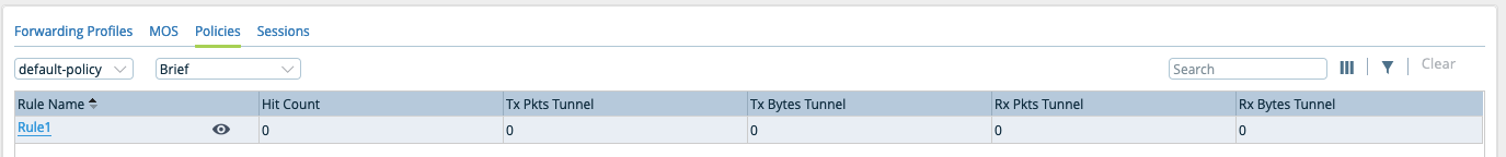
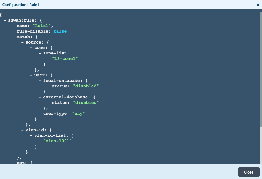
- Click the policy name to view the policy configuration.
- To view the Layer 3 SD-WAN policy configuration:
- In the Services tab, select SD-WAN.
- Select the the Policies tab.
- Click the policy name to view the policy configuration.
Supported Software Information
Releases 20.2 and later support all content described in this article, except:
- Release 21.2.1 adds support for configuring Layer 2 SD-WAN policy and for configuring rule order and matching based on the destination zone.
- Release 22.1.3 adds support for configuring a dynamic source address object.
Additional Information
Apply Log Export Functionality
Configure Address Objects
Configure CoS
Configure Layer 2 Services
Configure Log Export Functionality
Configure MOS Score Monitoring
Configure NGFW
Configure Policy-Based Forwarding
Configure SD-WAN Traffic Steering
Configure SLA Profiles for SD-WAN Traffic Steering
Configure URL Filtering
Configure User and Group Policy