Configure SD-WAN Path Policy
![]() For supported software information, click here.
For supported software information, click here.
When you use data-driven SLA monitoring, you configure SD-WAN path policies to direct traffic to the direct and alternate paths used to reach a destination.
Note that you can use SLA monitoring only to control SLA probes. You cannot apply firewall or QoS rules to SLA traffic egressing from the VOS device.
You can configure bandwidth monitoring using microtests, which initiate bandwidth testing more frequently than normal bandwidth tests. Note that when initiating microtests, the system does not run speedtests (upload/download tests) in active mode. Only a few TCP handshake packets are exchanged between the branch and hub nodes to share the live traffic bytes (Rx/Tx) on that particular access circuit.
To configure a path policy:
- In Director view:
- Select the Configuration tab in the top menu bar.
- Select Templates > Device Templates in the left menu bar.
- Select an organization in the left menu bar.
- Select a post-staging template in the main pane. The view changes to Appliance view.
- Select the Configuration tab in the top menu bar.
- Select Services > SD-WAN > Path Policies. The main pane displays a list of the path policies that are already configured.
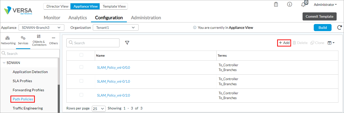
- Click the
 Add icon. The Add Path Policy popup window displays.
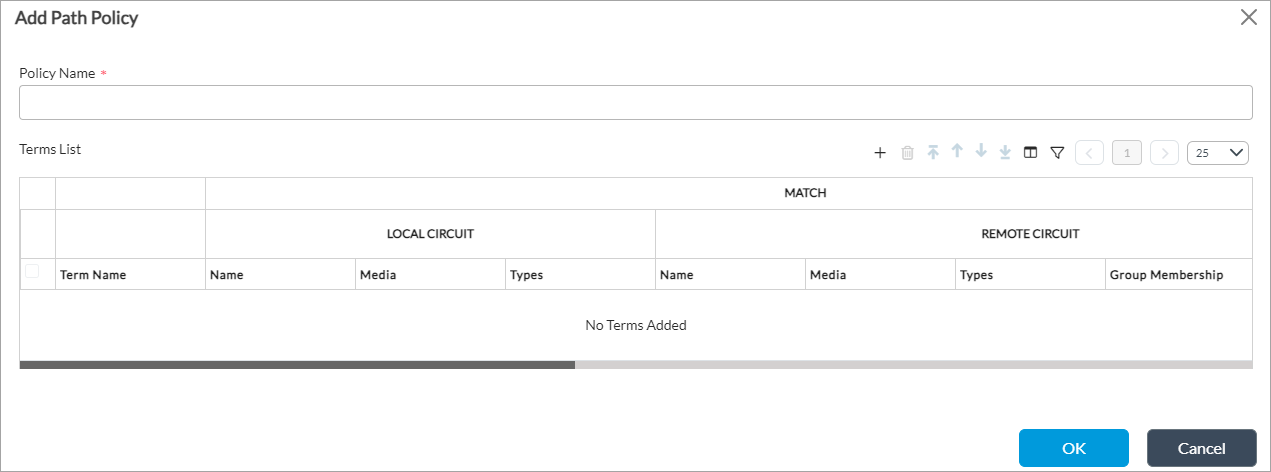
- In the Policy Name field, enter a name for the path policy.
- Click the Add icon to add a term for the path policy. The Add Terms popup window displays.

- In the Term Name field, enter a name for the path policy term.
- Select the Match tab to define policy match conditions. Enter information for the following fields.
Field Description Remote Site Type Select the type of the remote site:
- Branch
- Controller
Group Membership Click the Add icon and select the name of the remote hub group that you created when you configure a hub device.Circuit Names (Tab) Configure the WAN circuits to match, by circuit name. - Local
Click the Add icon. From the drop-down, select a WAN circuit name on the local branch. Circuits typically have names such as WAN1 and WAN2.- Remote
Click the Add icon. From the drop-down, select a WAN circuit name on the remote branch.Circuit Types (Tab) Configure the circuits to match, by circuit type. - Local
Click the Add icon. From the drop-down, select a WAN circuit type on the local branch. Circuits typically have types such as broadband, IP, and MPLS- Remote
Click the Add icon. From the drop-down, select a WAN circuit type on the remote branch.Circuit Media (Tab) Configure the circuits to match, by circuit media. - Local
Click the Add icon. From the drop-down, select a WAN circuit media on the local branch. Circuits typically have media such as cable, DSL, Ethernet, LTE, T1, and T3.- Remote
Click the Add icon. From the drop-down, select a WAN circuit type on the remote branch. - Select the Action tab to define the action to take if the match conditions are met. Enter information for the following fields.

Field Description SLA Monitoring (Group of Fields) Configure values to change the default SLA-monitoring parameters. - Interval
Enter how often to send SLA probes on each path between the branch nodes.
Range: 100 to 300000 milliseconds
Default: 10000 milliseconds- Logging Interval
Enter how often to log SLA measurements for each path to the Analytics node
Default: 300 seconds- Loss Threshold
Enter the number of consecutive SLA probes that must be lost for a path to be declared inactive.
Default: 3Adaptive SLA Monitoring (Group of Fields)
Click to enable adaptive SLA monitoring. - Inactivity Interval (Required)
Enter how long the path to a neighbor is inactive before VOS device switches the path to the suspended state. In this state the VOS device stops sending SLA monitor packets to the neighbor.
Range: 1 through 9000 seconds
Default: 300 seconds
- Suspend Interval (Required)
Enter how long the path remains in the suspended state. After this time expires, the VOS device resumes sending SLA monitor packets on the path to the neighbor.
Range: 1 through 9000 seconds
Default: 30 seconds
- Data Driven
Click to enable data-driven SLA monitoring. For more information, see Configure Data-Driven SLA Monitoring. Forwarding Class (Group of Fields)
Select the forwarding class or classes that the SLA monitoring configuration applies to. - FC General Configuration
Click the Add icon and select one or more predefined forwarding classes.- FC Specific Configuration
Click the Add icon to define a specific forwarding class configuration. To create a forwarding class, see Step 10.Bandwidth Monitoring (Group of Fields) Click to monitor the link bandwidth on a circuit. You can view the circuit bandwidth on the Monitor > Summary screen. To configure automatic path bandwidth measurement, see Configure Automatic Bandwidth Monitoring. - Interval
Enter how often to monitor the link bandwidth.
Range: 10 through 300 minutes
Default: 10 minutes
- Microtest Interval
(Release 23.1.1 and later.) Enter how often to monitor the link bandwidth using microtests, in seconds.
Range: 2 through 3600 seconds
Default: 10 seconds
- Microtest Status
Click to enable microtest, which is disabled by default. - To add a forwarding class configuration, click the Add icon in the FC Specific Config field. Enter information for the following fields.

Field Description Forwarding Class (Required) Select the forwarding class that the SLA monitoring configuration applies to. SLA Monitoring (Group of Fields) Configure values to change the default SLA-monitoring parameters. - Interval
Enter how often to send SLA probes on each path between the branch nodes.
Range: 100 to 300000 milliseconds
Default: 10000 milliseconds- Logging Interval
Enter how often to log SLA measurements for each path to the Analytics node
Default: 300 seconds- Loss Threshold
Enter the number of consecutive SLA probes that must be lost for a path to be declared inactive.
Default: 3- Alarm Soak Time
(For Releases 22.1.1 and later.) Enter a soak time, in seconds, to damp the sending of repetitive notifications.
Default: 0
Adaptive SLA Monitoring (Group of Fields) Click to enable adaptive SLA monitoring. - Inactive Interval (Required)
Enter how long a neighbor is inactive before VOS device switches the path to the suspended state. In this state the VOS device stops sending SLA monitor packets to the neighbor.
Range: 1 through 9000 seconds
Default: 300 seconds
- Suspend Interval (Required)
Enter how long the path remains in the suspended state. After this time expires, the VOS device resumes sending SLA monitor packets to the neighbor.
Range: 1 through 9000 seconds
Default: 30 seconds
- Click OK.
- Click OK in the Edit Path Policy popup window.
Supported Software Information
Releases 20.2 and later support all content described in this article, except:
- Release 22.1.1 adds support for alarm soak time for SLA monitoring.
- Release 23.1.1 supports the Microtest Interval and Microtest Status bandwidth-monitoring options when configuring an SD-WAN path policy.