Configure Reusable Objects
![]() For supported software information, click here.
For supported software information, click here.
You use the Configure lifecycle to create all configuration objects for secure SD-WAN deployments. This article describes the reusable objects that you can configure once and then reuse and reference multiple times in secure SD-WAN policy rules and profile configuration.
The following figure illustrates the reusable folder structures in the Configure lifecycle. To access the Configure lifecycle screen, select Configure in the left menu bar on the Concerto tenant's home screen. Then select Secure SD-WAN > Reusable Objects.

For each reusable object, you can perform the following actions, depending on the actions available. Click the ![]() Ellipses icon to display more actions available.
Ellipses icon to display more actions available.

- Filter (
 )—For Address Objects and Address Groups reusable objects, click the Filter icon to filter any matching IP address or subnet in any address range. In the drop-down list, select IP Address and enter an IP address or IP subnet, and then click Apply.
 - Add (
 )—Click to configure a new reusable object.
 - Clone (
 )—Click to create a copy of the reusable object. After you make changes to the reusable object, save it with a unique name.
 - Delete (
 )—Click to delete the reusable object.
 - Refresh (
 )—Click to refresh the reusable objects list.
 - View References (
 )—Click to view all the appliances using this reusable object.
 - Copy to Subtenant (
 )—Copy a reusable object to a subtenant.
 - View Audit Log—Click to view an audit log for the reusable objects.
You can view all references to any configuration object from other levels of the configuration hierarchy. When you change the configuration of an object, you can then choose which versions of an object should be updated with the newer version. For more information about viewing references to objects, see View References to Objects in the Configuration Hierarchies. For more information about propagating changes to an object, see Propagate Object Configuration Changes.
Address Groups
You can group website addresses, address objects, and other address groups to form address groups. Grouping addresses allows you to collectively apply the same security policies and rules to multiple addresses that require the same security handling, instead of having to apply security policies to each address individually.
You can configure address groups using one of the following methods:
- When you configure a policy that references address groups, you can click + Add Address Group to create a new address group inline.
- Configure the address group from the main menu. Then, when you configure a policy that references address groups, you can select that address group.
To create an address group when you configure a policy, continue to Add an Address Group, below.
To configure an address group from the main menu:
- In Tenant view, select Configure > SD-WAN > Reusable Objects > Address Groups.
- If you have not yet configured an address group object, click Add Address Group.
- If you have configured one or more address group objects, the following screen displays. Click the
 icon.
icon.

- Continue to Add an Address Group, below.
Add an Address Group
Complete the following workflow to create an address group.
- In step 1, Addresses, enter information for the following fields.
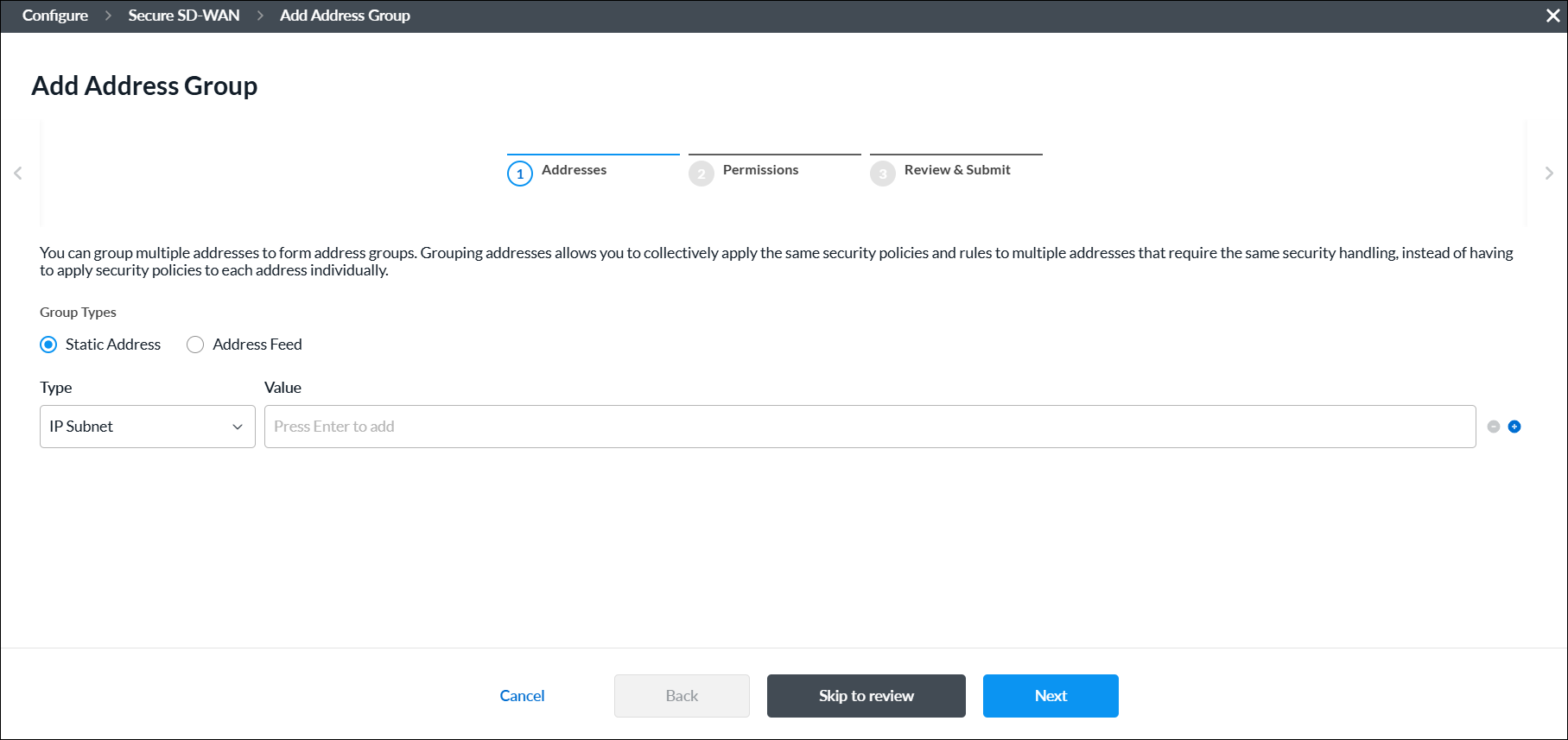
Field Description Group Types Select the IP address type for the group:
- Static IP Address
- Address Feed
Static Address
Select a static address group type:
- Address File
- Address Object
- Dynamic Address
- FQDN
- IP Range
- IP Subnet
- IP Wildcard
- IPv6 Subnet
Click the
 Add icon to add a new IP address group. You can add multiple Address Group types.
 Click the
 Minus icon to delete an IP address group.
- IP Addresses
Enter valid IP addresses for the type:
- IP Subnet—One or more IPv4 subnets, for example, 10.1.1.0/24
- IP Range—IP address range, for example, 10.2.1.1-10.2.2.2
- IP Wildcard—IP wildcard, for example, 192.168.0.56/255.255.0.255
- IPv6 Subnet—IPv6 subnet, for example, 2001:0db8:85a3:0000:0000:8a2e:0370:7334
- Address Files
When you select the Address Files type, select an address file.
To add a new address file:
- Click Add new file.

- In the Upload File screen, click Browse and select an address file to upload. The file must be in CSV format.

- Click Submit.
Address Feed
Enter one or more address feeds. - Click Next or select workflow step 2, Permissions.
- The permission for each role is selected by default, and you can update it. To change permissions for a role, select or deselect the Create, Read, Update, and Delete fields for the role.
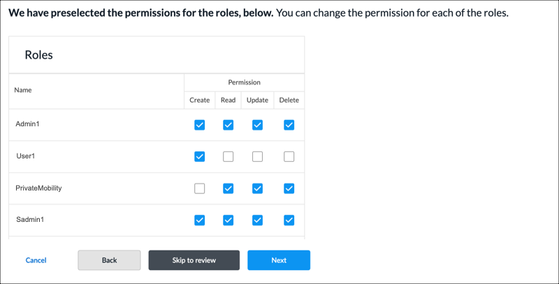
- Click Next or select workflow step 3, Review and Submit.
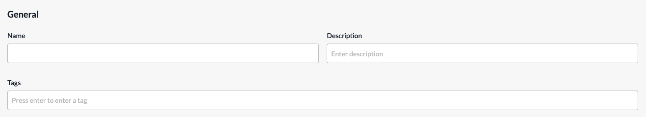
- In the General section, enter a name for the reusable object. You can also enter a description and tags. A tag is an alphanumeric descriptor, with no white spaces or special characters, that you can use to search the objects.
- For all other sections, review the information. Click the
 Edit icon to make changes, if needed.
 - Click Submit.
Address Objects
You can configure address objects using one of the following methods:
- When you configure a policy that references address objects, you can click + Add Address Objects to create a new address object inline.
- Configure the address object from the main menu. Then, when you configure a policy that references address objects, you can select that address object.
To create an address object when you configure a policy, continue to Add an Address Object, below.
To configure an address object from the main menu:
- In Tenant view, select Configure > SD-WAN > Reusable Objects > Address Objects.
- If you have not yet configured an address object, click Add Address Object.
- If you have configured one or more address objects, the following screen displays. Click + Add.

- Continue to Add an Address Object, below.
Add an Address Object
Complete the following workflow to create an address object.
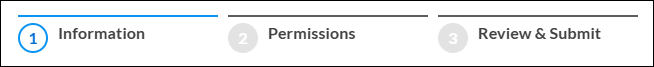
- In step 1, Information, enter information for the following fields.
Field Description Address Type Select an address type and enter the value of the address in the Address Value field. - IPv4 Subnet
Enter an IPv4 address to evaluate the address match using an IPv4 address. - IPv6 Subnet
Enter an IPv6 address to evaluate the address match using an IPv6 address. - IPv4 Range
Enter the IPv4 address range to evaluate the address match using an IPv4 address. - IPv4 Wildcard
Enter a wildcard mask for an IPv4 address. - IPv6 Wildcard
Enter a wildcard mask for an IPv6 address. - Dynamic Address
Use a dynamic address object, which is a container for an IP address list that can change dynamically. Using dynamic addresses in a policy allows you to perform a configuration before the IP addresses are known, thus avoiding the need to update the configuration each time IP addresses are added or deleted. - FQDN
Evaluate the address match using an IP address returned in a DNS query that resolves the FQDN into an IP address. - Click Next or select workflow step 2, Permissions.
- The permission for each role is selected by default, and you can update it. To change permissions for a role, select or deselect the Create, Read, Update, and Delete fields for the role.
- Click Next or select workflow step 3, Review and Submit.
- In the General section, enter a name for the reusable object. You can also enter a description and tags. A tag is an alphanumeric descriptor, with no white spaces or special characters, that you can use to search the objects.
- For all other sections, review the information. Click the Edit icon to make changes, if needed.
- Click Submit.
Applications
You can configure user-defined applications to use in higher-level policies and subprofiles. You can also modify a predefined application. The modified version of the a predefined application is referred to as a user-modified predefined application.
You can configure a user-defined application using one of the following methods:
- When you configure a policy that references applications, you can click + Add Application to create a new application inline.
- Configure the application from the main menu. Then, when you configure a profile that references an application, you can select that application.
To create a user-defined application inline when you are configuring a profile, continue to Add a User-Defined Application, below.
To configure a user-defined application from the main menu:
- In Tenant view, select Configure > SD-WAN > Reusable Objects > Applications.
The User-Defined Applications tab is displayed by default.- If you have not yet configured a user-defined application, click Add User-Defined Application.
- If you have configured one or more user-defined applications, the following screen displays. Click + Add.

- Continue to Add a User-Defined Application, below.
Add a User-Defined Application
Complete the following workflow to create a user-defined application.

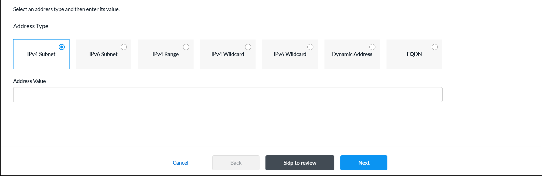
- In step 1, Application Identification, enter information for the following fields.
Field Description IP Prefix Enter a valid IP prefix and subnet. Note that if you select IP Prefix, you cannot also select Host Pattern. Host Pattern Enter a host pattern to detect. Note that if you select Host Pattern, you cannot also select IP Prefix. Protocol Select a protocol. If you selected Host Pattern, TCP is the only protocol available. Source Port If you select IP Prefix and either TCP or UDP, enter the source port number. You can enter a single port value or a range of values, for example, 500 and 1-100.
Range: 0 through 65535
Default: None
Destination Port If you select IP Prefix and either TCP or UDP, enter the destination port number. You can enter a single port value or a range of values, for example, 500 and 1-100.
Range: 0 through 65535
Default: None
+ Add Another Click + Add Another to add another match criteria. Application Precedence Enter a unique priority number to use when multiple applications match the traffic. The application with a higher precedence value is matched first.
Range: 0 through 65535
- Click Next or select workflow step 2, Application Attributes, and enter information for the following fields.

Field Description Risk Select a risk level. Each application has been assessed and assigned a risk level by the Versa Networks security research team, as follows:
- Level 1—Lowest Risk
- Level 2—Low Risk
- Level 3—Medium Risk
- Level 4—High Risk
- Level 5—Highest Risk
Productivity Select a productivity level. Each application has been assessed and assigned a productivity level by the Versa Networks security research team, as follows:
- Level 1—Lowest Productivity
- Level 2—Low Productivity
- Level 3—Medium Productivity
- Level 4—High Productivity
- Level 5—Highest Productivity
Application Tags—Security Select one or more security tags to associate with the application. Application Tags—SD-WAN Select one or more SD-WAN tags to associate with the application. Application Tags—General Select one or more general tags to associate with the application. Family Select a family to associate with the application. Subfamily Select a subfamily to associate with the application. - Click Next or select workflow step 3, Permissions.
- The permission for each role is selected by default, and you can update it. To change permissions for a role, select or deselect the Create, Read, Update, and Delete fields for the role.
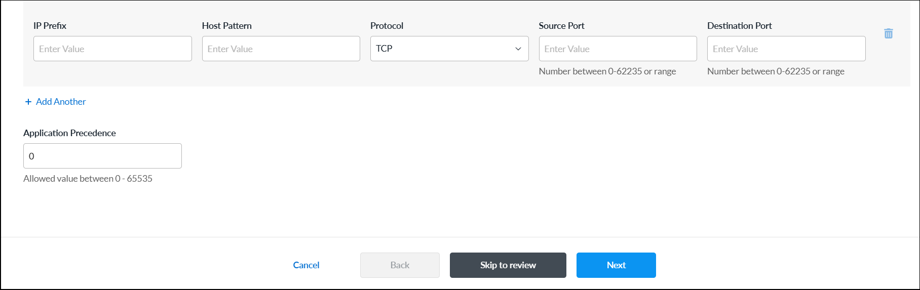
- Click Next or select workflow step 4, Review and Submit. In the General section, enter information for the following fields.
Field Description Name Enter a name for the user-defined application. Description Enter a description for the application. Tag Enter one or more tags to to associate with the application. A tag is an alphanumeric descriptor, with no white spaces or special characters, that you can use to search the objects. Upload Application Image Click the  Upload File icon. In the popup window, select an application image and upload it. Images must be in .png or .jpg format.
 - For all other sections, review the information. Click the Edit icon to make changes, if needed.
- Click Submit.
View and Modify Predefined Applications
- To view predefined applications, select the Predefined Applications tab.

- To modify a predefined application:
- Click the application name in the predefined applications list.

- In the Edit Predefined Applications screen, make the required changes, and then click Save.

- To view the user-modified predefined applications, select the User Modified Predefined Applications tab.
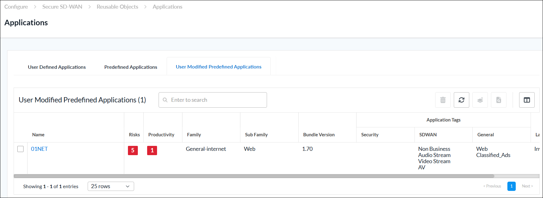
- Click the application name in the predefined applications list.
Application Groups
You can configure an application group using one of the following methods:
- When you configure a policy that references application groups, you can click + Add Application Group to create a new application group inline.
- Configure the application group from the main menu. Then, when you configure a policy that references an application group, you can select that application group.
To create an application group inline when you are configuring a profile, continue to Add a User-Defined Application Group, below.
To configure an application group from the main menu:
- In Tenant view, select Configure > SD-WAN > Reusable Objects > Application Groups.
The User-Defined Application Groups tab displays by default.- If you have not yet configured a user-defined application group, click Add User-Defined Application Group.
- If you have configured one or more user-defined application groups, the following screen displays. Click + Add.

- Continue to Add a User-Defined Application Group, below.
Add a User-Defined Application Group
Complete the following workflow to create an application group.

- In step 1, Applications, enter information for the following fields.
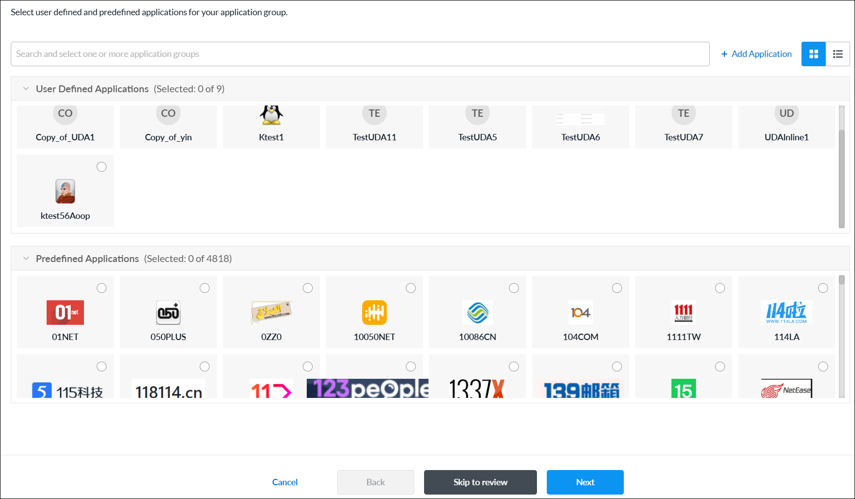
Field Description User-Defined Applications Select one or more user-defined applications to add them to the application group. Predefined Applications Select one or more predefined applications to add them to the application group. + Add Application Click to add a new user-defined application. See Add a User-Defined Application. - Click Next or select workflow step 2, Permissions.
- The permission for each role is selected by default, and you can update it. To change permissions for a role, select or deselect the Create, Read, Update, and Delete fields for the role.
- Click Next or select workflow step 3, Review and Submit.
- In the General section, enter information for the following fields.

Field Description Name (Required) Enter a name for the user-defined application group. Description Enter a description for the application group. Tag Enter one or more tags to to associate with the application group. A tag is an alphanumeric descriptor, with no white spaces or special characters, that you can use to search the objects. Upload Application Group Image Click the Upload File icon. In the popup window, select an application group image and upload it. Images must be in .png or .jpg format. - For all other sections, review the information. Click the Edit icon to make changes, if needed.
- Click Submit.
- To view predefined application groups, select the Predefined Application Groups tab.

Application Categories
Custom application categories are used to match information based on the attributes of the applications. For each category, you can create one or more filters:
- Application Risk—Each application has been assessed and assigned a risk level (1 through 5, lowest to highest) by the Versa Networks security research team.
- Application Productivity—Each application has been assessed and assigned a productivity level (1 through 5, lowest to highest) by the Versa Networks security research team.
- Application Tags—You can configure up to three types of application tags:
- Security
- SD-WAN
- General
- Application Family and Subfamily—You can select any of five application families and 34 application subfamilies.
You can use application categories when you configure application policies and rules, such as policies and rules for quality of service (QoS) and traffic steering.
You can configure application categories using one of the following methods:
- When you configure application policies and rules that references application categories, you can click + Create New to create new application categories inline.
- Configure the application categories from the main menu. Then, when you configure application policies and rules that references an application category, you can select that application category.
To add an application category inline when you are configuring application policies and rules, continue to Add Application Categories, below.
To configure an application category from the main menu:
- In Tenant view, select Configure > SD-WAN > Reusable Objects > Application Categories.
- If you have not yet configured an application category, click Add Application Category.
- If you have configured one or more application categories, the following screen displays. Click + Add to configure a new application category.

- Continue to Add Application Categories, below.
Add Application Categories
Complete the following workflow to create an application category.
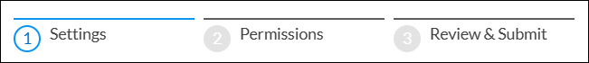
- In step 1, Settings, enter information for the following fields.
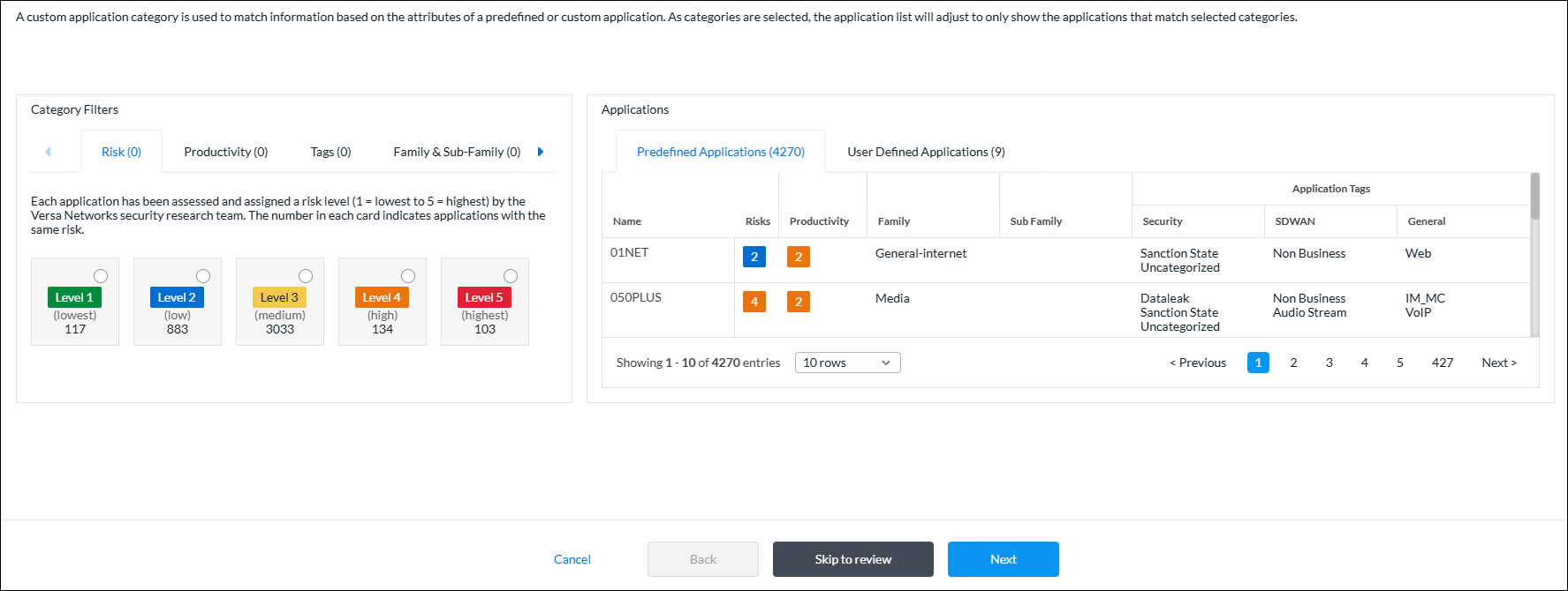
As you select categories, the application list adjusts to only show the applications that match selected categories. For example, in the sample screen above, 4,270 predefined applications and 9 user-defined applications are selected. Because no filters have yet been configured, these numbers represent the total number of predefined and user-defined applications that are available. The numbers change as you configure the various application filters. If you select multiple filters, the list changes to display the applications that match all of the filters you selected. - To customize the application risk filter, click the Risk tab in the Category Filters section, and then select one or more application risk filters. Each application has been assessed and assigned a risk level (Level 1 = lowest to Level 5 = highest) by the Versa Networks security research team. The number in each card indicates applications with the same risk.

In this example screen, two risk levels are selected: Level 1 and Level 4. There are 117 Level 1 (lowest risk) applications and 134 Level 4 (high risk) applications, for a total of 251 applications. This total matches the sum of the numbers displayed in the Predefined Applications (251) and User Defined Applications (7) tabs. - To customize the application productivity filter, click the Productivity tab in the Category Filters section, and then select one or more application productivity filters. Each application has been assessed and assigned a productivity level (Level 1 = lowest to Level 5 = highest) by the Versa Networks security research team. The number in each card indicates applications with the same productivity.

In this example screen, one productivity level is selected: Level 3. There are 3033 Level 3 (medium productivity) applications. Of these 3033 applications, 95 match the combined filter criteria of Level 1 and Level 4 application risk plus Level 3 application productivity. This total matches the sum of the numbers displayed in the Predefined Applications (94) and User Defined Applications (1) tabs. - To customize the application tags filter, click the Tags tab in the Category Filters section, and then select one or more application tags filters.
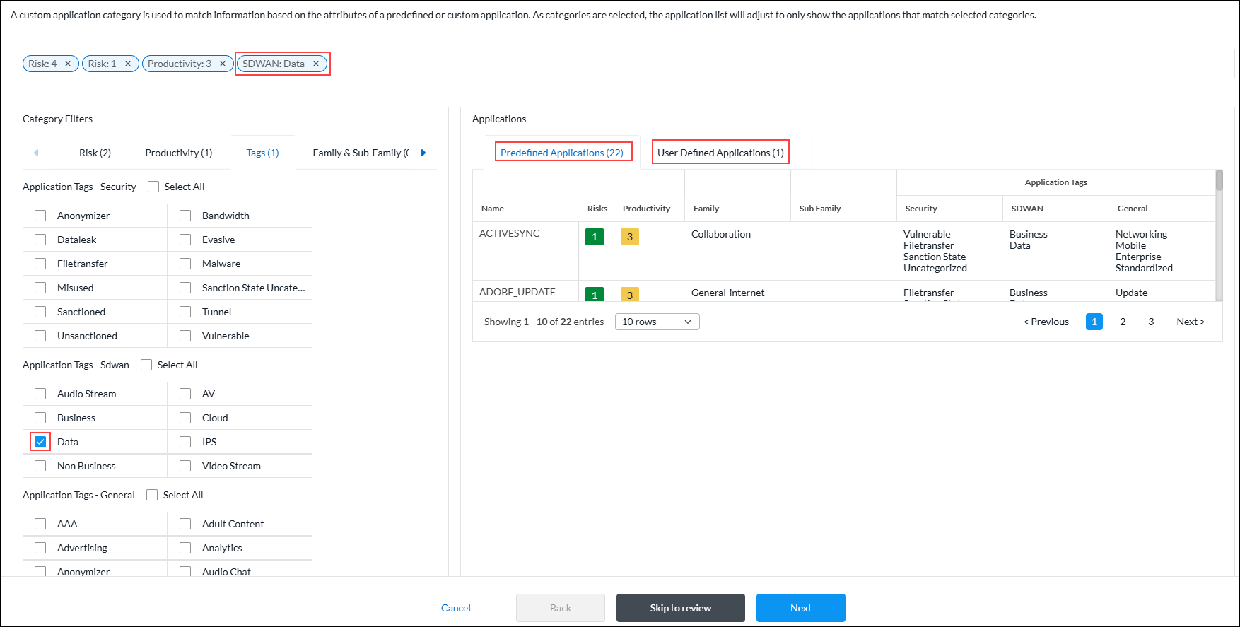
In this example screen, one application SD-WAN tag is selected. There are 22 predefined applications and 1 user-defined application, for a total of 23 applications that match all of the selected filters. This total matches the sum of the numbers displayed in the Predefined Applications (22) and User Defined Applications (1) tabs. - To customize the application family and sub-family filter, click the Family and Sub-Family tab in the Category Filters section, and then select one or more application filters.

In this example screen, one application family tag is selected. There is 1 predefined application and 1 user-defined application, for a total of 2 applications that match all of the selected filters. This total matches the sum of the numbers displayed in the Predefined Applications (1) and User Defined Applications (1) tabs. - Click Next to or select workflow step 2, Permissions.
- The permission for each role is selected by default, and you can update it. To change permissions for a role, select or deselect the Create, Read, Update, and Delete fields for the role.
- Click Next or select workflow step 3, Review and Submit.
- In the General section, enter a name for the reusable object. You can also enter a description and tags. A tag is an alphanumeric descriptor, with no white spaces or special characters, that you can use to search the objects.
- For all other sections, review the information. Click the Edit icon to make changes, if needed.
- Click Submit.
BGP Peer Policies
You can configure BGP peer policies to filter BGP routes, and then use them for configuring site-to-site tunnels. To filter routes that are received from remote BGP peers, you configure an import policy. To filter routes that are advertised to remote BGP peers, you configure an export policy.
You can configure BGP peer policies using one of the following methods:
- When you configure a policy that references BGP peer policies, you can click Add BGP Peer Policy to create a new BGP peer policy inline.
- Configure the BGP peer policy from the main menu. Then, when you configure a policy that references a BGP peer policy, you can select that BGP peer policy.
To create a BGP peer policy when you configure a policy, continue to Add a BGP Peer Policy, below.
To configure a BGP peer policy from the main menu:
- In Tenant view, select Configure > SD-WAN > Reusable Objects > BGP Peer Policies.
- If you have not yet configured a BGP peer policy, click Add BGP Peer Policy.
- If you have configured one or more BGP peer policies, the following screen displays. Click + Add.

- Continue to Add a BGP Peer Policy, below.
Add a BGP Peer Policy
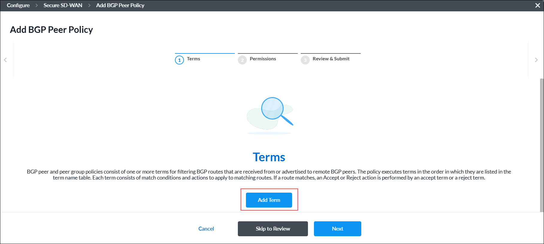
BGP peer and peer group policies consist of one or more terms for filtering BGP routes that are received from or advertised to remote BGP peers. The policy executes terms in the order in which they are listed in the term name table. Each term consists of match conditions and actions to apply to matching routes. If a route matches, an Accept or Reject action is performed by an accept term or a reject term.
Complete the following workflow to create a BGP peer policy.

- In workflow step 1, Terms, click Add Term.
-
Complete the following workflow to create a BGP peer policy term.

- In workflow step 1, Match Criteria, enter information for the following fields.

Field Description Policy Term Name (Required) Enter a name for the policy term. Community Enter the BGP community string to match. A BGP community is a group of destinations with a common property. This path attribute in BGP update messages identifies community members and performs actions at a group level instead of at an individual level. BGP communities help identify and segregate BGP routes, enabling smooth traffic flow. Extended Community Enter the extended BGP community string to match. In an extended community, you can group a larger number of destinations than in a community.
Range: 0000000000000000 to FFFFFFFFFFFFFFFF
Default: None
AS Path Enter the AS path number to match. Metric Enter the metric value to assign to the route.
Range: 0 through 4294967295IP Prefixes (NLRI) (Group of Fields) Enter information about the IPv4/IPv6 prefix. Click the  Plus icon to add additional IPv4/IPv6 prefixes. Click the
  Minus icon to remove IPv4/IPv6 prefixes.
- IPv4 Prefixes (Required)
Enter a valid IPv4 prefix, for example, 10.1.1.0/24. - Minimum Length
Enter the minimum prefix length to match. The minimum prefix length must be less than the maximum prefix length.
Range: 24 through 32
Default: None- Maximum Length
Enter the maximum prefix length to match. The minimum prefix length must be less than the maximum prefix length.
Range: 0 through 32
Default: None- Action (Required)
Select the action to take on the routes:
- Accept—Accept routes with this prefix.
- Reject—Reject routes with this prefix.
- IPv6 Prefixes (Required)
Enter a valid IPv6 prefix. For example, 2001::/24. - Minimum Length
Enter the minimum prefix length to match. The minimum prefix length must be less than the maximum prefix length.
Range: 32 through 128
Default: None- Maximum Length
Maximum Length—Enter the maximum prefix length to match. The minimum prefix length must be less than the maximum prefix length.
Range: 0 through 128
Default: None- Action (Required)
Select the action to take on the routes:
- Accept—Accept routes with this prefix.
- Reject—Reject routes with this prefix.
- Click Next or select workflow step 2, Action, and then enter information for the following fields.

Field Description Action (Group of Fields) - Action
Select the action to take on the routes:
- Accept
- Reject
- Local Preference
Enter the local preference value to use to choose the outbound external BGP path.
Range: 0 through 2147483647
- Enable ECMP for BGP Routes in RIB
Click the toggle to perform equal-cost multipath (ECMP) for BGP paths in the route table. BGP performs ECMP load balancing when two or more routes have the same administrative distance. - Administrative Distance
Enter an administrative distance value for routes learned from EBGP.
Range: 1 through 255
Default: None
- Metric Action
Select the metric action to take:
- Add
- IGP (interior gateway protocol)
- Set Value
- Subtract
- Metric
Enter a metric value. For IGP metric action, metric value is not applicable.
Range: 0 through 4294967295.
- Next Policy Term
Select the name of the next policy term to evaluate. You can use this field to create a sequence of terms, and then you use the Next Policy Term Action field to configure the sequence as an AND or OR series. - Next Policy Term Action
When you use the Next Policy Term field, select whether to create an AND series and an OR series:
- AND Series—Add this term to an AND series.
- OR Series—Add this term to an OR series.
Community (Group of Fields) - Community Action
Select how to match the community list for a route:
- Community field is ignored.
- Remove all communities from the route.
- Replace all communities with the single community specified by set-community.
- Remove all communities that match community value.
- Append the value of community value into the communities list.
- Community Action Value
Enter the community action value. The value should be a set of communities separated by a space in the format 2-byte decimal:2-byte decimal. Note that not all extended community actions require a community value.
Range: 0 through 65535
Default: None
- Extended Community Action
Select how to match the community list for a route:
- Community field is ignored.
- Remove all communities from the route.
- Replace all communities with the single community specified by set-community.
- Remove all communities that match community value.
- Append the value of community value into the communities list.
- Extended Community Action Value
Enter the BGP extended community action value. The extended community action value should be 16 characters.
Range: 0000000000000000 to FFFFFFFFFFFFFFFF
Default: None
AS Path (Group of Fields) - AS Path Action
Select a regular expression to match the AS path for the route:
- No AS path action.
- Prepend the local AS path the number of times specified by local AS prepend count.
- Remove all AS numbers matched by match as-path.
- Remove all AS numbers matched by match as-path and prepend the local AS the number of times specified by the local AS prepend count.
- AS Path Prepend
Select how to prepend the AS number to an AS path.
Range: 1 through 4294967295
Default: None
- Local AS Path Prepend Count
Enter the number of times to prepend the local AS number to the AS path.
Range: 1 through 255
Default: None
- Click Next or select workflow step 3, Review and Submit, and then enter information for the following fields.

Field Description Name (Required) Enter a name for the BGP peer policy term. Description Enter a description for the policy term. Tags Enter one or more tags. A tag is an alphanumeric text descriptor with no spaces or special characters. You can specify multiple tags added for the same object. The tags are used for searching the objects. Term Enabled Click the toggle to enable the policy term. - Review the settings you have selected. Click the
 Edit icon to change a setting, if needed.
 - Click Add Terms.
- In workflow step 1, Match Criteria, enter information for the following fields.
- Click Next or select workflow step 2, Permissions.
- The permission for each role is selected by default, and you can update it. To change permissions for a role, select or deselect the Create, Read, Update, and Delete fields for the role.
- Click Next or select workflow step 3, Review and Submit.
- In the General section, enter a name for the reusable object. You can also enter a description and tags. A tag is an alphanumeric descriptor, with no white spaces or special characters, that you can use to search the objects.
- For all other sections, review the information. Click the Edit icon to make changes, if needed.
- Click Submit.
Certificates
A certificate authority (CA) is a trusted third-party organization that issues electronic documents, called digital certificates. A CA certificate is a small data file issued by a CA that verifies a digital entity’s identity on the internet and indicates that the website is secured using an encrypted connection. CA certificates are an essential part of secure communication.
Versa Networks provides a set of self-signed trusted certificates that enable secure data transfer between web servers and the clients using secure socket layer (SSL) encryption. You can also add additional certificates, such as certificates for LDAP and IPsec tunnels.
A CA chain is an ordered list of the CA certificates for all trustworthy intermediate and end devices in a communications chain.
A private key is required to access secured traffic using a certificate. To secure the traffic on a Versa Operating SystemTM (VOSTM) device, you can use either a self-signed CA certificate or a trusted CA certificate.
You can create a certificate using one of the following methods:
- When you configure a profile that references certificates, you can click + Create New to create a new certificate inline.
- Create the certificate from the main menu. Then, when you configure a profile that references a certificate, you can select that certificate.
To create a certificate inline when you are configuring a profile, continue to Add a Certificate, below.
To create a certificate from the main menu:
- In Tenant view, select Configure > SD-WAN > Reusable Objects > Certificates.
The Certificates screen displays all currently available certificates, including the default Versa Cert certificate, which is supplied by Versa Networks, and the Versa CA Chain. - Click Add.

- Continue to Add a Certificate, below.
Add a Certificate
- To add a CA certificate, click CA Certificate, and then enter information for the following fields.
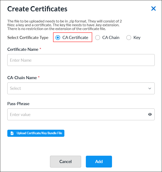
Field Description Certificate Name (Required) Enter a name for the certificate. CA Chain Name (Required) Select the CA chain name. Passphrase Enter a passphrase. Upload Certificate/Key Bundle File Click the  icon to upload the CA certificate file. The file must be in .zip format.
 - Click Add.
- To add a CA Chain certificate, click CA Chain, and then enter information for the following fields.
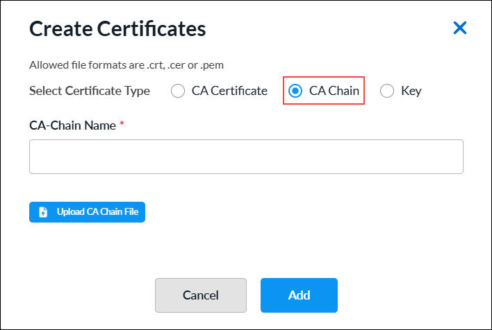
Field Description CA Chain Name (Required) Enter a name for the CA chain. Upload CA Chain File Click the  icon to upload the CA chain certificate file. The file must be in .cer, .crt, or .pem format.
 - Click Add.
- To add a private key file, click Key, and then enter information for the following fields.

Field Description Key Name (Required) Enter a name for the key file. Passphrase Enter a passphrase. Upload Key File Click the  icon to upload the private key file. The file must in be .pem or .key format.
 - Click Add.
DHCP Server Profiles
You can configure a VOS device to be a DHCP server by creating a DHCPv4 or DHCPv6 server profile. You associate a DHCP server profile with a DHCP server to define the properties of the server or with a global DHCP server to configure default profiles.
You configure reusable DHCP server profile objects using one of the following methods:
- When you configure a profile that references a DHCP server, you can click Add DHCPv4 Server to create a new DHCP server profile inline.
- Configure the DHCP server profile from the main menu. Then, when you configure a profile that references a DHCP server, you can select that DHCP server.
To create a DHCP server inline when you are configuring a profile, continue to Add a DHCPv4 or DHCPv6 Server Profile, below.
To configure a DHCP server profile from the main menu:
- In Tenant view, select Configure > SD-WAN > Reusable Objects > DHCP Server Profiles.
- If you have not yet configured a DHCP server profile:
- For DHCPv4, select DHCPv4 Server tab and click Add DHCPv4 Server.
- For DHCPv6, select DHCPv6 Server tab and click Add DHCPv6 Server.
- If you have configured one or more DHCP server profiles, the following screen displays. Select the DHCPv4 Server or DHCPv6 Server tab, and then Click + Add.

- If you have not yet configured a DHCP server profile:
- Continue to Add a DHCPv4 or DHCPv6 Server Profile, below.
Add a DHCPv4 or DHCPv6 Server Profile
Complete the following workflow to create a DHCPv4 or DHCPv6 server profile.
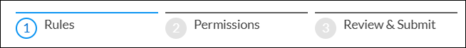
- In step 1, Rules, click + Add.

- To create a DHCPv4 or DHCPv6 server rule, see Create a DHCPv4 or DHCPv6 Server Rule.
- Click Next to go to step 2, Permissions.
- The permission for each role is selected by default, and you can update it. To change permissions for a role, select or deselect the Create, Read, Update, and Delete fields for the role.
- Click Next to go to step 3, Review and Submit.
- In the General section, enter a name for the reusable object. You can also enter a description and tags. A tag is an alphanumeric descriptor, with no white spaces or special characters, that you can use to search the objects.
- Click Submit.
Create a DHCPv4 or DHCPv6 Server Rule
Complete the following workflow to create a DHCPv4 server rule.

- In step 1, Match Criteria, enter information for the following fields.
For DHCPv4:

For DHCPv6:

Field Description Client Name Enter the name of the client from which DHCP messages are matched. Click the Add icon to add the client name to the list. Client Identifier Enter the name of the client. Click the Add icon to add the client identifier to the list. IPv4 Subnet Prefix For DHCPv4, enter the IPv4 subnet prefix to match. IPv6 Subnet Prefix For DHCPv6, enter the IPv6 subnet prefix to match. - Click Next or select workflow step 2, IP Pools and Name Servers, and then enter information for the following fields.

Field Description IP Pool Scope (Group of Fields) The IP pool scope is a range of valid IP addresses available for the DHCP server to assign to DHCP clients. Address Based Assignment
- Start Address
Enter the start IPv4 or IPv6 address of the IP address pool.
- End Address
Enter the end IPv4 or IPv6 address of the IP address pool.
- Exclude Addresses
Enter one or more IPv4 or IPv6 addresses to exclude.
Index Based Assignment - Start Index
Enter the start index for the DHCP pool. The start index is the index of the first host address in the DHCP pool. The start index is automatically computed by the system based on the LAN interface IP address subnet. For example, for a LAN interface with the address 192.168.0.1/24 and a start index of 2, the DHCP server pool starting address would be 192.168.0.2. - End Index
Enter the size of the DHCP address pool. The end address of the pool is measured using the LAN interface IP subnet, start index, and pool size. For example, for an interface with the address 192.168.0.1/24, start index 2, and pool size 250, the pool range would be 192.168.0.2 through192.168.0.251. - Exclude Indices
Enter a list of pool indexes to exclude. The list can be individual indexes or ranges, such as 67-90. The system automatically computes the exclude addresses in the IP subnet configured on the LAN interface. Name Servers Specify the name servers that are available for assignment to the DHCP client. You can add up to 5 name servers. - Name Server IP Address
Enter the IPv4 or Ipv6 address of the name server.
Domain - Domain Name
Enter the domain name of the DHCP service, such as versa-networks.com. Duplicate Address Detection (Group of Fields) - Enable
Click the toggle to enable the DHCP server to verify that an address is not currently in use before assigning it to a client. - Wait Time
Enter the wait time, in milliseconds.
Range: 100 through 5000- Number of Probes
Enter the number of probes.
Range: 0 through 5 - Click Next or select workflow step 3, IP Assignments/Reservations, and then enter information for the following fields.

Field Description Upload Mapping File Click the Upload Mapping File icon and select a mapping file to upload. Download Sample File Click the Download Sample File icon and select a sample file. Index Assignments To add a DHCP reservation:
- Click the + Add icon.
- In the Add IP Assignments screen, enter the following information.
- MAC Address—Enter the MAC Address of the DHCP client, for example 0d:56:45:52:53:41.
- Index—Enter the number of indexes to reserve in the IP address pool for the corresponding MAC addresses. The system will automatically compute reservations based on the IP subnet configured on the LAN interface. The number entered must be greater than 0.
- Description—Enter a description.

- Click Submit.
- Click Next or select workflow step 4, Lease Settings, and then enter information for the following fields.

Field Description Life Time Enter how long the lease profile is valid, in seconds.
Range: 60 through 31536000 seconds
Default: 3600 seconds
Renew Timer Enter the time during which a client can renew the lease profile. You can configure the renew timer to be less than or equal to 50 percent of the valid lifetime.
Range: 60 through 31536000 seconds
Default: 900 seconds
Rebind Timer Enter the time during which a rebind request can be sent by a client after a period of inactivity. The rebind timer can be configured <= 80 percent of the valid lifetime.
Range: 60 through 31536000 seconds
Default: 2800 seconds
Logging Click the slider bar to enable or disable the log utilization to generate the dhcp-pool-utilization alarm.
Click You must select Log Utilization to generate the dhcp-pool-utilization alarm.
- Low Threshold
Enter the lower value below which to log usage.
Range: 20 through 80 percent
Default: 80 percent
- High Threshold
Enter the upper value above which to log usage.
Range: 20 through 95 percent
Default: 95 percent
- Click Next or select workflow step 5, Advanced Options, and then enter information for the following fields.

Field Description DHCP Options (Group of Fields) - Key
Enter a number for the DHCP options key. - Type
Select an option type:
- Boolean
- FQDN
- IP Address
- IPv6 Address
- String
- uint8
- uint16
- uint32
- Hex String
- Vendor ID
Enter the vendor information if vendor information is exchanged between the DHCP server and client. - Value
Enter a value for the vendor ID, then click the Check icon to add the value. The value depends on the Option type you selected, as follows:
- Boolean—Enter true or false.
- FQDN—Enter a fully qualified domain name (FQDN).
- IP Address—Enter an IPv4 address.
- IPv6 Address—Enter an IPv6 address.
- String—Enter a text string.
- uint8—Enter a number from 0 through 255.
- uint16—Enter a number from 0 through 65535.
- uint32—Enter a number from 0 through 4294967295.
- Hex String—Enter a valid hexadecimal string.
Boot Options (Group of Fields) - Boot File Name
Enter the name of the file to use to boot the DHCP client. - Next Server
Enter a valid IP address of the next DHCP server in the boot sequence. - Echo Client ID
Click the slider bar to enable or disable the echo client ID option. The default is Enabled. NetBIOS Options (Group of Fields) - Name Server IP Address
Enter the IP address of the Windows Name Internet Server (WINS) to use for name resolution. - Type
Select the node type of name resolution:
- b—Broadcast. A b-node client sends the destination name in a broadcast message.
- h—Hybrid. An h-node client unicasts the destination name to the WINS server.
- m—Mixed. An m-node client broadcasts the destination name.
- p—Peer to peer. A p-node client sends the destination name in a unicast message to the WINS server.
- Click Next or select workflow step 6, Review and Submit, and then enter information for the following fields.
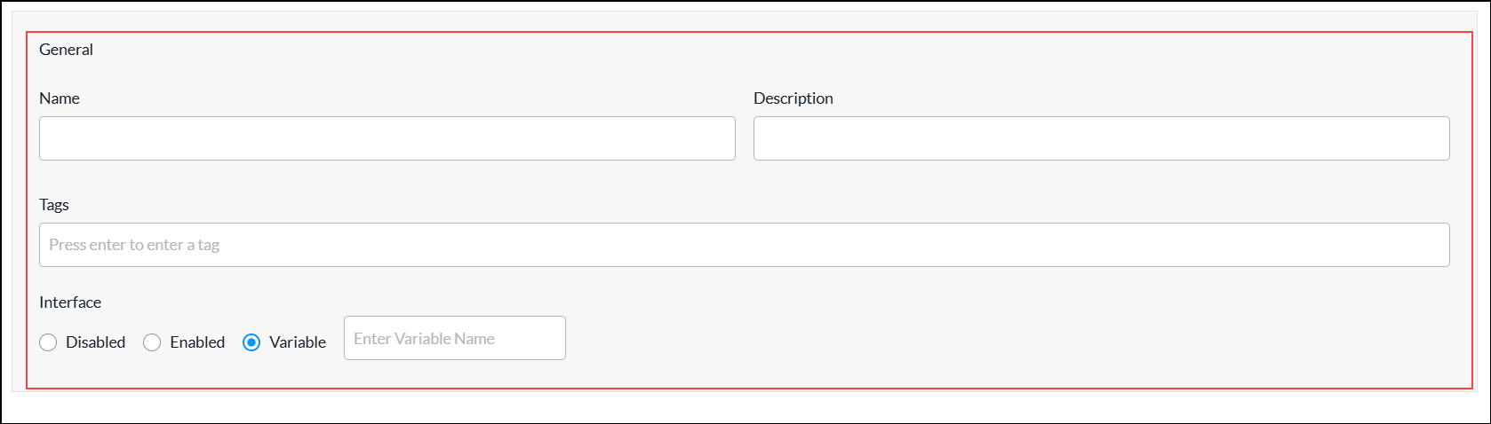
Field Description Name (Required) Enter a name for the DHCP server rule. Description Enter a description of the DHCP server rule. Tags Enter one or more tags. A tag is an alphanumeric text descriptor with no spaces or special characters. You can specify multiple tags added for the same object. The tags are used for searching the objects. Interface Click in the field and select an interface to use for the DHCP service.
Select the interface or network on which to match the client request
- Disabled—
- Enabled—
- Variable—
- Review the settings you have selected. Click the Edit icon to change a setting, if needed.
- Click Add DHCPv4 Server Rule or DHCPv6 Server Rule.
- Go to step 2 in the Add a DHCPv4 or DHCPv6 Server Profile section.
Files and Folders
When you want to configure policy for groups of IP addresses and URL categories and reputations objects, you can upload files that contain the addresses and URL information so that you do not have to configure these objects individually.
You can upload files that contain one or more IP addresses that you want to block (blacklist) or accept (whitelist). You can then associate the file with an address group and apply the address group to a security access policy. The IP addresses in the files must be in comma-separated valued (CSV) format, with each entry in the following format:
name, type, value
- name —Name of the address list
- type —Type of address: IPv4-prefix, IPv4-range, IPv6-prefix, or IPv6-range
- value—The IP address, subnet mask, or range
You can create files that contain one or more URLs and URL reputations and then upload the file while you are adding the URL category. To use a file when you are configuring URL categories objects, you create a CSV file and then upload it. The URL and its reputation in the files must be in CSV format, with each entry in one of the following formats:
- string,url,url-reputation
- patterns,regex-pattern,url-reputation
Manage Files and Folders
To upload an IP address file:
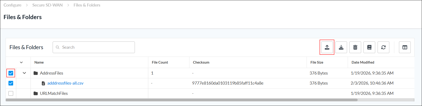
- In Tenant view, select Configure > SD-WAN > Reusable Objects > Files and Folders. The Files and Folders screen displays the uploaded address files and URL match files.
- Select the Address Files folder, and then click the
 Upload icon.
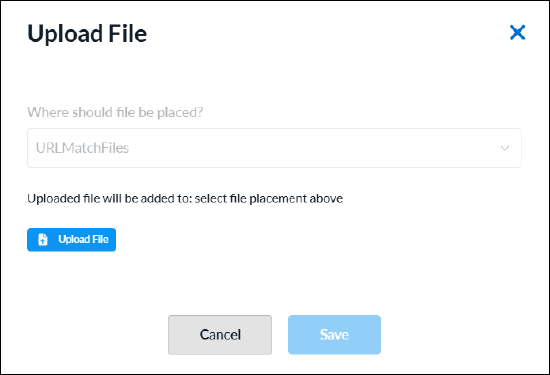
- In the Upload File screen, click the
 Upload File icon to upload an address file from the local system. The file must be in CSV format.

- Click Save. The uploaded address file displays in the Address Files folder.
- To download an IP address file:
- Select the address file.
- Click the
 Download icon.
 - Save the CSV file to the local system.
- To delete an IP address file:
- Select the address file.
- Click the
 Delete icon.
 - In the delete screen, select Permanently Delete [item type].

- To display an address file reference, select the address file, and then click the
 View References icon. The View References for Address Files screen displays the references for the selected address file.

To upload a URL match file:
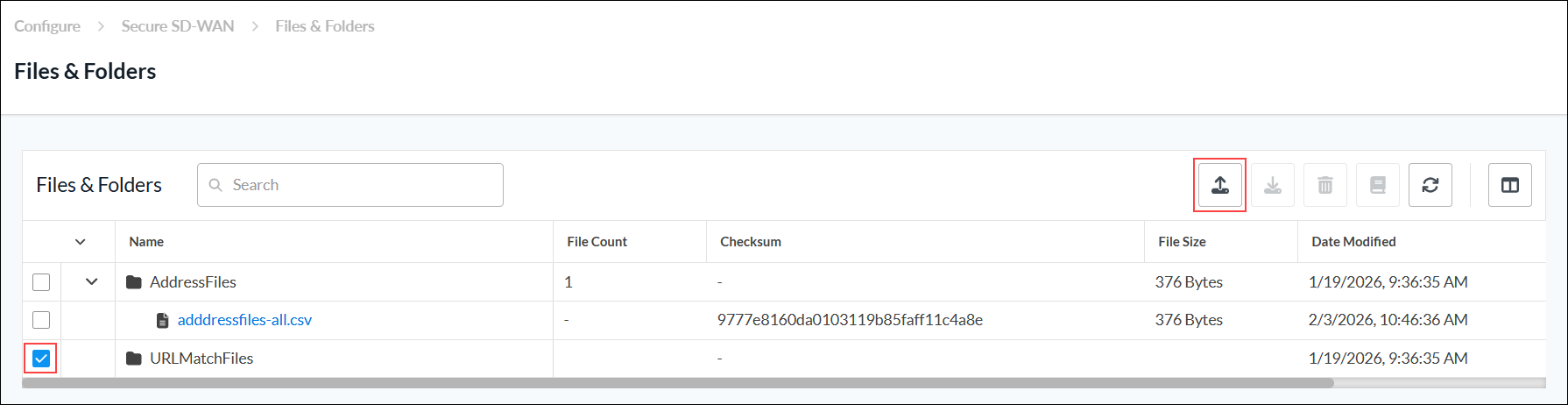
- Go to Configure > SD-WAN > Reusable Objects > Files and Folders. The Files and Folders screen displays the uploaded address files and URL match files.
- Select the URL Match Files folder, and then click the Upload icon.
- In the Upload File screen, click the Upload File icon to upload a URL match file from local system. The file must be in CSV format.
- Click Save. The uploaded URL match file displays in the URL Match Files folder.
- To download a URL match file:
- Select the URL file.
- Click the Download icon.
- Save the CSV file to the local system.
- To delete a URL match file:
- Select the URL file.
- Click the Delete icon.
- In the delete screen, select Permanently Delete [item type].
- To display a URL match file references, select the URL match file, and the nclick the
 View References icon. The View References for URL match file screen displays the references for the selected URL match file.
Interface Schedulers
You can configure QoS interface schedulers to assign traffic class schedulers to QoS forwarding class categories using one of the following methods:
- When you configure a profile that references interface schedulers, you can click + Create New to create a new interface scheduler inline.
- Configure the interface scheduler from the main menu. Then, when you configure a profile that references an interface scheduler, you can select that interface scheduler.
To configure an interface scheduler inline when you are configuring a profile, continue to Configure an Interface Scheduler, below.
To configure an interface scheduler from the main menu:
- In Tenant view, select Configure > SD-WAN > Reusable Objects > Interface Schedulers.
- If you have not yet configured an Interface Scheduler, click Add Interface Scheduler.
- If you have configured one or more interface schedulers, the following screen displays. Click
 Add.
Add.

- Continue to Configure an Interface Scheduler, below.
Configure an Interface Scheduler
Complete the following workflow to add an interface scheduler.
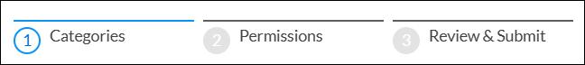
- In step 1, Categories, select the tab for the forwarding class you want to configure. You can configure more than one tab before moving to next step.
- Assured forwarding
- Best effort
- Expedited forwarding
- Network control
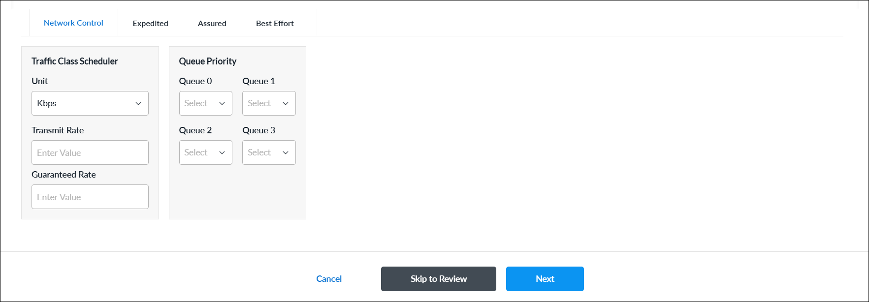
- Enter information for the following fields.
Field Description Forwarding Class Select any tab for the forwarding class:
- Assured forwarding
- Best effort
- Expedited forwarding
- Network control
Traffic Class Scheduler (Group of Fields) - Unit
Select a unit to set the transmission and guaranteed rates for data packets:
- Kbps—Enter the rate of data packets.
- Percent (%)—Enter the rate of data packets as a percentage of the line bandwidth rate or of the parent interface’s shaping rate.
- Transmit Rate
Set the transmission rate of data packets:
-
For Kbps unit, enter the transmission rate of data packets.
Range: 8 through 100000000 Kbps
Default: None -
For % unit, enter the transmission rate of data packets as a percentage of the line bandwidth rate or of the parent interface’s shaping rate.
Range: 1 through 100 percent
Default: None
Guaranteed Rate Set the guaranteed transmission rate of data packets:
-
For Kbps unit, enter the guaranteed transmission rate of data packets.
Range: 8 through 100000000 Kbps
Default: None -
For % unit, enter the guaranteed transmission rate of data packets as a percentage of the line bandwidth rate or of the parent interface’s shaping rate:
Range: 1 through 100 percent
Default: None
Queue Priority Select a priority to assign for each queue. Traffic can be assigned to the following different queues:
- Queue 0
- Queue 1
- Queue 2
- Queue 3
Range: 1 through 16.
- Click Next or select workflow step 2, Permissions.
- The permission for each role is selected by default, and you can update it. To change permissions for a role, select or deselect the Create, Read, Update, and Delete fields for the role.
- Click Next or select workflow step 3, Review and Submit.
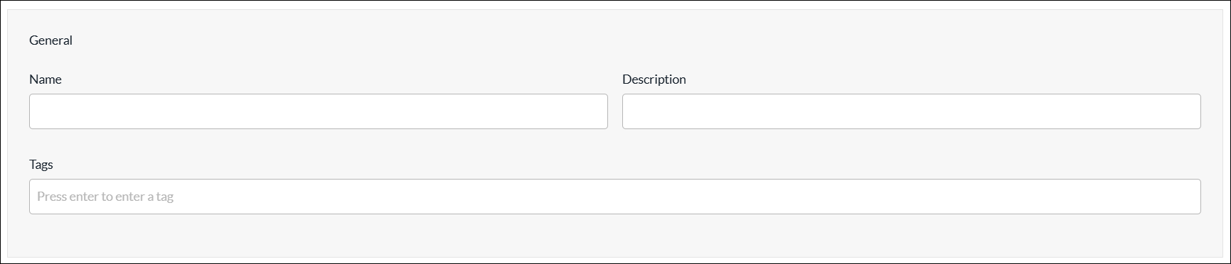
- In the General section, enter a name for the reusable object. You can also enter a description and tags. A tag is an alphanumeric descriptor, with no white spaces or special characters, that you can use to search the objects.
- Review the settings you have selected. Click the Edit icon to change a setting, if needed.
- Click Submit.
IP SLA Monitors
IP service-level agreement (SLA) monitoring is a method of actively and continuously monitoring traffic across the network and reporting about the traffic. You can monitor an IP address or a fully qualified domain name (FQDN) by configuring an IP SLA monitor object and then associating the object with the IP address or FQDN. To verify whether the IP address or FQDN is up or down, the IP SLA monitor sends either DNS, HTTP and HTTPS, ICMP or TCP probe packets.
You can configure IP SLA monitor objects using one of the following methods:
- When you configure a profile that references IP SLA monitor objects, you can click + Create New to create a new IP SLA monitor object inline.
- Configure the IP SLA monitor from the main menu. Then, when you configure a profile that references an IP SLA monitor, you can select that IP SLA monitor.
To configure an IP SLA monitor object inline when you are configuring a profile, continue to Add an IP SLA Monitor Object, below.
To configure an IP SLA monitor object from the main menu:
- In Tenant view, select Configure > SD-WAN > Reusable Objects > IP SLA Monitors.
- If you have not yet configured an IP SLA Monitor object, click Add IP SLA Monitor.
- If you have configured one or more IP SLA monitor objects, the following screen displays. Click + Add.
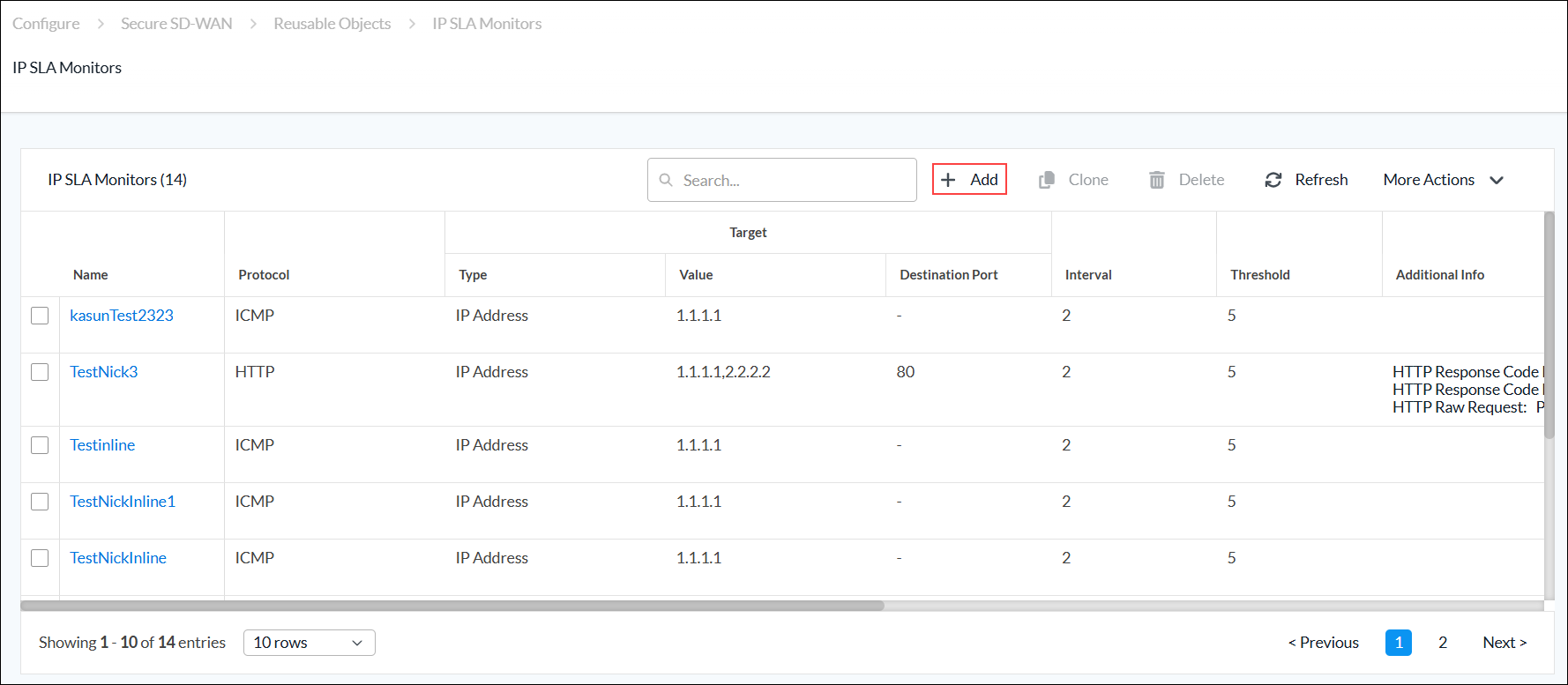
- Continue to Add an IP SLA Monitor Object, below.
Add an IP SLA Monitor Object
Complete the following workflow to add an IP SLA monitor object.

- In step 1, Categories, enter information for the following fields.

Field Description Monitor Protocol
Select the type of packets to send to the IP address:
- DNS
- HTTP
- HTTPS
- ICMP
- TCP
Domain Name (Required)
For DNS protocol, and if you configure an FQDN, enter the domain name for the IP SLA monitor. HTTP Response Code Low (Required)
For HTTP and HTTPS protocols, enter the lowest value of the status code range. HTTP Response Code High (Required)
For HTTP and HTTPS protocols, enter the highest value of the status code range. HTTP Raw Request
For HTTP raw monitors, enter the HTTP request string to send generic HTTP requests to the remote endpoint. The string must include the complete HTTP request and the host attribute. For example, if you issue the HTTP request GET /vpntest HTTP/1.0\r\nUser-Agent:Versa IP SLA\r\nHost:httpserver.com\r\n\r\n;, the monitor sends a GET request to the httpserver.com to retrieve information.
Destination Port
For DNS, HTTP, HTTPS, and TCP protocols, enter the destination port for the IP SLA monitor. For TCP, this is a mandatory field. Target Type Click to configure one or more IP addresses or FQDNs to monitor:
- IP Address
- FQDN
- IP Address (Required)
Select IP Address, and then enter the IP address to monitor. If you select more than one IP address, all the IP addresses must be reachable for the IP monitor to be applied (this is an AND condition). - FQDN (Required)
Select FQDN, and then enter one or more FQDNs to monitor. Interval Enter the frequency, in seconds, at which to send ICMP packets to the IP address.
Range: 1 through 60 seconds
Default: 3 seconds
Threshold Enter the maximum number of ICMP packets to send to the IP address. If the IP address does not respond after this number of packets, the monitor object and IP address are marked as down.
Range: 1 through 60
Default: 5
Forwarding Class Select a forwarding class for the IP SLA monitor to override the default forwarding class. Next Hop Appliance Select the device to use as the next hop. Source Type - Source Network
Select the source interface on which to send the probe packets. This interface determines the routing instance through which to send the probe packets. This routing instance is the target routing instance for the probe packets. - Source Routing Instance
Select the routing instance for the monitor object to use to reach the target IP addresses and FQDNs. - Click Next to go to step 2, Permissions.
- The permission for each role is selected by default, and you can update it. To change permissions for a role, select or deselect the Create, Read, Update, and Delete fields for the role.
- Click Next to go to step 3, Review and Submit.
- In the General section, enter a name for the reusable object. You can also enter a description and tags. A tag is an alphanumeric descriptor, with no white spaces or special characters, that you can use to search the objects.
- Click Submit.
IP SLA Monitor Groups
You can create an IP SLA monitor group using one of the following methods:
- When you configure a profile that references an IP SLA monitor group, you can click + Create New to create a new IP SLA monitor group inline.
- Configure the IP SLA monitor group from the main menu. Then, when you configure a profile that references an IP SLA monitor group, you can select that monitor group.
To create an IP SLA monitor group inline when you are configuring a profile, continue to Add an IP SLA Monitor Group, below.
To configure an IP SLA monitor group from the main menu:
- In Tenant view, select Configure > SD-WAN > Reusable Objects > IP SLA Monitor Groups.
- If you have not yet configured an IP SLA Monitor Group, click Add IP SLA Monitor Group.
- If you have configured one or more IP SLA monitor groups, the following screen displays. Click + Add.
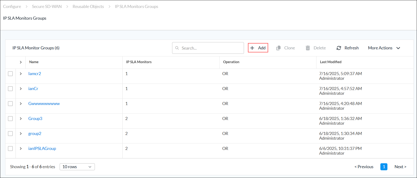
- Continue to Add an IP SLA Monitor Group, below.
Add an IP SLA Monitor Group
Complete the following workflow to add an IP SLA monitor group.

- In step 1, IP SLA Monitor, select the operation that you want to assign to the new group:
- OR—If any member of the group is reachable, the entire group is considered reachable.
- AND—If any one member monitor becomes unreachable, the entire group is considered unreachable.
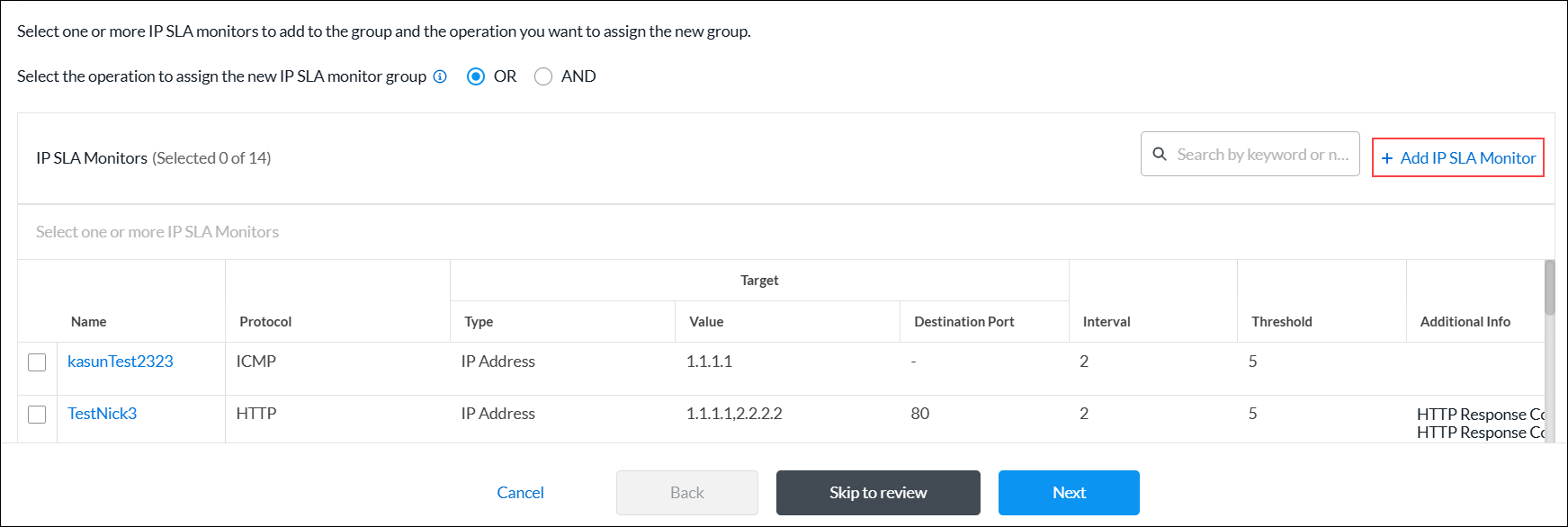
- In the IP SLA Monitors list, select one or more IP SLA monitors to add to the group. To add a new IP SLA Monitor, click + Add IP SLA Monitor. For more information, see Add an IP SLA Monitor Object.
- Click Next to go to step 2, Permissions.
- The permission for each role is selected by default, and you can update it. To change permissions for a role, select or deselect the Create, Read, Update, and Delete fields for the role.
- Click Next to go to step 3, Review and Submit.
- In the General section, enter a name for the reusable object. You can also enter a description and tags. A tag is an alphanumeric descriptor, with no white spaces or special characters, that you can use to search the objects.
- Click Submit.
Logging Profiles
You can create a custom logging profile to forward logs to a Versa Analytics cluster or 3rd-party system.
When you configure a logging profile, you select collectors and collector groups:
- Collector—A collector contains information for a single logging destination. The destination differs depending on whether you are sending the logs to a Versa Analytics cluster or a third-party system:
- Versa Analytics clusters—For Versa Analytics clusters, including clusters in the Versa Advanced Logging Service (ALS), the destination is the IP address, protocol, and port number for an application delivery controller (ADC) service on a Versa Controller node. The ADC service distributes the logs to the nodes in the Analytics cluster using a load-balancing method. The ADC service must be configured on a Controller node in your DCA complex, which is typically done by the service provider using Versa Director. Analytics nodes can accept logs in IPFIX format only. For more information about ADCs, see Configure an Application Delivery Controller. and Configure the Versa Advanced Logging Service.
- Third-party systems—The destination can be the IP address, protocol, and port number for a third-party system that is reachable from a specific LAN or WAN network. Alternately, the destination can be an ADC service that is configured to forward logs to a third-party system. You can forward the logs in either IPFIX or Syslog format.
- Collector Group—A collector group is a list of one or more collectors. One collector in the group is chosen to be the active collector for the group. If the active collector becomes unreachable, then another collector in the group becomes the active collector. If you configure only a single collector group then logs are sent to a single destination. If you configure multiple collector groups, then the active collector for each group is sent a copy of the logs.
You can configure a logging profile using one of the following methods:
- When you configure a profile that references a logging profile, you can click + Create New to create a new logging profile inline.
- Configure the logging profile from the main menu. Then, when you configure a profile that references a logging profile, you can select that logging profile.
To create a logging profile inline when you are configuring a profile, continue to Create a Logging Profile, below.
To configure a logging profile from the main menu:
- In Tenant view, select Configure > SD-WAN > Reusable Objects > Logging Profiles.
- If you have not yet configured a logging profile, click Add Collector Group.
- If you have configured one or more logging profiles, the following screen displays. Click + Add.

- Continue to Create a Logging Profile, below.
Create a Logging Profile
Complete the following workflow to add a logging profile.
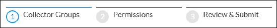
- In step 1, Collector Groups, click Add Collector Group.
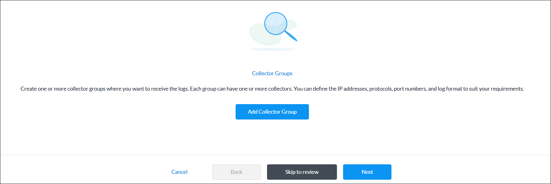
- In the Add Collector Groups screen, enter information for the following fields.
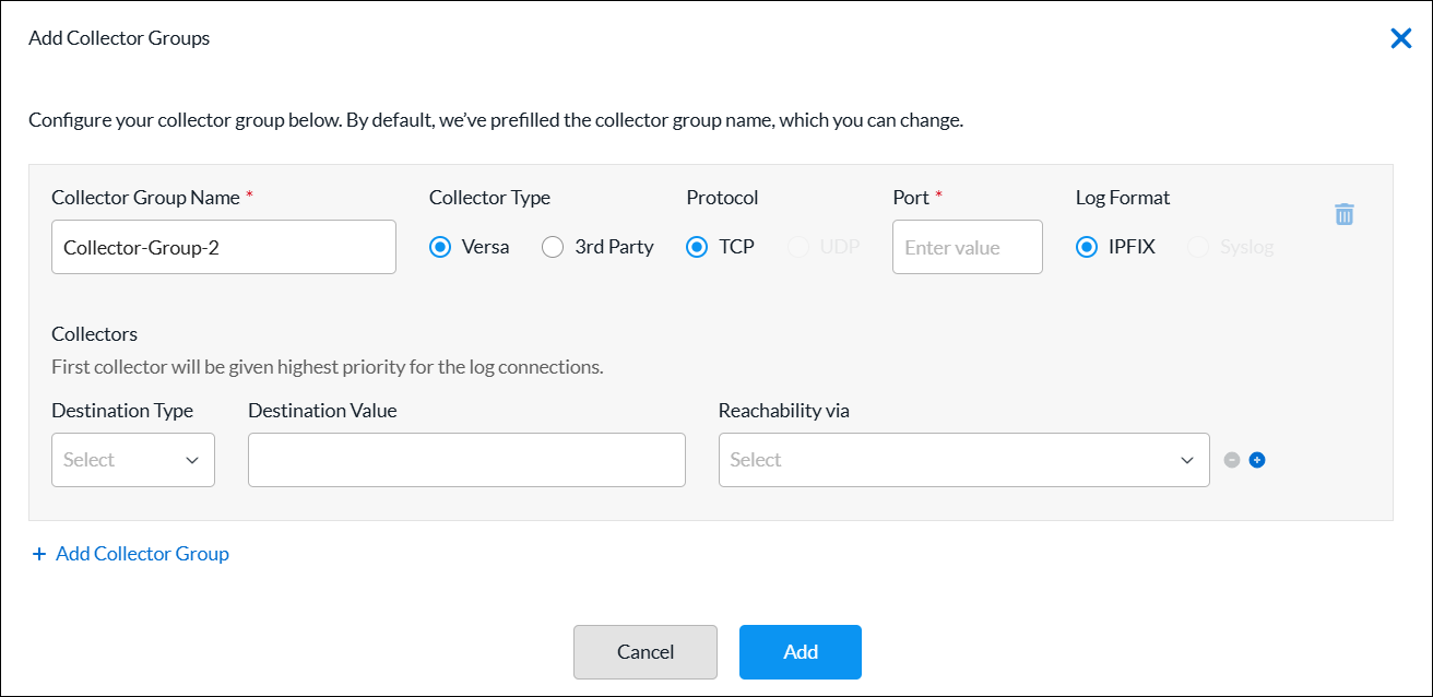
Field Description Collector Group Name (Required) By default, the collector group name is prefilled. You can change the the collector group name. Collector Type Select the collector type:
- Versa—Select to send logs to a Versa Analytics cluster.
- Third-party—Select to send logs to a 3rd-party system.
Protocol (For the third-party collector type only.) Select a protocol:
- TCP
- UDP
Note: For the Versa collector type, the TCP protocol is preselected and cannot be changed.
Port (Required) Enter the port number of the destination. Log Format (For the third-party collector type only.) Select a log format:
- IPFIX
- Syslog
Note: For the Versa collector type, the IPFIX format is preselected and cannot be changed.
Collectors (Group of Fields) The first collector is given highest priority for the log connections. - Destination Type
Select the destination type, and then enter a destination value for the collector:
- IP Address—Enter the IP address of the destination.
- FQDN—Enter the FQDN of the destination.
- Reachability Via
Select the method used to reach the destination. For Controllers, the destination must be an ADC service configured on the controller.
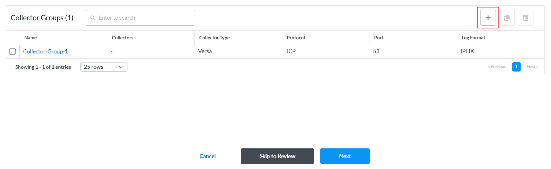
+ Add Collector Group Click to add a new collector group and collector. - Click Add. The Collector Groups list displays the log collector group added.
- To view the log collector group details, click the
 Eye icon.
 - To add a new log collector group, click + Add.
- To view the log collector group details, click the
- Click Next to go to step 2, Permissions.
- The permission for each role is selected by default, and you can update it. To change permissions for a role, select or deselect the Create, Read, Update, and Delete fields for the role. Permissions apply to the logging profile.
- Click Next to go to step 3, Review and Submit.
- In the General section, enter a name for the reusable object. You can also enter a description and tags. A tag is an alphanumeric descriptor, with no white spaces or special characters, that you can use to search the objects.
- Click Submit.
Rewrite Rules
You configure rewrite rules to rewrite the quality of service (QoS) bits in the header of outgoing packets. A rewrite rule examines a packet's forwarding class and loss priority and sets the header bits to the values defined in the rule. Rewrite rules apply the packet loss priority and forwarding class information to determine the Differentiated Services Code Point (DSCP) on outbound packets or streams.
You can configure a rewrite rule using one of the following methods:
- When you configure a profile that references rewrite rules, you can click + Create New to create a new rewrite rule inline.
- Configure the rewrite rule from the main menu. Then, when you configure a profile that references a rewrite rule, you can select that rewrite rule.
To create a rewrite rule inline when you are configuring a profile, continue to Add a Rewrite Rule, below.
To configure a rewrite rule from the main menu:
- In Tenant view, select Configure > SD-WAN > Reusable Objects > Rewrite Rules.
- If you have not yet configured a rewrite rule, click Add Rewrite Rules.
- If you have configured one or more rewrite rules, the following screen displays. Click + Add.

- Continue to Add a Rewrite Rule, below.
Add a Rewrite Rule
Complete the following workflow to add a rewrite rule.

- In step 1, Settings, enter information for the following fields.
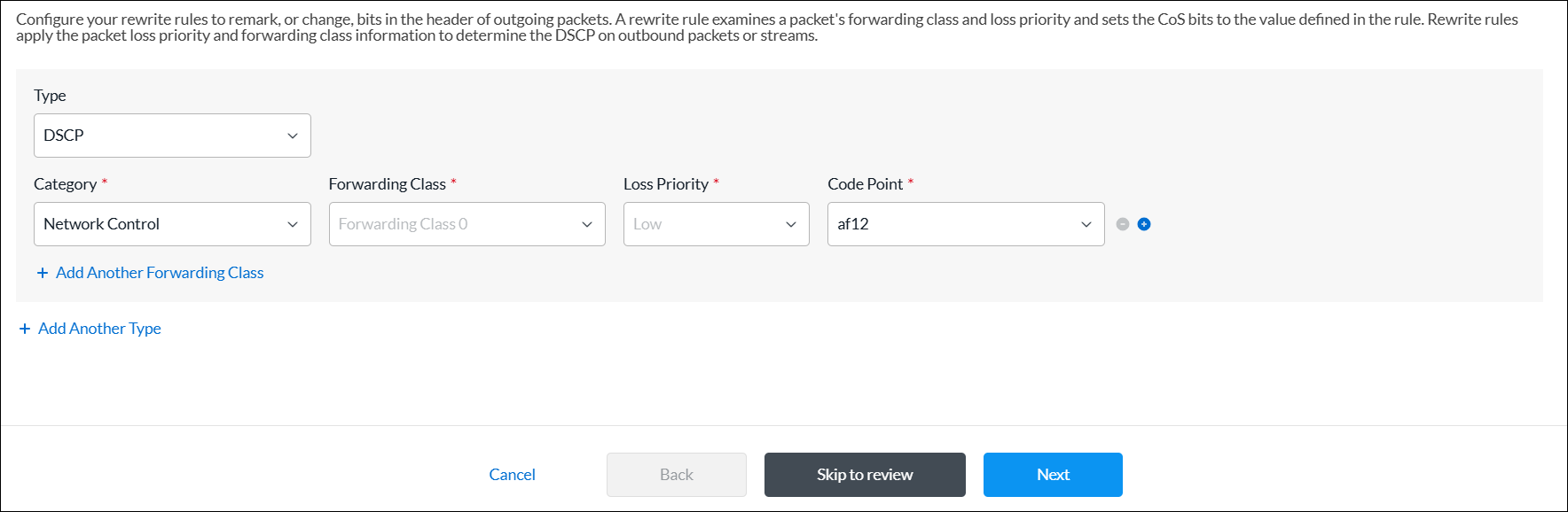
Field Description Type Select the rewrite table type:
- DSCP
- DSCP IPv6
- IEEE 802.1p
Category (Required) Select the category:
- Assured
- Best Effort
- Expedited
- Network Control
Forwarding Class (Required) Select the forwarding class to which to apply the rewrite rule. Certain forwarding classes are available for each category:
- Forwarding Class 0 through Forwarding Class 3 (for the Network Control category)
- Forwarding Class 4 through Forwarding Class 7 (for the Expedited category)
- Forwarding Class 8 through Forwarding Class 11 (for the Assured category)
- Forwarding Class 12 through Forwarding Class 15 (for the Best Effort category)
Loss Priority (Required) Select the drop loss priority at which the DSCP, DSCP IPv6, or IEEE 802.1p value should be rewritten:
- Low
- High
Code Point (Required) Select the standard code point to associate with the forwarding class and the drop loss priority. + Add Another Forwarding Class Click to add another forwarding class, if needed. + Add Another Type Click to add another type, if needed. - Click Next to go to step 2, Permissions.
- The permission for each role is selected by default, and you can update it. To change permissions for a role, select or deselect the Create, Read, Update, and Delete fields for the role.
- Click Next to go to step 3, Review and Submit.
- In the General section, enter a name for the reusable object. You can also enter a description and tags. A tag is an alphanumeric descriptor, with no white spaces or special characters, that you can use to search the objects.
- Click Submit.
Routing Instance Names
You can create a routing instance name using one of the following methods:
- When you configure a profile that references a routing instance, you can click + Create New to create a new routing instance name inline.
- Configure the routing instance name from the main menu. Then, when you configure a profile that references a routing instance, you can select that routing instance name.
To create a routing instance name inline when you are configuring a profile, continue to Create Routing Instance Names, below.
To configure a routing instance name from the main menu:
- In Tenant view, select Configure > SD-WAN > Reusable Objects > Routing Instance Names.
- If you have not yet configured a routing instance name, click + Add Routing Instance Name.
- If you have configured one or more routing instance names, the following screen displays. Click + Add.

- Continue to Create Routing Instance Names, below.
Create Routing Instance Names
- In the Create Routing Instance Names screen, enter information for the following fields.

Field Description Routing Instance Name Enter a name for the routing instance. Guest Disabled Click the toggle to enable the interface for guests. When enabled, this VPN interface does not participate in the topology. Only direct internet access (DIA) is provisioned.
Default: Disabled
Description Enter a description for the routing instance. - Click Add.
SaaS Application Monitors
You configure SaaS application monitors to perform SD-WAN performance-based path selection. SaaS application monitors check the liveness of an application using each next hop, and they also monitor application performance. While you can use performance-based path selection for any application, you typically use it in the context of selecting the best path to cloud-based SaaS applications.
In an SD-WAN network, a tenant or organization can reach a SaaS application using multiple WAN links directly, or using some other SD-WAN appliance (typically hubs). These WAN links can use different paths and even different transport networks, such as MPLS, internet, LTE, and satellite links. Because the transmission latency among different paths can vary, it is important to choose the best available path for optimal SaaS-application performance.
To configure SaaS application monitoring, you configure VOS devices to send HTTP, ICMP, and TCP probes. These active monitoring probes measure the responsiveness of commonly-used cloud-based SaaS applications.
You can configure SaaS application monitors using one of the following methods:
- When you configure a profile that references SaaS application monitors, you can click + Create New to create a new SaaS application monitor inline.
- Configure the SaaS application monitor from the main menu. Then, when you configure a profile that references a SaaS application monitor, you can select that SaaS application monitor.
To add a SaaS application monitor inline when you are configuring a profile, continue to Add SaaS Application Monitors, below.
To add a SaaS application monitor from the main menu:
- In Tenant view, select Configure > SD-WAN > Reusable Objects > SaaS Application Monitors.
- If you have not yet configured a SaaS application monitor, click + Add SaaS Application Monitor.
- If you have configured one or more SaaS application monitors, the following screen displays. Click + Add.

- Continue to Add SaaS Application Monitors, below.
Add SaaS Application Monitors
Complete the following workflow to add a SaaS application monitor.

- In step 1, Monitor Destination, enter information for the following fields.
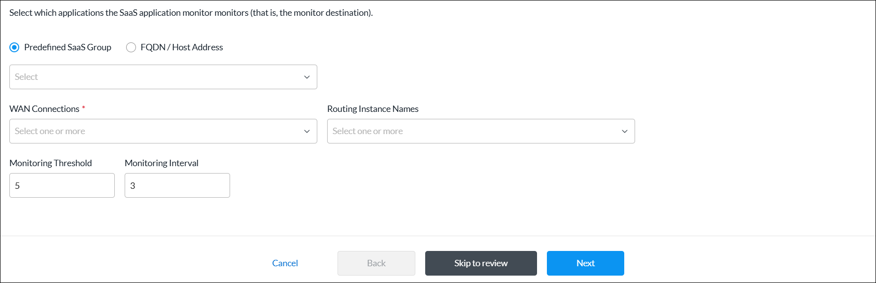
Field Description Predefined SaaS Group Click to use the SaaS application monitor to monitor a predefined set of SaaS applications, and then select the group.
FQDN/Host Address Click to use the SaaS application monitor to monitor applications using a specific domain or host address as the monitor destination, and then enter the FQDN or host address. WAN Connections (Required) Select one or more WAN connections to monitor SaaS applications. Routing Instance Names Select one or more routing instances to monitor SaaS applications. Monitoring Threshold Enter a value for the monitoring threshold. This value indicates the number of consecutive monitor probes that can be lost or unresponsive before declaring the application monitor down.
Range: 1 through 60
Default: 5
Monitoring Interval Enter how often, in seconds, to send monitoring probes.
Range: 1 through 60 seconds
Default: 3 seconds
- Click Next to go to step 2, Monitor Protocol, and enter information for the following fields.
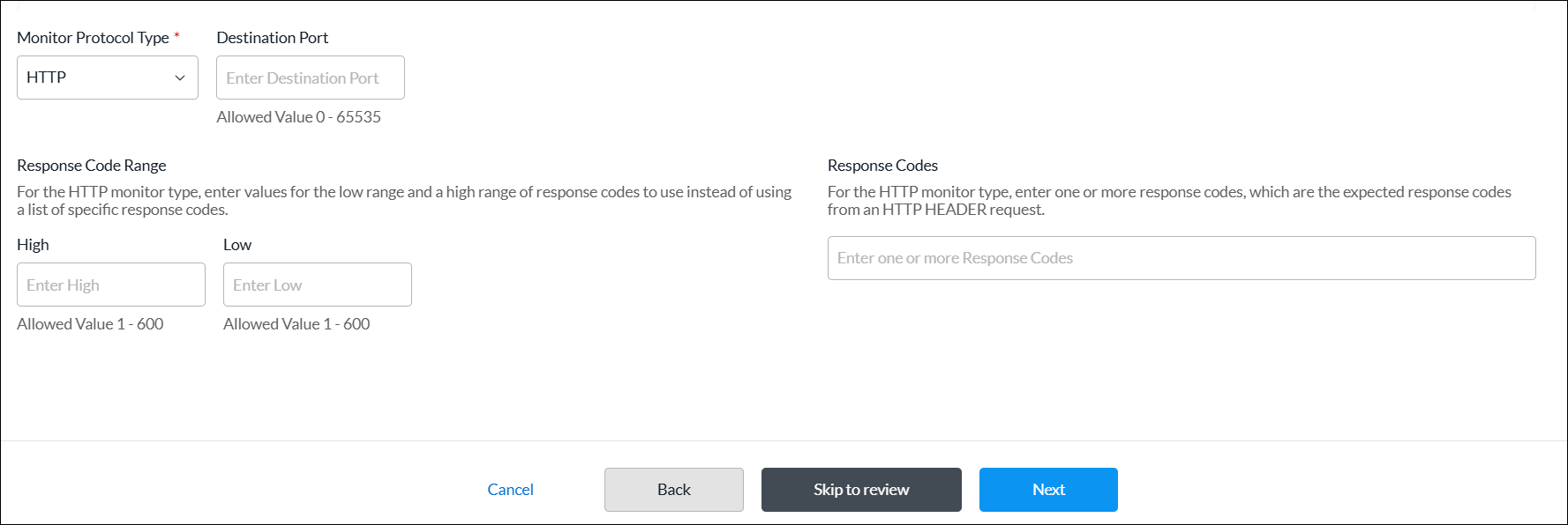
Field Description Monitor Protocol Type (Required) Select a protocol type to use to monitor SaaS applications:
- ICMP
- HTTP
- TCP
Destination Port For the HTTP and TCP monitor types, enter the port number on which the application monitor is located.
Range: 0 through 65535
Default: None
Response Code Range (Group of Fields) For the HTTP monitor type, enter the high and low values for the range of response codes to use instead of using a list of specific response codes. - Low
Enter the low value of the response code range. The low value should be less than or equal to the high value.
Range: 1 through 600
Default: None
- High
Enter the high value of the response code range. The high value should be greater than or equal to the low value.
Range: 1 through 600
Default: None
Response Codes For the HTTP monitor type, enter one or more response codes, which are the expected response codes from an HTTP header request. If the received response code does not match one in the list, the monitor is declared to be down. - Click Next to go to step 3, Consuming Tenants, and enter information for the following fields.
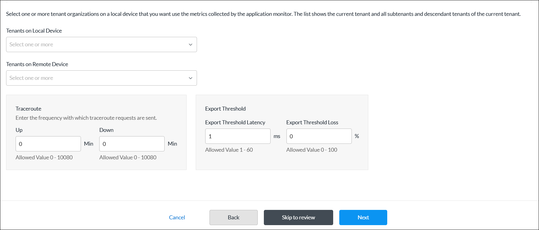
Field Description Tenants on Local Device Select one or more tenant organizations on a local device that you want to use the metrics collected by the application monitor. The list shows the current tenant and all its subtenants and descendant tenants. Tenants on Remote Device Select one or more tenant organizations on a remote device that you want to use the metrics collected by the application monitor. Traceroute (Group of Fields) Enter the frequency at which traceroute requests are sent. - Up Interval
Enter the traceroute repeat interval for when the monitor state is up, in minutes. To disable traceroute when the monitor is up, configure an interval value of 0.
Range: 0 through 10080 minutes
Default: None
Recommended Value: 60 minutes (1 hour)- Down Interval
Enter the traceroute repeat interval for when the monitor state is down, in minutes. To disable traceroute when the monitor is down, configure an interval value of 0.
Range: 0 through 10080 minutes
Default: None
Recommended Value: 15 minutesExport Threshold (Group of Fields) - Export Threshold Latency
Enter a latency change time, in milliseconds, to reach before the application monitor exports a new latency metric. For example, if the application monitor measures the latency as 10 milliseconds, with the default export threshold of 5 milliseconds, the metric is updated and exported when the latency reaches 15 milliseconds (10 + 5).
Range: 1 through 60 milliseconds
Default: 5 milliseconds- Export Threshold Loss
Enter the amount of loss, as a percentage, to reach before the application monitor exports a new latency metric.
Range: 1 through 100 percent
Default: 2 percent
- Click Next to go to step 4, Permissions.
- The permission for each role is selected by default, and you can update it. To change permissions for a role, select or deselect the Create, Read, Update, and Delete fields for the role.
- Click Next to go to step 5, Review and Submit.
- In the General section, enter a name for the reusable object. You can also enter a description and tags. A tag is an alphanumeric descriptor, with no white spaces or special characters, that you can use to search the objects.
- Click Submit.
Schedule Objects
Security policy rules work at all dates and times. You can define a schedule object to limit a security policy to specific times. Schedule objects can match criteria based on time of day. For example, you can define a policy rule that is effective only during certain times of the day, such as lunch hours or after standard working hours. You can specify schedule objects for a fixed date and time range, or for a recurring daily or weekly schedule.
Schedule objects that you configure for a tenant are applicable for that tenant only, and they are not visible to other tenant in the system.
You can configure a schedule object using one of the following methods:
- When you configure a profile that references schedule objects, you can click + Create New to create a new schedule object inline.
- Configure the schedule object from the main menu. Then, when you configure a profile that references a schedule, you can select that schedule object.
To create a schedule object inline when you are configuring a profile, continue to Add a Schedule, below.
To configure a schedule object from the main menu:
- In Tenant view, select Configure > SD-WAN > Reusable Objects > Schedules.
- If you have not yet configured a schedule, click + Add Schedule.
- If you have configured one or more schedules, the following screen displays. Click + Add.

- Continue to Add a Schedule, below.
Add a Schedule
Complete the following workflow to add a schedule.

- In step 1, Recurrence and Time Interval, enter information for the following fields.
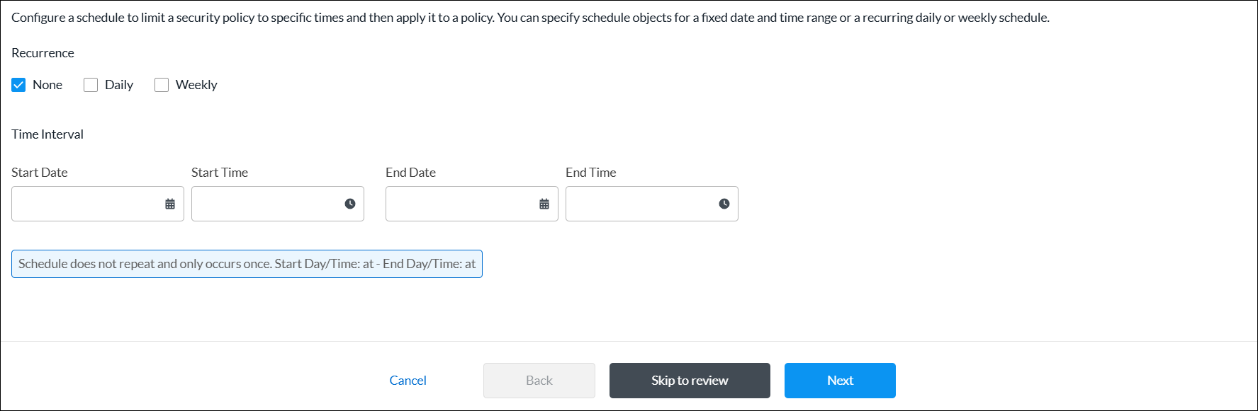
Field Description Recurrence Select the type of schedule:
- None—Specify the start and end date and time.
- Daily—Select all day, or specify a start and end time in 24-hour format (HH:MM).
- Weekly—Select a day of the week, and then select all day or specify the start and end time in 24-hour format (HH:MM).
- Click Next to go to step 2, Permissions.
- The permission for each role is selected by default, and you can update it. To change permissions for a role, select or deselect the Create, Read, Update, and Delete fields for the role.
- Click Next to go to step 3, Review and Submit.
- In the General section, enter a name for the reusable object. You can also enter a description and tags. A tag is an alphanumeric descriptor, with no white spaces or special characters, that you can use to search the objects.
- Click Submit.
Security Actions
You can configure a security action using one of the following methods:
- When you configure a profile that references security actions, you can click + Create New to create a new security action inline.
- Configure the security action from the main menu. Then, when you configure a profile that references a security action, you can select that security action.
To create a security action inline when you are configuring a profile, continue to Add a Security Action, below.
To configure a security action object from the main menu:
- In Tenant view, select Configure > SD-WAN > Reusable Objects > Security Actions.
- If you have not yet configured a security action, click Add Security Action.
- If you have configured one or more security actions, the following screen displays. Click + Add.

- Continue to Add a Security Action, below.
Add a Security Action
Complete the following workflow to create a security action.
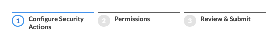
- In step 1, Configure Security Actions, enter information for the following fields.
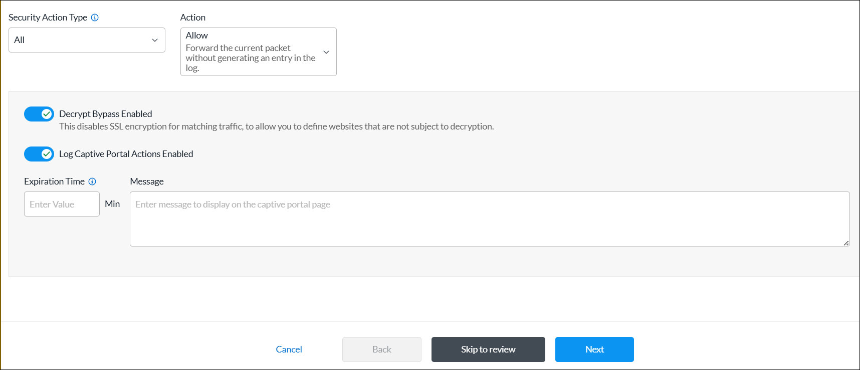
Field Description Security Action Type Select a security action type:
- All
- CASB
- Decryption
- DNS
- Intrusion Prevention System (IPS)
- IP Filtering
- URL Filtering (URLF)
Action Select an action:
- Allow—Forward the current packet without generating an entry in the log.
- Drop Packet—Browser waits for a response from the server and then drops the packets.
- Drop Sessions—Browser waits for a response from the server and then drops the session.
- Reset Client—TCP Reset packet is sent to the client and the browser displays an error message indicating that the connection has been reset.
- Reset Client and Server—TCP Reset packet is sent to the server. The browser waits for a response from the server and then drops the session.
- Block—Present an alert page to the user and block the user from continuing, in case of HTTP/HTTPS.
- Inform—Browser presents an information page that allows the user to continue with the operation by clicking OK.
- Ask—Browser presents an information page that allows the user to either cancel the operation by clicking Cancel, or continue with the operation by clicking OK.
- Justify—Browser presents an information page that allows the user to either cancel the operation by clicking Cancel, or continue with the operation after entering a justification message and clicking OK.
- Override—Browser prompts the user to enter a PIN (4 to 6 digits).
- Custom Redirection—Browser redirects the user to the URL configured in the Redirection URL field.
- Sinkhole—A DNS sinkhole spoofs DNS servers to prevent the resolution of the host names associated with URLs. And returns a false IP address to the URL, blocking a DNS sinkhole.
Decrypt Bypass (For all security types except CASB.) Click the toggle to disable SSL encryption for matching traffic, to allow you to define web sites that are not subject to decryption.
Default: Enabled
Log Captive Portal Actions (For all security types except CASB.) Click the toggle to enable the logging of captive portal actions.
Default: Disabled
Expiration Time (For security types IP Reputation and URL Filtering.) Enter how often to redirect a user to the URL, in minutes. Message (For security types IP Reputation and URL Filtering.) Enter a message to display on the captive portal page. - Click Next to go to step 2, Permissions.
- The permission for each role is selected by default, and you can update it. To change permissions for a role, select or deselect the Create, Read, Update, and Delete fields for the role.
- Click Next to go to step 3, Review and Submit.
- In the General section, enter a name for the reusable object. You can also enter a description and tags. A tag is an alphanumeric descriptor, with no white spaces or special characters, that you can use to search the objects.
- Click Submit.
Services
Security policies can reference service objects, which define match criteria based on protocol name and number, and on source and destination port number. Versa Networks provides default predefined services and object definitions, and also provides periodic updates to the default services and objects.
You can also create custom service objects. One reason to do this might be if a well-known service runs on a non-standard port or if the predefined services are missing the desired port and protocol combination. Another reason might be to limit the number of ports that an application can use. For example, you could limit FTP to use only port 21 instead of ports 20 and 21.
The custom service objects that you define for a tenant can be used only by that tenant, and they are not visible to any other tenants.
You can define service objects using one of the following methods:
- When you configure a policy rule that references service objects, you can click + Create New to create new service objects inline.
- Configure the service object from the main menu. Then, when you configure a policy rule that references a service object, you can select that service.
To configure service objects inline when you are configuring a policy rule, continue to Add a Service Object, below.
To configure a service object from the main menu:
- In Tenant view, select Configure > SD-WAN > Reusable Objects > Services.
- If you have not yet configured a service object, click Add Service.
- If you have configured one or more services, the following screen displays. Click the + Add icon.
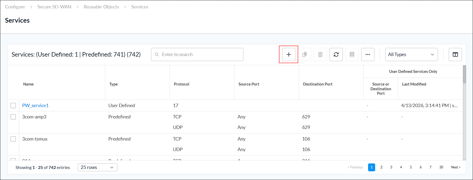
- Continue to Add a Service Object, below.
Add a Service Object
Complete the following workflow to create a custom service object.

- In step 1, Protocol & Port, enter information for the following fields.
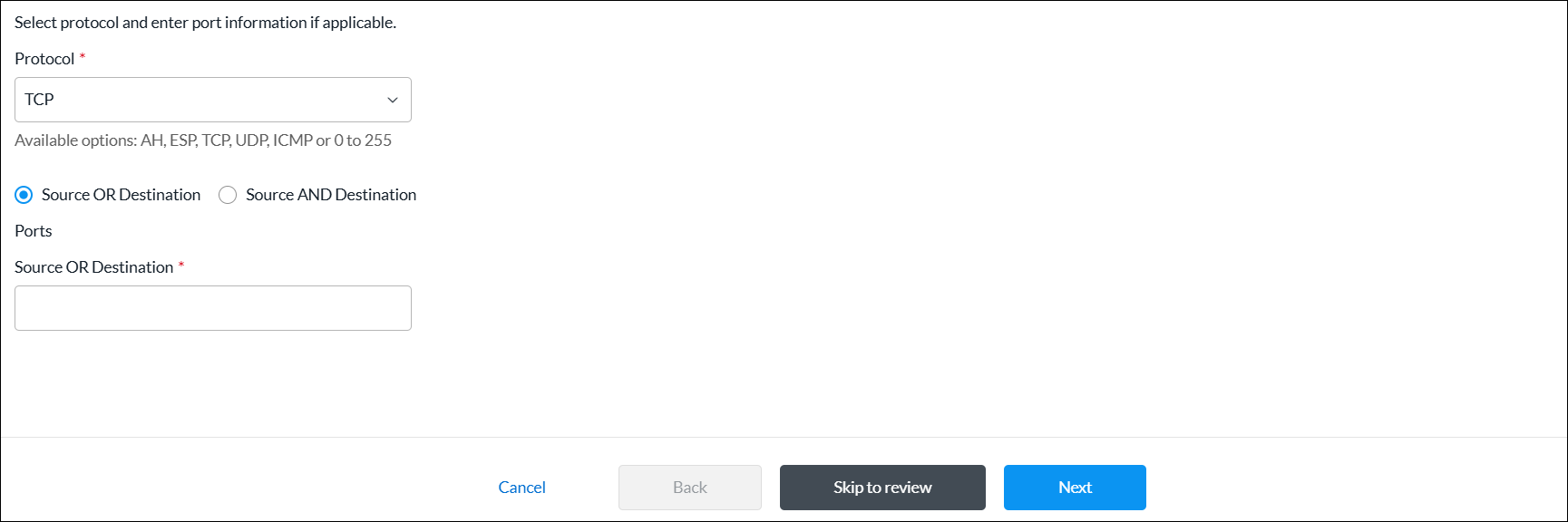
Field Description Protocol (Required) Select a protocol. The options are:
- AH (Authentication Header)
- ESP (Encapsulating Security Payload)
- ICMP (Internet Control Message Protocol)
- TCP
- TCP_OR_UDP
- 0 to 255
Source OR Destination Click to enter the source or destination ports. - Source OR Destination (Required)
Enter the source or destination port for the protocol. For multiple entries, use comma-separated single port values or a range of port values separated by a hyphen, for example, 1-100, 2-200, 3. Range: 0 through 65535
Default: None
Source AND Destination Click to enter the source and destination ports. - Source
(For TCP, UDP, or TCP_OR_UDP protocols only.) Enter the source port for the protocol. For multiple entries, use comma-separated single port values or a range of port values separated by a hyphen, for example, 1-100, 2-200, 3.
Range: 0 through 65535
Default: None
- Destination
(For TCP, UDP, or TCP_OR_UDP protocols only.) Enter the destination port for the protocol. For multiple entries, use comma-separated single port values or a range of port values separated by a hyphen, for example, 1-100,2-200,3.
Range: 0 through 65535
Default: None
- Click Next to go to step 2, Permissions.
- The permission for each role is selected by default, and you can update it. To change permissions for a role, select or deselect the Create, Read, Update, and Delete fields for the role.
- Click Next to go to step 3, Review and Submit.
- In the General section, enter a name for the reusable object. You can also enter a description and tags. A tag is an alphanumeric descriptor, with no white spaces or special characters, that you can use to search the objects.
- Click Submit.
Service Groups
Service groups combine multiple services into a single service group to simplify network configurations, particularly in firewalls and other security devices. Service groups are used when setting up SD-WAN policy rules. You can create custom service groups in addition to the predefined service groups provided by Versa Networks.
You can create custom service groups using one of the following methods:
- When you configure a policy rule that references custom services, you can click + Create New to add new custom service group inline.
- Create the custom service group from the main menu. Then, when you configure a policy rule that references services, you can select that service group.
To add custom service groups inline when you are configuring a policy rule, continue to Add a Service Group, below.
To configure custom service groups:
- In Tenant view, select Configure > SD-WAN > Reusable Objects > Service Groups.
- If you have not yet configured a custom service group, click Add Service Group.
- If you have configured one or more custom service groups, the following screen displays. Click the + Add icon.

- Continue to Add a Service Group, below.
Add a Service Group
Complete the following workflow to create a custom service group.

- In step 1, Services, select one or more user-defined and predefined services to add to the group.
- To filter the services in the services list, select any of the following from the All Types drop-down list:
- All Types— Displays user-defined and predefined services in the list. This is the default.
- User-Defined—Select to display user-defined services in the list.
- Predefined—Select to display predefined services in the list.
- To add a service object, click the + Add icon. See Add a Service Object section above.

- To filter the services in the services list, select any of the following from the All Types drop-down list:
- Click Next to go to step 2, Permissions.
- The permission for each role is selected by default, and you can update it. To change permissions for a role, select or deselect the Create, Read, Update, and Delete fields for the role.
- Click Next to go to step 3, Review and Submit.
- In the General section, enter a name for the reusable object. You can also enter a description and tags. A tag is an alphanumeric descriptor, with no white spaces or special characters, that you can use to search the objects.
- Click Submit.
URL Categories
You can create custom URL category objects to use in NGFW and SD-WAN policy rules. You can also specify custom URL categories in the category-based action rules and reputation-based action rules of a URL-filtering profile. The URL category object defines information about the URLs to match using a string match or a pattern match.
You configure URL categories on a per-tenant basis. For a given tenant, each URL category must have a unique name.
You can create URL categories using one of the following methods:
- When you configure a policy rule that references URL categories, you can click + Create New to add new URL categories inline.
- Configure the URL categories from the main menu. Then, when you configure a policy rule that references a URL category, you can select that URL category.
To add URL categories inline when you are configuring a policy rule, continue to Add a URL Category, below.
To add URL categories from the main menu:
- In Tenant view, select Configure > SD-WAN > Reusable Objects > URL Categories.
- If you have not yet configured a custom URL category, click Add URL Category.
- If you have configured one or more custom URL categories, the following screen displays. Click + Add.

- Continue to Add a URL Category, below.
Add a URL Category
Complete the following workflow to create a custom service object.

- In step 1, Settings, enter information for the following fields.
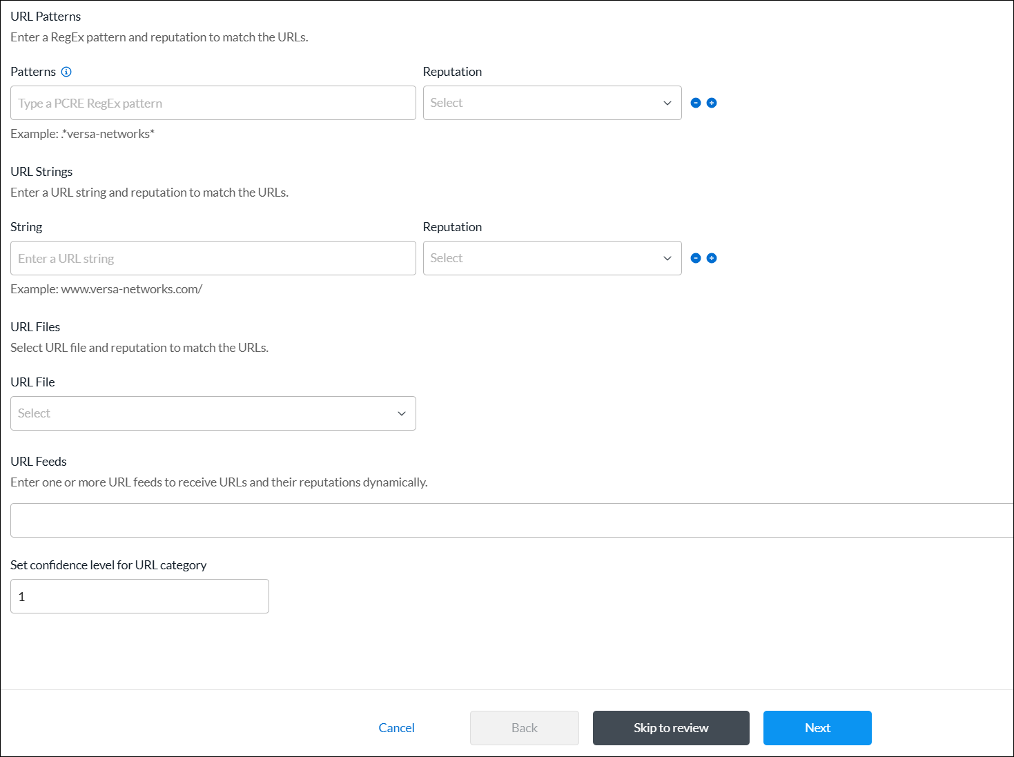
Field Description URL Patterns (Group of Fields) - Patterns
Enter a URL pattern to match and group the URLs. You can include regex patterns. For example, you can use the pattern www.versa-networks.com, or you can use a wildcard such as *.versa-networks.
To include a backslash character (\) in the regex pattern, you must escape it by preceding it with a backslash.
- Reputation
Select a predefined reputation, and then assign it to the URL match pattern. URL Strings (Group of Fields) - String
Enter a URL string to match the URL, for example, www.versa-networks.com. - Reputation
Select a predefined reputation, and then assign it to the URL string. URL Files Select a URL file. To add a new URL file, click + Create New.
- In the Upload File popup window, click Browse, select a URL file to upload, and then click Submit. The file must be in CSV format.
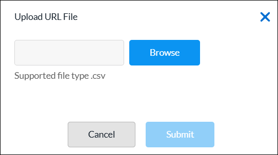
URL Feeds Enter one or more URL feeds to receive URLs and their reputations dynamically. Set confidence level for URL category Enter a confidence level number for the URL category.
Range: 1 through 100
- Click Next to go to step 2, Permissions.
- The permission for each role is selected by default, and you can update it. To change permissions for a role, select or deselect the Create, Read, Update, and Delete fields for the role.
- Click Next to go to step 3, Review and Submit.
- In the General section, enter a name for the reusable object. You can also enter a description and tags. A tag is an alphanumeric descriptor, with no white spaces or special characters, that you can use to search the objects.
- Click Submit.
Zones
For network interfaces that have identical security requirements, you can group them into a single security zone. You can then associate a security policy to the zone to apply the same protections to all interfaces in that zone. You can configure a zone on a per-tenant basis. For a given tenant, each zone must have a unique name.
To configure zones inline when you are configuring a policy rule, continue to Configure Zones, below.
To configure zones from the main menu:
- In Tenant view, select Configure > SD-WAN > Reusable Objects > Zones.
- If you have not yet configured a zone, click Add Zone.
- If you have configured one or more zones, the following screen displays. Click the + Add icon.
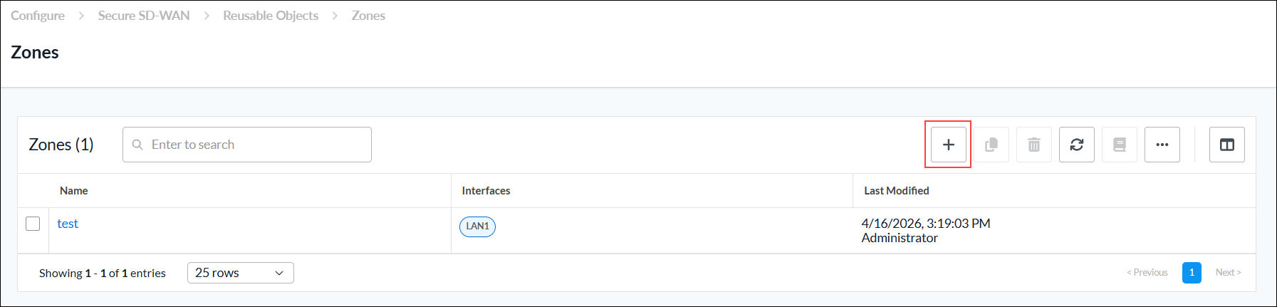
- Continue to Configure Zones, below.
Configure Zones
Complete the following workflow to configure a zone.

- In step 1, Zones, select one or more interfaces to add to the zone that share the same security requirements.

- Click Next to go to step 2, Permissions.
- The permission for each role is selected by default, and you can update it. To change permissions for a role, select or deselect the Create, Read, Update, and Delete fields for the role.
- Click Next to go to step 3, Review and Submit.
- In the General section, enter a name for the reusable object. You can also enter a description and tags. A tag is an alphanumeric descriptor, with no white spaces or special characters, that you can use to search the objects.
- Click Submit.
Supported Software Information
Releases 13.1.1 and later support all content described in this article.