Configure the Versa Advanced Logging Service
![]() For supported software information, click here.
For supported software information, click here.
Security users require detailed logging so that they can gather information for forensics, troubleshooting, and regulations. This amount of logging information can generate large or unpredictable volumes of data. The following are some of the challenges to processing this data using on-premises equipment:
- Resource-constrained customer environment—Requires a large number of instances within an Analytics clusters with dedicated compute or memory and fast disk I/O resources. Customers must be able to monitor the load on instances and dynamically grow the cluster.
- Specialized big-data–based system maintenance—Requires experienced network operations center (NOC) teams who are familiar with the technology to manage nodes and other components.This maintenance also requires periodic pruning of old data, and monitoring for load, response times, and failures.
- Rapid upgrades—Ability to run latest software versions without dependency on nodes such as Versa Director nodes or Versa Operating System™ (VOS™) devices to receive faster access to bug fixes, vulnerability fixes, and scalability or performance enhancements.
To support the gathering and analysis of large amounts of logging information, you can use the advanced logging service (ALS), which is a Versa-managed, cloud-hosted service that provides the following:
- On-demand scaling of logs without maintaining large clusters locally
- Single pane view available from an on-premises cluster
- Secure transport of logs
- Predictable pricing based on storage requirements
The following figure shows an example of a high-level view of the Versa ALS. This topology has two groups of Analytics clusters, one that is on-premises and a second that is hosted in the cloud by the Versa Networks NOC. The orange line shows that Branch 1 sends its logs, except for the high-volume search logs, to the on-premises Analytics cluster. These logs are accessible in the normal way, by selecting the Analytics tab on the active Director node, which connects to the Analytics application on the cluster to interact with the cluster. The red line shows that Branch 1 sends high-volume search logs to the ALS cluster in the cloud. The yellow line shows that the high-volume search log data can be accessed from the active Director node using the on-premises Analytics cluster as an intermediary. All logs are transferred from Branch 1 to either the on-premises or cloud-hosted nodes using a Versa Controller node as an intermediary.

The numbered items in the figure highlight how you configure the on-premises VOS client devices to use ALS:
- On Branch 1, you configure the default log export functionality (LEF) profile that is used to send logs to the on-premises (local) cluster through the SD-WAN Controller node,
- On Branch 1, you configure a second LEF profile that is used to send high-volume search logs to the ALS cluster, also through the SD-WAN Controller node.
- The Analytics application on the on-premises (local) cluster receives data from local analytics and search nodes for default dashboards, reports, and log screens.
- The Analytics application on the on-premises (local) cluster receives data from search nodes of the logging service cluster for logs stored in the ALS cluster.
Configure Clients To Use the ALS
To enable the ALS, you configure a Controller node, the VOS branch device, and a connector between the local Analytics cluster and the cloud-hosted ALS cluster. The following figure illustrates a functional view of the client configuration components.
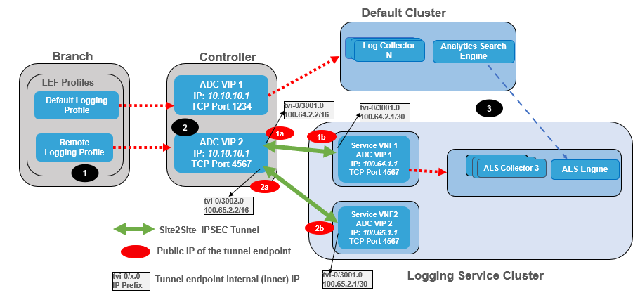
The figure shows the following configuration steps:
- You configure the branch with new a LEF profile that steers the flow logs to the ADC service on the Controller node.
- You configure the Controller node with both IPsec tunnels to establish a secure connection to the logging service virtualized network functions (VNFs) and an ADC service to forward logs; here the ADC service is named VIP2 and uses IP address 10.10.10.1, port 4567. This ADC service uses a load-balancing algorithm to distribute logs to ADC services pre-configured on the VNFs in the logging service cluster.
- You configure the Analytics application to set up connectors to the ALS cluster so that the local Analytics cluster can retrieve data using APIs.
Configure the Controller Node
The Versa ALS cluster is preconfigured with VNFs, each of which is running an ADC service that is configured to receive LEF connections from on-premises Controller nodes. To securely send logs to the VNFs over a public network, you configure IPsec tunnels from an on-premises SD-WAN Controller node to each VNF in the ALS cluster. The Versa Networks managed services team provides you with the information required to configure tunnels to the VNFs. The VNF ADCs accept incoming LEF connections at preset ports.
Also on the on-premises Controller node, you configure an ADC service to forward LEF connections to the preset ports for the VNF ADCs. The VNF ADC distributes incoming connections to ALS collectors. The ALS collectors receive logs over the LEF connections and forward the logs to the ALS engine.
To configure the on-premises Controller node, you issue a series of commands from the node's CLI. The following table describes the command parameters that you use to set up IPsec tunnels and the ADC server pools on the Controller node. Note that if you have purchased the ALS, the Versa Networks managed services team provides the values of the fields for which the owner is marked as Versa Networks. To configure the IPsec tunnels, you must share the public IP addresses of your organization's Controller nodes with the Versa Networks managed services team.
| Parameter | Description | Owner | Value |
|---|---|---|---|
|
Controller1-Public-IP-Address |
Public IP address of Controller1 from which an IPsec tunnel is initiated |
Customer |
Provided by customer |
|
Controller2-Public-IP-Address |
Public IP address of Controller2 from which an IPsec tunnel is initiated |
Customer |
Provided by customer |
|
FQDN-Name |
Name of the service VNF |
Versa Networks |
logging-service.com |
|
ServiceVNF1-ADC-Address |
Service VNF1 ADC VIP IP address configured on the on-premises Controller node’s ADC server list |
Versa Networks |
100.64.1.1 |
|
ServiceVNF2-ADC-Address |
Service VNF2 ADC VIP IP address configured on the on-premises Controller node’s ADC server list |
Versa Networks |
100.65.1.1 |
|
Service-VNF1-Public-IP-Address |
Public IP address of the service VNF1 |
Versa Networks |
Provided by Versa Networks |
|
Service-VNF2-Public-IP-Address |
Public IP address of the service VNF2 |
Versa Networks |
Provided by Versa Networks |
|
TVI-IP-Address1 |
Local tunnel IP address for IPsec tunnel towards service VNF1 |
Versa Networks |
Provided by Versa Networks |
|
TVI-IP-Address2 |
Local tunnel IP Address for IPsec tunnel towards service VNF2. |
Versa Networks |
Provided by Versa Networks |
To configure the Controller node:
- To configure interfaces and routes, issue the following CLI commands on the Controller node:
set interfaces tvi-0/3001 unit 0 family inet address TVI-IP-Address1
set interfaces tvi-0/3002 unit 0 family inet address TVI-IP-Address2
set routing-instances Internet-1-Transport-VR interfaces [ tvi-0/3001.0 tvi-0/3002.0 ]
set routing-instances Internet-1-Transport-VR routing-options static route ServiceVNF1-ADC-Addr/32 0.0.0.0 tvi-0/3001.0
set routing-instances Internet-1-Transport-VR routing-options static route ServiceVNF2-ADC-Addr/32 0.0.0.0 tvi-0/3002.0
- To configure an organization, issue the following CLI commands:
set orgs org Provider-Organization traffic-identification using tvi-0/3001.0
set orgs org Provider-Organization traffic-identification using tvi-0/3002.0
- To configure a site-to-site IPsec tunnel, issue the following CLI commands:
set orgs org-services Provider-Organization ipsec vpn-profile Ctrl-To-Log-SVNF1 vpn-type site-to-site
set orgs org-services Provider-Organization ipsec vpn-profile Ctrl-To-Log-SVNF1 local-auth-info
set orgs org-services Provider-Organization ipsec vpn-profile Ctrl-To-Log-SVNF1 local-auth-info auth-type psk
set orgs org-services Provider-Organization ipsec vpn-profile Ctrl-To-Log-SVNF1 local-auth-info id-type ip
set orgs org-services Provider-Organization ipsec vpn-profile Ctrl-To-Log-SVNF1 local-auth-info key password123
set orgs org-services Provider-Organization ipsec vpn-profile Ctrl-To-Log-SVNF1 local-auth-info id-string local-public-IP-address
set orgs org-services Provider-Organization ipsec vpn-profile Ctrl-To-Log-SVNF1 local
set orgs org-services Provider-Organization ipsec vpn-profile Ctrl-To-Log-SVNF1 local interface-name local-WAN-VNI-interface>
set orgs org-services Provider-Organization ipsec vpn-profile Ctrl-To-Log-SVNF1 routing-instance Internet-1-transport-VR
set orgs org-services Provider-Organization ipsec vpn-profile Ctrl-To-Log-SVNF1 tunnel-routing-instance Internet-1-transport-VR
set orgs org-services Provider-Organization ipsec vpn-profile Ctrl-To-Log-SVNF1 ipsec fragmentation pre-fragmentation
set orgs org-services Provider-Organization ipsec vpn-profile Ctrl-To-Log-SVNF1 ipsec force-nat-t disable
set orgs org-services Provider-Organization ipsec vpn-profile Ctrl-To-Log-SVNF1 ipsec transform esp-aes256-sha256
set orgs org-services Provider-Organization ipsec vpn-profile Ctrl-To-Log-SVNF1 ipsec mode tunnel
set orgs org-services Provider-Organization ipsec vpn-profile Ctrl-To-Log-SVNF1 ipsec pfs-group mod2
set orgs org-services Provider-Organization ipsec vpn-profile Ctrl-To-Log-SVNF1 ipsec anti-replay enable
set orgs org-services Provider-Organization ipsec vpn-profile Ctrl-To-Log-SVNF1 ipsec life duration 800
set orgs org-services Provider-Organization ipsec vpn-profile Ctrl-To-Log-SVNF1 ipsec hello-interval send-interval 10
set orgs org-services Provider-Organization ipsec vpn-profile Ctrl-To-Log-SVNF1 ike version v2
set orgs org-services Provider-Organization ipsec vpn-profile Ctrl-To-Log-SVNF1 ike group mod2
set orgs org-services Provider-Organization ipsec vpn-profile Ctrl-To-Log-SVNF1 ike transform aes256-sha256
set orgs org-services Provider-Organization ipsec vpn-profile Ctrl-To-Log-SVNF1 ike lifetime 900
set orgs org-services Provider-Organization ipsec vpn-profile Ctrl-To-Log-SVNF1 ike dpd-timeout 30
set orgs org-services Provider-Organization ipsec vpn-profile Ctrl-To-Log-SVNF1 peer-auth-info
set orgs org-services Provider-Organization ipsec vpn-profile Ctrl-To-Log-SVNF1 peer-auth-info auth-type psk
set orgs org-services Provider-Organization ipsec vpn-profile Ctrl-To-Log-SVNF1 peer-auth-info id-type fqdn
set orgs org-services Provider-Organization ipsec vpn-profile Ctrl-To-Log-SVNF1 peer-auth-info key password123
set orgs org-services Provider-Organization ipsec vpn-profile Ctrl-To-Log-SVNF1 peer-auth-info id-string FQDN-Name
set orgs org-services Provider-Organization ipsec vpn-profile Ctrl-To-Log-SVNF1 peer
set orgs org-services Provider-Organization ipsec vpn-profile Ctrl-To-Log-SVNF1 peer address [ Service-VNF1-public-IP-address ]
set orgs org-services Provider-Organization ipsec vpn-profile Ctrl-To-Log-SVNF1 tunnel-interface tvi-0/3001.0

set orgs org-services Provider-Organization ipsec vpn-profile Ctrl-To-Log-SVNF2 vpn-type site-to-site
set orgs org-services Provider-Organization ipsec vpn-profile Ctrl-To-Log-SVNF2 local-auth-info
set orgs org-services Provider-Organization ipsec vpn-profile Ctrl-To-Log-SVNF2 local-auth-info auth-type psk
set orgs org-services Provider-Organization ipsec vpn-profile Ctrl-To-Log-SVNF2 local-auth-info id-type ip
set orgs org-services Provider-Organization ipsec vpn-profile Ctrl-To-Log-SVNF2 local-auth-info key password123
set orgs org-services Provider-Organization ipsec vpn-profile Ctrl-To-Log-SVNF2 local-auth-info id-string Local-Public-IP-address
set orgs org-services Provider-Organization ipsec vpn-profile Ctrl-To-Log-SVNF2 local
set orgs org-services Provider-Organization ipsec vpn-profile Ctrl-To-Log-SVNF2 local interface-name Local-WAN-VNI-Interface
set orgs org-services Provider-Organization ipsec vpn-profile Ctrl-To-Log-SVNF2 routing-instance Internet-1-Transport-VR
set orgs org-services Provider-Organization ipsec vpn-profile Ctrl-To-Log-SVNF2 tunnel-routing-instance Internet-1-Transport-VR
set orgs org-services Provider-Organization ipsec vpn-profile Ctrl-To-Log-SVNF2 ipsec fragmentation pre-fragmentation
set orgs org-services Provider-Organization ipsec vpn-profile Ctrl-To-Log-SVNF2 ipsec force-nat-t disable
set orgs org-services Provider-Organization ipsec vpn-profile Ctrl-To-Log-SVNF2 ipsec transform esp-aes256-sha256
set orgs org-services Provider-Organization ipsec vpn-profile Ctrl-To-Log-SVNF2 ipsec mode tunnel
set orgs org-services Provider-Organization ipsec vpn-profile Ctrl-To-Log-SVNF2 ipsec pfs-group mod2
set orgs org-services Provider-Organization ipsec vpn-profile Ctrl-To-Log-SVNF2 ipsec anti-replay enable
set orgs org-services Provider-Organization ipsec vpn-profile Ctrl-To-Log-SVNF2 ipsec life duration 800
set orgs org-services Provider-Organization ipsec vpn-profile Ctrl-To-Log-SVNF2 ipsec hello-interval send-interval 10
set orgs org-services Provider-Organization ipsec vpn-profile Ctrl-To-Log-SVNF2 ike version v2
set orgs org-services Provider-Organization ipsec vpn-profile Ctrl-To-Log-SVNF2 ike group mod2
set orgs org-services Provider-Organization ipsec vpn-profile Ctrl-To-Log-SVNF2 ike transform aes256-sha256
set orgs org-services Provider-Organization ipsec vpn-profile Ctrl-To-Log-SVNF2 ike lifetime 900
set orgs org-services Provider-Organization ipsec vpn-profile Ctrl-To-Log-SVNF2 ike dpd-timeout 30
set orgs org-services Provider-Organization ipsec vpn-profile Ctrl-To-Log-SVNF2 peer-auth-info
set orgs org-services Provider-Organization ipsec vpn-profile Ctrl-To-Log-SVNF2 peer-auth-info auth-type psk
set orgs org-services Provider-Organization ipsec vpn-profile Ctrl-To-Log-SVNF2 peer-auth-info id-type fqdn
set orgs org-services Provider-Organization ipsec vpn-profile Ctrl-To-Log-SVNF2 peer-auth-info key password123
set orgs org-services Provider-Organization ipsec vpn-profile Ctrl-To-Log-SVNF2 peer-auth-info id-string FQDN-name
set orgs org-services Provider-Organization ipsec vpn-profile Ctrl-To-Log-SVNF2 peer
set orgs org-services Provider-Organization ipsec vpn-profile Ctrl-To-Log-SVNF2 peer address [ Service-VNF2-public-IP-address ]
set orgs org-services Provider-Organization ipsec vpn-profile Ctrl-To-Log-SVNF2 tunnel-interface tvi-0/3002.0
- To configure an ADC, issue the following CLI commands:
set orgs org-services Provider-Organization adc lb servers Log-SVNF1 type any
set orgs org-services Provider-Organization adc lb servers Log-SVNF1 ip-address ServiceVNF1-ADC-address
set orgs org-services Provider-Organization adc lb servers Log-SVNF1 port 4567
set orgs org-services Provider-Organization adc lb servers Log-SVNF1 state enabled
set orgs org-services Provider-Organization adc lb servers Log-SVNF1 routing-instance Internet-1-Transport-VR

set orgs org-services Provider-Organization adc lb servers Log-SVNF2 type any
set orgs org-services Provider-Organization adc lb servers Log-SVNF2 ip-address ServiceVNF2-ADC-Address
set orgs org-services Provider-Organization adc lb servers Log-SVNF2 port 4567
set orgs org-services Provider-Organization adc lb servers Log-SVNF2 state enabled
set orgs org-services Provider-Organization adc lb servers Log-SVNF2 routing-instance Internet-1-Transport-VR

set orgs org-services Provider-Organization adc lb server-pools Log-SVNF-Pool type any
set orgs org-services Provider-Organization adc lb server-pools Log-SVNF-Pool member Log-SVNF1
set orgs org-services Provider-Organization adc lb server-pools Log-SVNF-Pool member Log-SVNF2

set orgs org-services Provider-Organization adc lb virtual-services Log-VAN-VIP type any
set orgs org-services Provider-Organization adc lb virtual-services Log-VAN-VIP address ADC-VIP-IP-address
set orgs org-services Provider-Organization adc lb virtual-services Log-VAN-VIP port 4567
set orgs org-services Provider-Organization adc lb virtual-services Log-VAN-VIP default-pool Log-SVNF-Pool
set orgs org-services Provider-Organization adc lb virtual-services Log-VAN-VIP routing-instance Provider-Control-VR
Configure the VOS Device in a Branch
The ADC service you configured in the previous section on the on-premises Controller nodes listens for incoming TCP or UDP connections at its configured ADC service tuple (IP address, transport, and port number). On the branch VOS device, you create a LEF collector to send logs to the ADC service tuple. You can optionally place multiple collectors into a LEF collector group. Then, you associate either an individual LEF collector or a LEF collector group with an LEF profile. To use the LEF profile, you associate it with features and services. This configures the VOS device to forward logs for those features and services to the on-premises Controller node, which then forwards the logs to the ALS cluster.
On the VOS device, you do the following:
- Configure a LEF collector.
- Optionally, configure a LEF collector group.
- Configure a LEF profile.
- Associate the LEF profile with features and services. Note that the screen associating a LEF profile differs for each feature or service. For more information about associating LEF profiles for specific features and services, see Apply Log Export Functionality.
The configuration below is an example that assumes you have configured two ADC services, each on a separate on-premises Controller node, to forward LEF connections to the ALS cluster. The first ADC service listens at IP address 10.20.64.1 and TCP port 4567. The second ADC service listens at IP address 10.20.64.2 and TCP port 4567. On the VOS device, you configure two LEF collectors, named LS-Collector1 and LS-Collector2, one for each ADC service. You next configure a LEF collector group, named LS-Collector-Group, containing the two collectors, and a LEF profile, named LS-Logging-Profile, which contains the collector group. Finally, you associate the LS-Logging-Profile profile with a firewall security policy so that the VOS device sends firewall logs to the ALS cluster.
To configure the LEF collectors LS-Collector1 and LS-Collector2:
- In Director view:
- Select the Configuration tab in the top menu bar.
- Select Devices > Devices in the horizontal menu bar. To have the menu display tenant organizations, double-click the provider organization.
- Select an organization in the left menu bar. To have the menu display tenant organizations, double-click the provider organization.
- Select a branch in the main pane. The view changes to Appliance view.
- Select the Configuration tab in the top menu bar.
- Select Objects & Connectors > Connectors> Reporting > Logging Export Function in the left menu bar.
- Select an organization in the Organization field.
- Select the Collectors tab, and then click the
 Add icon. The Add Collector popup window displays. For more information, see Configure a Collector.

- Enter collector name LS-Collector1, and then enter IP address 10.20.64.1 and port number 4567, and transport protocol TCP corresponding to the ADC service you configured in the section Configure the Controller Node, above. Select the routing instance you used to configure the ADC service, Provider-Control-VR. Select a LEF template that uses type IPFIX, here Default-LEF-Template.
- Repeat Steps 5 and 6 to configure the second collector, LS-Collector2. The second collector forwards logs to an ADC service configured on a second Controller node, which provides redundancy in case the first Controller node fails.
- Click OK. The table in the main pane displays the two new LEF collectors, LS-Collector1 and LS-Collector2.

To create LEF collector group LS-Collector-Group, which contains the two LEF collectors:
- Select the Collector Groups tab, and then click the Add icon. The Add Collector Group popup window displays.
- In the Collectors table, click the
 Add icon, and then add the collectors you added above, LS-Collector1 and LS-Collector2, to the group.
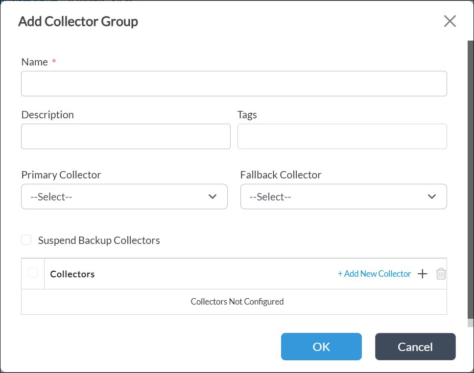
- For information about configuring the other fields, see Configure a Collector Group.
- Click OK.

To configure LEF profile LS-Logging-Profile and associate collector group LS-Collector-Group with the profile:
- Select the Profiles tab, and then click the
 Add icon. The Add Profile popup window displays.
 - In the Name field, enter a name for the LEF profile, here, LS-Logging-Profile.
- Click Collector Group, and then click the
 Add icon and select the collector group you added above, LS-Collector-Group.

- For information about configuring the other fields, see Configure a LEF Profile.
- Click OK.
To associate the LEF profile LS-Logging-Profile with a firewall security policy:
- In Director view:
- Select the Configuration tab in the top menu bar.
- Select Devices > Devices in the horizontal menu bar.
- Select an organization in the left menu bar. To have the menu display tenant organizations, double-click the provider organization.
- Select the device in the main pane. The view changes to Appliance view.
- Select the Configuration tab in the top menu bar.
- Select Services in the left menu bar.
- Select an organization in the Organization field.
- Select Next-Gen Firewall > Security> Policies in the left menu bar, and then select the Rules tab.
- Click the
 Add icon to define rules for the policy. The Add Rule popup window displays. For more information about configuring rules, see Configure Access Policy Rules.
 - Select the Enforce tab, and then select the Log tab.
- In the Events field, click an event (for example, End), and then select the LEF profile you configured above, here, LS-Logging-Profile.

- Click OK.
Configure a Connector
To establish communication between the Analytics cluster and the ALS cluster, you configure a new connector. Versa Networks provides you with the IP address or FQDN of the ALS cluster, and with the username and password for the on-premises cluster to use to connect to the ALS cluster. You then associate the connector to features and services so that the Analytics application can use ALS cluster data to populate dashboards, reports, and log screens for these features and services.
Before you configure the connectors to the ALS cluster, run the following script on the Analytics nodes to import the server certificate to connect the on-premises Analytics application to the ALS cluster. Use the ALS IP address or FQDN provided by Versa Networks and port 443 to import the certificate.
admin@Analytics$ sudo /opt/versa/scripts/van-scripts/van-cert-pull.sh -h
Usage: van-cert-pull.sh
Import certificate from a server to Analytics Truststore
Options:
  -h, --help      Show this help message and exit.
  --host   <IP/hostname/FQDN of the host whose certificate needs to be imported>
 --port <port>

admin@Analytics$ sudo /opt/versa/scripts/van-scripts/van-cert-pull.sh --host host-ip-address --port 443
Host => <host-ip>
depth=1 CN = als-analytics-01, O = versa-networks, OU = VersaAnalytics, C = US, ST = California, L = Santa Clara
DONE
Certificate was added to keystore
To configure a connector between an Analytics cluster and a node in an ALS cluster:
- In Director view, select the Analytics tab in the top menu bar.
- Select the Analytics node: (Note:You can select any node in the Analytics cluster to communicate with the cluster.)
- For Releases 22.1.1 and later, hover over the Analytics tab and then select an Analytics node.
- For Releases 21.2 and earlier, select an Analytics node in the horizontal menu bar.
- Select Administration > Configurations > Settings in the left menu bar.
- In the System Configuration main pane, select the Connectors tab.

- Click Add Connector. The Connector popup window displays.
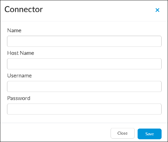
- Enter a connector name, hostname, username, and password.
- Click Save. This creates a connector in the on-premises cluster that automatically connects to the ALS cluster. The connector credentials are saved securely on the local cluster.
To configure the Analytics application to use the ALS cluster as its source of data for a feature or service:
- In Director view, select the Analytics tab in the top menu bar.
- Select an Analytics node in the horizontal menu bar. You can select any node in the Analytics cluster to communicate with the cluster.
- Select Administration > Configurations > Settings in the left menu bar, and then select the Data Configurations tab.
- Select Search Data Configurations.
- In the Connector column for the feature, select a connector to the ALS cluster. The following screenshot configures the Analytics application to use the ALS cluster as its source for firewall access log data, using connector AUS-ALS-01.

To display the log screen for the firewall access logs configured in the previous procedure:
- In Director view, select the Analytics tab in the top menu bar.
- Select an Analytics node in the horizontal menu bar. You can select any node in the Analytics cluster to communicate with the cluster.
- Select Home > Logs.
- Select Firewall in the left menu bar, and then select the Logs tab in the main pane to display the Firewall Logs table. The table is populated with data from the ALS cluster.

Recommended Log Types
The following table lists the flow (session) log types that are recommended for processing by the ALS service.
The first column in the table, VOS Feature or Service, describes the feature or service generating the logs. The description text matches what is displayed on the Analytics > Administration > Configurations > Settings > Data Configurations > Search Data Configurations screen, and you use this text when selecting a connector to the ALS cluster.
The second column, Syslog Identifier, lists the name of the syslog identifier, which is the label that VOS devices include in the syslog messages that they generate for the feature or service.
The third column, Path to Analytics Log Screen, lists the path to the Analytics screen that displays log information for the feature or service under Analytics > Logs.
The fourth column, LEF Profile Association, provides a link to the article that describes how to associate a LEF profile when you configure the feature or service that generates the logs. For more information about associating a LEF profile with a feature or service, see Apply Log Export Functionality.
| VOS Feature or Service | Syslog Identifier |
Path to Analytics Log Screen |
LEF Profile Association |
|---|---|---|---|
| Access Logs |
accessLog |
Logs > Firewall |
Configure Firewall Logging |
| Antivirus Logs | avLog | Logs > Threat Detection > Antivirus | Configure Antivirus (Malware) Logging |
| CGNAT Logs | cgnatLog | Logs > CGNAT | Configure CGNAT Logging |
| DHCP Logs | dhcpLog | Logs > DHCP | Configure DHCP Logging |
| DNS-Filtering Logs | dnsfLog | Logs > DNS > DNS Filtering | Configure DNS Filtering Logging |
| DoS Threat Logs | dosThreatLog | Logs > Threat Detection > DDoS | Configure DDoS Threats Logging |
| File-Filtering Logs | fileFilterLog | Logs > Threat Filtering > File Filtering | Configure File Filtering Logging |
| Traffic-Monitoring Logs | flowMonLog | Logs > Traffic Monitoring | Configure SD-WAN Traffic and Web Monitoring Logging |
| HTTP Traffic-Monitoring Logs | flowMonHttpLog | Logs > Web Monitoring | |
| IDP Logs | idpLog | Logs > Threat Detection > IDP | Configure IDP Threat Detection Vulnerability Logging |
| IP-Filtering Logs | ipfLog | Logs > Threat Filtering > IP Filtering | Configure IP Threats Logging |
| Packet Captures Logs | pcapLog | Logs > Packet Capture | Configure Packet Capture Logging |
| SSL Decryption Logs | sslSessionLog | Logs > SSL Decryption | Configure HTTP/HTTPS Proxy |
| URL-Filtering Logs | urlfLog | Logs > Threat Filtering > URL Filtering | Configure URL Filtering Threats Logging |
Supported Software Information
Releases 20.2 and later support all content described in this article.