Configure Dynamic Smart Ports
![]() For supported software information, click here.
For supported software information, click here.
A dynamic smart port is an 802.1X-enabled port on an SD-LAN switch that can automatically detect the type of device that is connected to it and, based on the device type, apply predefined configuration parameters to the port. The configuration parameters are predefined in dynamic port profiles that you create for different device types, such as IP phones, network printers, and wireless access points. This capability eliminates the need to manually configure the ports on each device.
This document describes how to configure dynamic smart ports. Dynamic smart ports are supported for use only with Cisco ISE as the RADIUS server, or with other RADIUS servers if they can be configured to send the Cisco-specific smart-port attribute-value (AV) pair.
Configuration Overview
When a client is attached to an SD-LAN 802.1X-enabled Ethernet port, it receives a dynamic profile name from the RADIUS server during the authentication process. The dynamic profile name maps to a preconfigured dynamic port interface (DPIF), and the DPIF configuration is applied to the port. When the device is disconnected, the original settings are restored.
Dynamic smart ports work in the following sequence:
- A user attaches a device to a dynamic smart port on an SD-LAN device.
- The SD-LAN device contacts a RADIUS server for port authentication.
- The RADIUS server returns a dynamic profile name.
- The SD-LAN device uses the dynamic profile name to identify the following:
- 802.1X authentication settings.
- DPIF configuration, which contains Ethernet port settings.
- The SD-LAN device switches the dynamic smart port to the DPIF settings. During the switchover, the SD-LAN device performs a 3-second interface flap in the following sequence: port down, 3 second pause, port up. The flap allows time for reauthenticating the port with the new 802.1X settings.
- If additional devices attach to the port after the switchover, the port continues to use the applied DPIF settings. The port reverts to base Ethernet settings when one of the following events occurs:
- The last device connected to the port disconnects.
- The port flaps.
To configure dynamic smart ports, you do the following:
- Configure a DPIF.
- Select an existing Ethernet interface and enable the dynamic interface option, which converts the interface to a dynamic smart port.
- Configure the SD-LAN device to access a RADIUS server.
- Configure the 802.1X settings to associate a DPIF with a dynamic profile name.
- Configure attribute-value (AV) pairs on the RADIUS server. Each pair contains a dynamic profile name that the RADIUS server returns to the SD-LAN device.
Configure DPIFs
A DPIF is a type of interface that contains the configuration parameters that you want to apply dynamically to a base Ethernet port.
To configure a DPIF:
- In Director view, select Administration in the horizontal menu bar, click Appliances in the left menu bar, and then select an appliance in the mane pain. The view changes to Appliance view.
- Select Configuration in the horizontal menu bar.
- Select Networking > Interfaces in the left menu bar. The following screen displays.

- Select the Dynamic Port tab in the horizontal submenu, then click the
 Add icon. The Add Dynamic Port Interface popup window displays.

- In the General tab, enter a unique DPIF number in the Interface Num field to identify the DPIF. The value range is 0 through 31.
- For devices requiring power from the port, configure the Priority and Power Mode settings:
- Click the PoE subtab, and then enter information for the following fields.

Field Description Priority Select the priority level. The options are: - Low
- Medium
- High
- Critical
Power Mode Select Enabled. - For the remaining fields in the General tab, enter the values as described in the Configure WAN Ethernet Interfaces or Configure LAN Ethernet Interfaces sections in Configure Interfaces.
Note: VNI and Enet interfaces have additional fields that are not required for dynamic port interfaces and do not appear in the Dynamic Port Interface screen shown above.
- Click the PoE subtab, and then enter information for the following fields.
- Click the Sub Interfaces tab in the Add Dynamic Port Interface popup window. The Add Subinterface screen displays.

- In the General tab, enter a unit number for the subinterface.
- Select the Bridge tab. The following screen displays.

- In the Interface Mode field, select Access or Trunk.
- In the VLAN ID List field, enter a single VLAN ID number, a range of numbers, or a series of comma-separated VLAN IDs.
- Click OK. The Add Dynamic Port Interface popup window displays.
- Click OK to save the DPIF configuration.
Enable the Dynamic Interface Option
To configure a dynamic smart port, you enable the Dynamic Interface option on a base Ethernet port. If you have not yet configured a base Ethernet port, see Configure LAN Ethernet Interfaces in Configure Interfaces for the complete procedure.
To enable the dynamic interface option on a base Ethernet port:
- In Director view, select Administration in the horizontal menu bar, click Appliances in the left menu bar, and then select an appliance in the mane pain. The view changes to Appliance view.
- Select Configuration in the horizontal menu bar.
- Select Networking > Interfaces in the left menu bar.
- Select the Enet tab in the main pane. The following screen displays any currently configured interfaces.

- Click the base Ethernet interface that you want to be a dynamic smart port in the main pane. The Edit ENet Interface popup window displays.
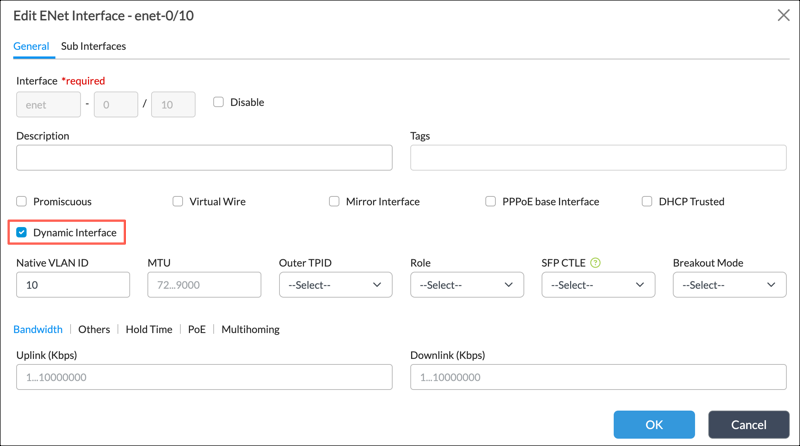
- Check the Dynamic Interface option.
- If you need the dynamic interface to supply power to PoE devices, select the PoE subtab. The following screen displays.

- Enter information for the following fields.
Field Description Priority Select the priority level. The options are: - Low
- Medium
- High
- Critical
Power Mode Select Enabled. - Click the Sub Interfaces tab.
- Click the Add icon. The Add Subinterface popup window displays.
- Select the Bridge tab.
- For the Interface Mode field, select Access or Trunk.
- For the VLAN ID List field, enter single VLAN ID numbers, a range of numbers, or a series of comma-separated VLAN IDs.
- Click OK.
Configure Access to the RADIUS Server
You configure access to RADIUS servers separately for each organization on an SD-LAN device.
To configure an organization to access the RADIUS server:
- In Director view, select the Administration tab in the top menu bar and then select an appliance in the main pane. The view changes to Appliance view.
- Select Configuration in the top menu bar.
- Select Others > Organization > Radius Servers in the left menu bar.

- Select an organization in the Organization drop-down list.

- Click + Add. The Add Radius Servers popup window displays.

- Enter information for the following fields.
Field Description Name (Required) Enter a name for the RADIUS server.
Description Enter a text description for the RADIUS server. IP Address (Required)
Enter the IP address of the RADIUS server. Port (Required) Enter the port number to use on the RADIUS server. Routing Instance Enter the routing instance to use to reach the RADIUS server. Shared Secret (Required) Enter the RADIUS shared secret (password) string. - Click OK.
- Select Others > Organization > Authentication Profile.

- Click + Add. The Add Authentication Profile popup window displays.

- Select the General tab. Enter information for the following fields.
Field Description Name Enter a name for the authentication profile. Type Select Radius. Description Enter a description for the authentication profile. Radius Server Select the RADIUS server you configured in Step 5. - You can use the remaining tabs to configure additional properties, if needed. For more information, see Configure an 802.1X Authentication Profile in Configure IEEE 802.1X Device Authentication.
- Click OK.
Configure 802.1X for DPIFs
You configure 802.1X for a DPIF by associating the DPIF with a dynamic port profile. The dynamic port profile, which resides on the RADIUS server, contains new 802.1X settings. When an SD-LAN device contacts a RADIUS server for port authentication, the RADIUS server returns this dynamic port profile. The 802.1X settings in the dynamic port profile overwrite the settings that were initially configured on the base Ethernet port.
The dynamic profile names may correspond to devices that require separate DPIF settings to be applied to the port. In this case, create separate DPIFs for these dynamic profile names, and then select the appropriate DPIF when configuring the 802.1X settings.
To add 802.1X settings for dynamic profile names:
- In Director view, select the Administration tab in the top menu bar and then select an appliance in the main pane. The view changes to Appliance view.
- Select Configuration in the top menu bar.
- Select an organization from the drop-down menu and then select the dot1x tab in the main pane.
- Click Edit. The following screen displays.

- Enter information for the following fields.
Field Description Authentication Profile
Select the name of the 802.1X authentication profile that you configured in Configure Access to the RADIUS Server. Interface Name Select a DPIF interface name.
Supplicant Select the supplicant type:
- Single - Authenticate only the first end device. All other end devices that connect to the port later are allowed access without any further authentication.
- Single Secure - Allow only one end device to connect to the port at a time. No other end device can connect until the first device logs out.
- Multiple - Allow multiple end devices to connect to the port. Each end device is authenticated individually. You can configure multiple mode only on bridge interfaces that are in trunk mode.
- Multiple Secure - Allows one end device to be connected in the voice VLAN and one in the authentication VLAN. Any additional devices are placed in the guest VLAN.
Enable Dynamic VLAN Check to enable dynamic assignment of VLANs based on the interface's 802.1X authentication. Enable Radius Dynamic VLAN Check to enable Radius dynamic VLAN, in which VLAN assignment is done based on the response from the RADIUS authentication server. Dynamic Profile Name Enter the name of the dynamic profile that you configured in the Authorization section on the RADIUS server.
Note: The dynamic profile name in the dot1x authorization profile must match the name of the authorization profile configured on the RADIUS server. For information about creating an authorization profile, see the documentation for the RADIUS server.
- For the remaining fields, enter values as described in Configure 802.1X Authentication Control in Configure IEEE 802.1X Device Authentication.
- Click the + Add icon to add an entry for the dynamic profile name to the table.
- Click OK.
Configure LLDP for DPIFs
You can provide LLDP functionality to a DPIF by selecting a DPIF interface when configuring an LLDP interface.
- Go to Configuration > Networking > LLDP. The following screen displays.

- Click the Edit icon. In the Edit LLDP screen, enter information for the following fields.

Field Description Advertisement Interval Enter the time interval for sending LLDP BPDUs.
Range: 5 through 32768 seconds
Default: 30 secondsHold Multiplier Enter a value for the LLDP hold multiplier. The hold multiplier is how long to cache information learned about neighbors before discarding it. If the device does not receive an LLDP packet from a connected device during the hold multiplier time, it removes the device from the neighbor information.
Range: 2 to 10
Default: 4LLDP Enable Click to enable LLDP.
- Click the Add icon. In the Create LLDP screen, enter information for the following fields.

Field Description Interface Select a DPIF interface from the list. - Disable
Click to disable the selected interface. - Disable Transmit
Click to disable transmitting from the selected interface. - Disable Receive
Click to disable receiving on the selected interface. Network Policy (Group of Fields) - Voice (Group of Fields)
- L2 Priority
Enter the L2 voice priority value.
Range: 0 through 8
Default: None
- DSCP-Priority
Enter the DSCP priority value.
Range: 0 through 63
Default: None
- Tagging
Select a voice tagging. The options are:
- Tagged
- Untagged
- Vlan-ID
Enter a voice VLAN ID.
Range: 0 through 4094
Default: None
- Voice Signaling (Group of Fields)
- L2 Priority
Enter the L2 voice signaling priority value.
Range: 0 through 8
Default: None
- DSCP-Priority
Enter the voice signaling DSCP priority value.
Range: 0 through 63
Default: None
- Tagging
Select a voice signaling tagging. The options are:
- Tagged
- Untagged
- Vlan-ID
Enter a voice signaling VLAN ID.
Range: 0 through 4094
Default: None
- Select the Location tab, then enter information for the following screens. For more information about the Civic Address options, see RFC 4776.

Field Description Location (Group of Fields) - Civic Address (Group of Fields)
- Additional
Enter additional Civic Address location information, if needed. - Additional Code Information
Enter additional code information, for example, 13203000003. - Block
Enter a block or neighborhood, if needed. - Branch Road Name
Enter the name or identifier of a road or street that intersects or is associated with a primary road, for example, Lane 7. - Building
Enter the name of a building or structure, for example, Public Library - City
Enter a city name. - City Division
Enter a city division, for example, borough, city district, ward.Enter - Country
Enter a country name. - County
Enter a county name. - Direction
Enter a directional indicator, for example, N, S, E, W. - Floor
Enter the floor number, for example, 7. - Landmark
Enter a nearby landmark, for example, Columbia University. - Language
Enter the language used for presenting the address information. - Name
Enter the name of the residence or office occupant, for example, Joe's Barbershop. - Number
Enter the street number of the residence, for example, 123. - Number Suffix
Enter a modifier to a street address, for example, A or 1/2. The suffix does not identify parts of a street address. - Place Type
Enter they type of place, for example, Office. - Postal Group Name
Enter a postal group name, if needed. - Primary Road Name
Enter the road or street name associated with the address. - Room
Enter the room number, for example, 450F. - Seat
Enter the seat number, for example, 181. - State
Enter the name of the state. - Street
Enter the street name. - Street Suffix
Enter a street suffix, for example, Avenue or Platz. - Trailing Street Prefix
Enter a trailing street prefix, such as SW or NE. - Unit
Enter a unit number, for example, Apartment 22 or Suite B. - Zip
Enter a postal Zip code, for example, 10027-1234. - Coordinate Based (Group of Fields)
- Altitude
Enter the altitude number. The value range is from –1000 through 10000. - Latitude
Enter the latitude number. The value range is from –180 through 180. - Longitude
Enter the longitude number. The value range is from –90 through 90. - Altitude-Type
Select the altitude type. The options are:
- Unknown
- Meters
- Floors
- Coordinate System
Select a coordinate system to use. The options are:
- Local
- NAD83
- Untagged
- ELIN
Enter the Emergency Location Identification Number (ELIN). The range is from 10 through 31.
- Click OK.
Configure AV Pairs on the RADIUS Server
On the Cisco RADIUS server, configure an authorization policy for devices attaching to the Ethernet port. In the policy, you add an AV pair of auto-smart-port=dynamic-profile-name to the Authorization Profile, and this value is returned to the SD-LAN device. If no AV pair is configured, then the SD-LAN device continues to use the settings for the base Ethernet port.
For example, to return a dynamic profile name of EAP_4000, configure the AV pair on the RADIUS server as follows:
cisco-av-pair = auto-smart-port=EAP_4000
Display the Current DPIF for an Ethernet Port
You can view the details of the smart port profile by issuing the show interfaces command from the CLI, as shown in the example below.
admin@device$ cli
admin@device> show interfaces detail enet-0/10

Interface: enet-0/10 Tenant 0
    Vlan-Id : n/a
    Inner-vlan-id : n/a
    Administrative status : up
    Operational status : up
    Protocols Down : n/a
    Interface index 1074
    Interface Role : external
    MAC address : ac:43:30:f8:f2:a0
    IP address : n/a
    Dynamic profile : EAP_4000
Supported Software Information
Releases 22.1.4 and later support all content described in this article.
Additional Information
Configure IEEE 802.1X Device Authentication
Configure Interfaces