Configure Miscellaneous Parameters
![]() For supported software information, click here.
For supported software information, click here.
In the Miscellaneous tab, you can configure the following miscellaneous parameters:
- Application-level gateway (ALG) profile—ALG is a communication protocol that connects Versa Operating SystemTM (VOSTM) devices with various services. For example, if you want to send files through FTP and to establish calls with VOS devices using SIP, you configure ALG for a branch.
- Captive portal port for SASE gateway—For the URLs whose access you want to control, you can redirect users to a captive portal webpage on which you can display standard or customized messages that provide information about the webpage. For these webpages, you can control access or block access completely. You can define clear-text (HTTP) and secure traffic ports (HTTPS) for captive portal. For Versa endpoint client, you must configure SASE gateway captive portal port as follows:
- HTTP—80
- HTTPS—443
- Loopback interface—You can configure loopback interfaces in routing instances that route large amount of data traffic and that require continuous connectivity. Loopback interfaces are always up. Loopback interfaces are primarily used for OSPF and BGP, because connectivity is never down. A routing instance or domain can have only one loopback interface. For a service provider with two routers, each router has a loopback interface and the routers maintain data connectivity over the loopback interface.
- Monitor—IP SLA monitoring continuously monitors and reports on traffic across the network. To configure and manage IP SLA monitoring, you create monitor objects and associate each object with IP address. You can also create a group of monitor objects. Note that you cannot configure IP SLA monitor objects and monitor groups for SASE gateway and multitenant gateway tenants from the Miscellaneous tab. To configure IP SLA monitor objects and monitor groups for SASE gateway and multitenant gateway tenants, see Configure Routing.
- Netflow Reporting Rules—You can configure and manage netflow reporting rules using match criteria such as protocol, address, hostname, application, URL, and DSCP, along with zone-based source and destination scope. Each rule supports logging and can optionally export flow records to a netflow collector for external monitoring and analytics.
- NTP server—You can configure the time settings on a VOS device in NTP mode.
- Override DF bit—The DF bit override functionality allows you to configure the setting of the DF bit when encapsulating tunnel mode IPsec traffic on a global or per-interface level. If you set the DF bit to clear, routers can fragment packets regardless of the original DF bit setting.
- Security pack (SPack) automatic update—A security pack (SPack) is a software bundle that contains predefined services and objects that you can use in firewall configurations to protect network devices from security threats. The predefined services include applications, URL categories, URL reputations, IP reputations, IDS and IPS signature definitions, firmware, and antivirus definitions. Versa Networks automatically updates the SPack on the device daily at 23:30 ;(11:30 p.m.) UTC or in the local timezone if the time is set by NTP. After this time, you can check the SPack Version column in the Inventory dashboard to see the latest version of the SPack installed. To check before the scheduled time, click the Refresh icon in the Monitoring dashboard screen and then check the SPack version in the Inventory dashboard.
- SNAT pool—You can manage all SNAT pools as objects on a device using SNAT pool. SNAT is a method of remapping one IP address space into another by modifying the network address information in a packet's IP header. SNAT is a type of NAT that translates the source IP address in the packet's header to an address that you configure. For SNAT to work, you can configure a source pool IP address that SNAT uses when translating source IP addresses. The SNAT pool is a range of IP addresses, and SNAT selects one of the source IP addresses from this pool. By using the egress network in SNAT pool, one of the IP address, that is allocated to the interface will be used as source address.
- SNMP—To configure SNMP, you must configure an SNMP profile. You can configure only one LAN or WAN with static IP address. To configure SNMP, you must first lock the device using the enable lock mode option in the honeycomb view in the Titan Portal home screen. The lock icon displays only if the device is deployed. A blue lock icon indicates that the device is unlocked, and a red lock icon indicates that the device is locked. After you publish the changes to Titan Portal, you must unlock the device. A private SASE gateway can modify this configuration only before the device is deployed and activated. To modify the configuration later, contact Versa Networks Customer Support. For more information, see Add an SNMP Profile.
- Configure a syslog server—Configure a reachable syslog IP server. A syslog server consolidates logs from multiple sources into a single location. Syslog messages contain information that identifies basic information about where, when, and why the log was sent, including the IP address, timestamp, and the actual log message. You configure a syslog server for each VOS device. You can add the port number at the end of the IP address in the format IP Address:PortNumber. The default port number is 514.
- Traffic shaper—Configure peak ingress rate in kilobits per second (kbps) and the maximum burst size, in bytes per second at the device level to control ingress traffic flow. Before you configure traffic shaper, you must also first lock the device using the enable lock mode option in the honeycomb view in the Titan Portal home screen. A private SASE gateway can modify this configuration only before the device is deployed and activated. To modify the configuration later, contact Versa Networks Customer Support.
- User Management—An enterprise administrator can add, edit, and delete custom VOS device users from Titan Portal. Custom users have access only to the CLI on VOS devices. An enterprise administrator can delete a custom user, but they cannot delete the default VOS users (admin and versa). An enterprise administrator can change the password for a custom user but cannot change the username. When you deactivate or undeploy a device, the password for the default users is reset to the factory default and all custom users are removed.
Default users can log in to the shell of a VOS device, which is a Bash shell, and they can access the CLI from the shell. When logging in to the CLI, the default user is placed at the CLI prompt. An MSP or a reseller with the Manage Service privilege level can read or write user management for custom VOS devices. - VNF manager—The VNF manager IP is the IP address assigned to the Versa VNF manager, which is used to manage and monitor Virtual Network Functions (VNFs) within the Versa SD-WAN environment.
- VRRP MAC Address Mode—Select a MAC address mode for Virtual Router Redundancy Protocol (VRRP) to provide flexibility in managing failover. Select virtual mode to ensure faster switchover, or physical mode to help comply with specific network policies.
To configure the miscellaneous parameters:
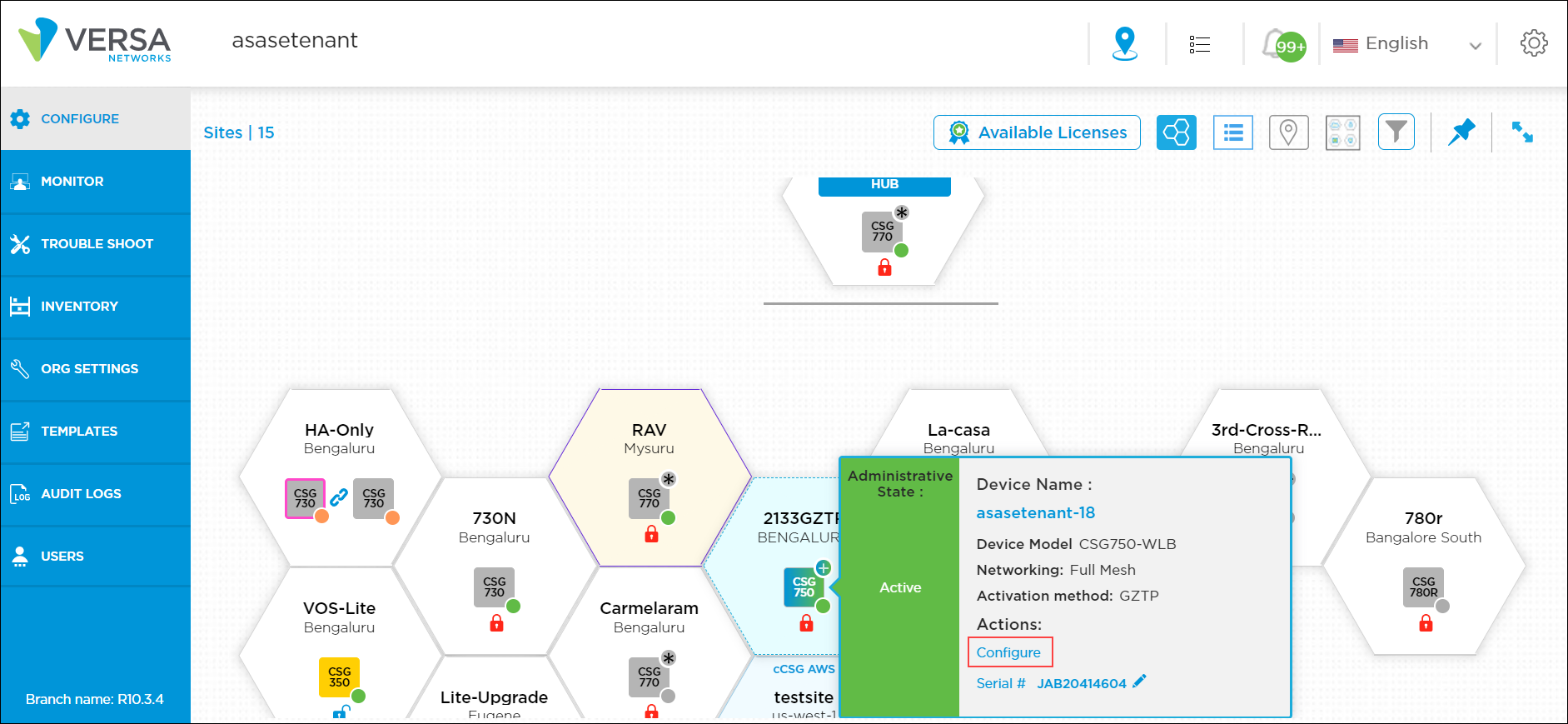
- Click Configure in the left menu bar to open the Configure dashboard.
- Hover over the device in the honeycomb, and click Configure to open the site information window.
- Click the Miscellaneous tab, and enter information for the following fields.

Field Description ALG Profile Select the ALG profile:
- FTP
- IKE-ESP
- PPTP
- SIP
- TFTP
Configure SNMP (Group of Fields) - Local Engine ID
Displays the administratively unique identifier for an SNMPv3 engine. The local engine ID is automatically generated and displayed if you do the following:
- In the SNMP profile, configure SNMP Version 3. See Add an SNMP Profile.
- Configure a LAN or WAN source interface for SNMP in the Source Interface field.
- In the Monitor dashboard, click Sync Configuration in the Device Options card for the device. See Verify Device Status.
- Source Interface
Select the LAN or WAN with static IP address to use to reach the SNMP server. - Source IP
Enter the IP address of the SNMP agent. Override DF Bit Select the override DF bit with IPsec tunnels to set the DF bit when encapsulating tunnel-mode IPsec traffic on a global or per-interface level. If the DF bit is set to clear, routers can fragment packets regardless of the original DF bit setting. VRRP MAC Address Mode Select the type of MAC address to use for VRRP:
- Physical—Uses the hardware MAC address of the active router as the VRRP MAC address. This may help comply with specific network policies.
- Virtual—Allows the active and backup routers to share the same MAC address, which ensures faster switchover. This is the default.
Configure NTP Server (Group of Fields) - Set Timezone
Select the timezone to set on the CPE device. - Set NTP Server (IP or Hostname)
Enter the IP address or hostname of the NTP server. - Set Source Network
Select the source network to use to reach the NTP server. Configure Syslog Server (Group of Fields) - Server IP
Enter the IP address of the syslog server. Add the port number at the end of the IP address in the format IP Address:PortNumber. The default port number is 514.
- Reachability Via
Select the reachability network between the device and the syslog server to send syslog messages. Captive Portal Port Number Click the Manage Captive Portal link. In the Captive Portal Port Number popup window, enter information for the following fields.

- Network Name (Required)—Click the Please Select drop-down list. In the Network Name popup window, click a WAN network.
- HTTP—Enter the HTTP port number to use to redirect captive portal pages over HTTP. The default port is 44990. For VSA, configure the SASE gateway captive portal port to 80.
- HTTPS—Enter the HTTPS port number to use to redirect captive portal pages over HTTPS. The default port is 44991. For VSA, configure the SASE gateway captive portal port to 443.
Loopback Interface Click the Loopback Interface link. In the Loopback Interface popup window, enter information for the following fields. To use this loopback interface, create a new security rule to allow traffic for this source IP address.

- Name (Required)—Enter a name for the loopback interface.
- IP Address (Required)—Enter an IPv4 address for the loopback interface.
- Routing Instance (Required)—Select a routing instance to use to access the loopback interface.
Click Add, and then click Continue.
SNAT Pool Click the Manage SNAT Pool link. In the Add SNAT popup window, enter information for the following fields.
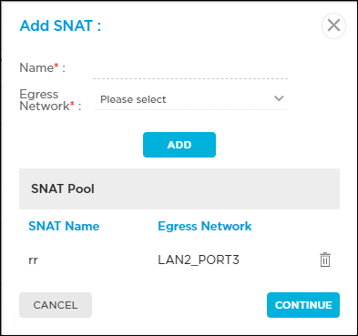
- Name (Required)—Enter a name for the SNAT pool.
- Egress Network (Required)— Select an egress network to use for cloud lookup requests.
Click Add, and then click Continue.
Monitor Click the Manage Monitor link to configure IP SLA monitor objects and monitor groups.
- To configure IP SLA monitor objects, select the Monitor tab, and then enter information for the following fields.

- Name (Required)—Enter a name for the IP SLA monitor object.
- Monitor Type (Required)—Select the type of packets to monitor on the IP address:
- DNS
- ICMP
- TCP
- Interval (Required)—Enter the time interval between monitor packets, in seconds.
Range: 1 through 60 seconds
Default: 3 seconds - Threshold (Required)—Enter the the number of monitor packet transmissions to be missed before setting the state of the node as down and withdrawing the static route.
Range: 1 through 60
Default: 5
- IP Address (Required)—Enter the IP address to monitor.
- Next Hop—Select the device to use as the next hop.
- Networks—Select the source network on which to send the probe packets.
- Source Interface—Select the source interface on which to send the probe packets.
- Click Add, and then click Continue.
- To configure IP SLA monitor groups, select the Monitor Group tab, and then enter information for the following fields. You can associate up to 8 monitors to a monitor group.

- Name (Required)—Enter a name for the IP SLA monitor group.
- Operations—Select the AND or OR operator:
- And—Monitor state is considered up, if all monitors in the monitor group are up.
- Or—Monitor state is considered up, if at least one of the monitors in the monitor group are up.
- List of Monitors—Select the monitor objects from the Available column to add to a monitor group. The selected objects will be moved to the Added column.
- Click Add, and then click Continue.
- To remove a monitor object, or all objects, from a monitor group:

- Click the
 Edit icon in the IP SLA monitor group.
 - In the Added column, click the
 icon to remove a single monitor object. Click Remove All to remove all objects in a monitor group.
- Click the
- Click the Edit icon to update a monitor group information.
- Click the
 Delete icon to delete the monitor group.
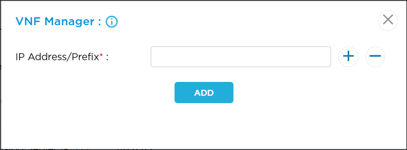
VNF Manager Click the VNF Manager link to enter the VNF manager IP address, and then click Add.
Netflow Reporting Rules Provides real-time flow reporting to supported netflow collectors. See Configure Netflow Reporting Rules. Security Pack (SPack) Auto Update Click the toggle button to disable automatic updating of the SPack. Before you can disable the SPack update, you must lock the device by selecting the enable lock mode option in the honeycomb view in the Titan Portal > Configure.
By default, automatic updating of the SPack is enabled.
For a private SASE gateway, you modify this configuration option only before deploying and activating the device.
Traffic Shaper (Group of Fields) - Peak Rate
Enter the peak ingress rate, in kilobits per second (kbps), for the device to control ingress traffic flow.
Range: 64 through 4294967295 kbps
Default: None
- Peak Burst Size
Enter the maximum burst size in bytes per second.
Range: 128 through 524288 bytes per second.
Default: None
User Management Click the User Management link. The Device User Management window displays.

- To add a user, enter information for the following fields.
- Username—Enter a name for the VOS device user.
Range: 2 through 31 characters - Role—Select the user role:
- Admin—Superuser with sudo privileges who can connect via SSH or to the CLI to the device on port 22 and port 2024. An admin user can modify any part of configuration. This is the default.
- Operator—Console user who can log in to only to the CLI and only using the physical or virtual console.
- Login—Select the login method:
- CLI
- Shell
Custom users with Admin and Operator roles have only CLI access.
- Password—Enter a password for the user. The password must be a minimum of 8 characters long.
- Confirm Password—Confirm the password.
- Username—Enter a name for the VOS device user.
- Click the Add button.
- To edit the user management information, click the Edit icon in the Action column.
- Click Continue.
- Click Publish.
Configure Netflow Reporting Rules
You can create and manage rules that control which traffic is exported as Netflow/IPFIX records.
To create a netflow reporting rule:
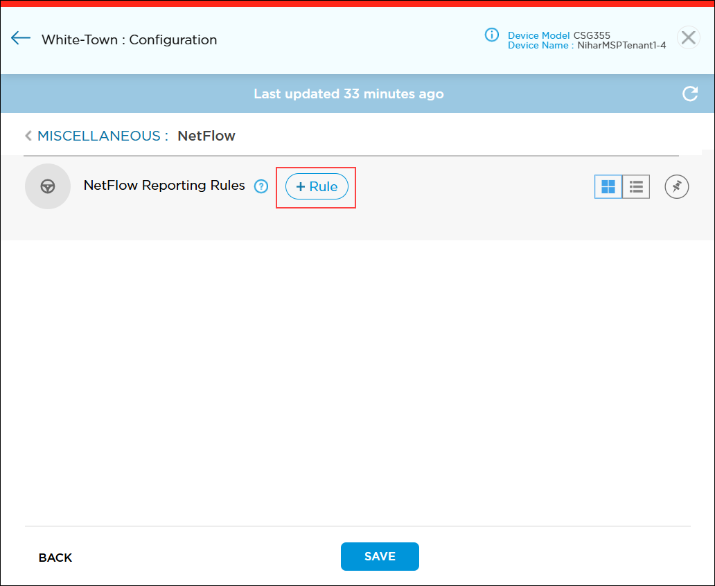
- In the Miscellaneous tab, go to Netflow Reporting Rules section, and then click the Rules link.

- In the Miscellaneous > Netflow screen, click the
 icon to add a new rule.
- In the Netflow Add window, enter information for the following fields.

Field Description Rule Name (Required) Enter a name for the rule, and then slide the toggle to enable the rule. Description Enter a text description for the rule. It can be a maximum of 63 characters. Match Criteria Select the Protocol, Address, Hostname, Application, URL, or DSCP tab to add information about that criteria type. For more information, see Apply Match Criteria for Netflow Reporting Rules, below.
Scope (Group of Fields) - Source Zone
Click the down arrow in the Please Select field. A popup window displays the configured interfaces and tunnels. Choose a source zone, and then click Continue. To create a tunnel, see Configure IPsec VPN Settings.

- Arrow
Choose the type of connection:
 One-way—Single arrow shows the traffic direction that checks match condition from source to destination in one direction.
 Two-way—Dual arrow means that the match condition is checked on both source to destination and destination to source.
- Destination Zone
Click the down arrow in the Please Select field. A popup window displays the configured interfaces and tunnels. Choose a destination zone, and then click Continue. To create a tunnel, see Configure IPsec VPN Settings.

Logging Configure log settings:
- None—Click to perform no logging.
- Default—Click to use default logging.
- Custom—Click to configure logging to a customer log server configured with IPFIX. Based on the rule match, the device may sent a large number of log messages.

-
Please Select—If you select Custom, click the down arrow to select a log profile.
-
Event—Select an option to log the data.
-
Start—Log data at the start of each session.
-
End—Log data at the end of each session.
-
Both—Log data at the start and end of each session.
-
Never—Never log data.
-
-
To create a new custom flow logs profile, click
 . For more information, see Add Custom Logs Profile.
Send to Netflow Collector Click to log data using a template that is compatible with netflow collectors.
Apply Match Criteria for Netflow Reporting Rules
You can apply the following match criteria types in a netflow reporting rule:
- Address
- Application
- DSCP
- Hostname
- Protocol
- URL
To specify the match criteria for a netflow reporting rule:
- In the Miscellaneous tab, go to Netflow Reporting Rules section, and then click the Rules link.
- In the Miscellaneous > Netflow screen, click the icon to add a new rule.
- In the Netflow Add window, go to Match Criteria section.

- To specify protocol criteria for a netflow reporting rule:
- Select the Protocol tab to display the protocol window.
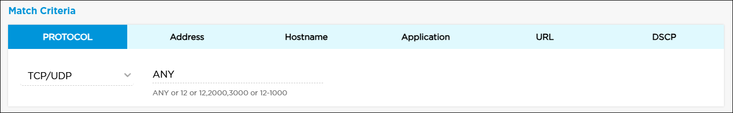
- In the Please Select field, select a protocol. Titan Portal automatically populates the next field with common port numbers.
- If needed, click the port number field and edit the port number range.
- Select the Protocol tab to display the protocol window.
- To specify address criteria for a netflow reporting rule:
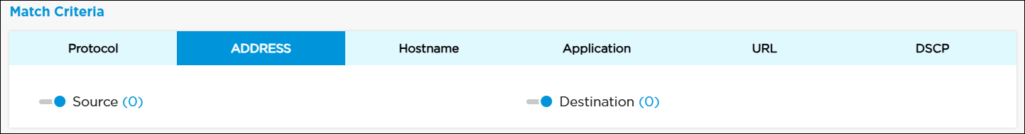
- Select the Address tab to display the address window.

- Click the toggle to enter the source or destination IP address.
- Click Source to enter a source IP address in CIDR format, and then click the
 icon. To remove an IP address from the list, click the
  icon.
icon.

- Click the Negate toggle to select any addresses except the configured addresses.
- Click the Import icon to enter multiple IP addresses separated by commas, and then click Update. Note that this overwrites any existing IP addresses.

- Click Continue
- Click Destination to enter a destination IP address in CIDR format, and then click the
 icon. To remove an IP address from the list, click the
  icon.
icon.
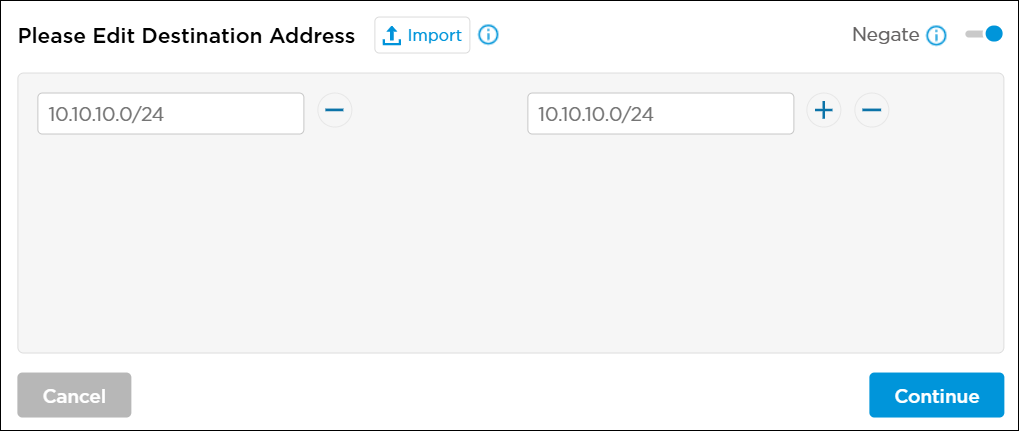
- Click the Negate toggle to select any addresses except the configured addresses.
- Click the Import icon to enter multiple IP addresses separated by commas, and then click Update. Note that this overwrites any existing IP addresses.

- Click Continue
- Select the Address tab to display the address window.
- To specify hostname criteria for a netflow reporting rule:
- Select the Hostname tab to display the Hostname window.

- Click the toggle to enter the source or destination hostname.

- Click Source to enter a source hostname, and then click the icon. To remove a hostname from the list, click the icon.
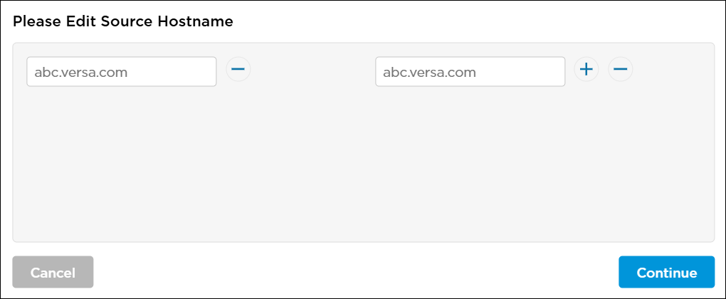
- Click Continue
- Click Destination to enter a destination hostname, and then click the
 icon. To remove a hostname from the list, click the icon.

- Click Continue.
- Select the Hostname tab to display the Hostname window.
- To specify application and application groups criteria for a netflow reporting rule:
- Select the Application tab, and then click Click Here To Add or Modify Applications.
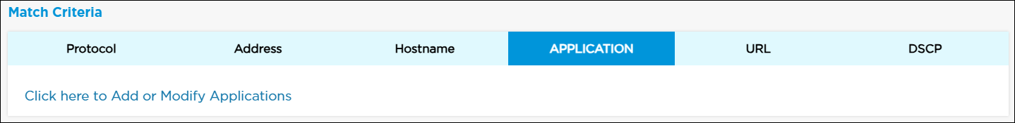
- The Netflow > Rules > Add Application window displays. Select the Applications tab, then select the application to include in the match list, or type the name of the application in the search box and then select it from the search results. Then, click Add.

- Click + Custom Applications to create a new custom application object. For more information, see Add Custom Applications.
- Select the Application Groups tab, and then select predefined application groups to include in the match list, or type the name of the application group in the search box and then select it from the search results. Then, click Add.

- Select the Application tab, and then click Click Here To Add or Modify Applications.
- To specify URL criteria for a netflow reporting rule:
- Select the URL tab to display the URL window.

- In the URL Category section, click Click Here To Add or Modify URLs to select URL categories.
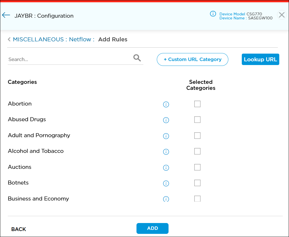
- To add a new custom URL category object, click
 . For more information, see Add Custom URL Categories.
 - Click
 to enter a URL and to look up the mappings to predefined and custom URL reputations and categories. For more information, see Configure Look Up URL Settings.
- To add a new custom URL category object, click
- Click Add.
- Select the URL tab to display the URL window.
- To specify DSCP criteria for a netflow reporting rule, select the DSCP tab and then enter a DSCP value. DSCP allows you to classify and manage network traffic and to provide quality of service (QoS) in Layer 3 networks. It uses the 6-bit differentiated services code point (DSCP) field in the IP header to classify packets.

- Click Save to save the changes to the Titan cloud.
Supported Software Information
Releases 11.3 and later support all content described in this article.
Additional Information
Configure and Activate a Site
Manage Organizational Settings