Configure SD-WAN Traffic Steering
![]() For supported software information, click here.
For supported software information, click here.
When a Versa Operating SystemTM (VOSTM) device in a branch has two or more WAN links, you can configure SD-WAN traffic steering to direct outgoing traffic flows to the desired WAN link. To identify the traffic, you create a traffic steering policy.
In a traffic steering policy, you define rules to classify incoming traffic based on match criteria, such as application, users and user groups, source and destination IP address, and incoming zone. Then, you specify the actions to enforce for traffic that matches the configured criteria.
To enforce the actions for matching traffic, you can apply the following profiles:
- Forwarding profile—Determines how network traffic is forwarded within a network device. In the forwarding profile, you configure the circuit and path priorities, the connection method, load-balancing, and other capabilities to apply for any traffic that matches the rules you configure in the SD-WAN policy.
- TCP optimization profile—Transmission Control Protocol (TCP) is a connection-oriented protocol with traffic management capabilities that focus on reliably delivering traffic to its destination. TCP optimization profiles are configurations or settings that can be applied to TCP to improve its performance in specific network environments.
This article describes how to configure SD-WAN traffic steering policies, forwarding profiles, and TCP optimization profiles in Concerto. You can configure the forwarding and TCP optimization profiles separately, and then reference them in the traffic steering policy, or you can create the profiles inline when you configure a policy.
Create a Traffic Steering Policy
You can create a traffic steering policy as part of a main template, or you can create it separately and then associate it with a main template. For more information on main templates, see Configure Main Templates.
- To create a traffic steering policy for an existing main template:
- In Tenant view, select Configure > SD-WAN > Main Templates.
- Select the main template for which you want to configure the policy.
- Click the workflow step for QoS, Traffic Steering, and Traffic Monitoring (here, step 5). The following screen displays.
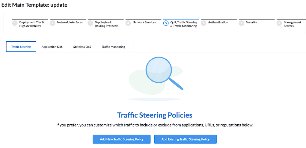
- Click Add New Traffic Steering Policy.
- Continue to Configure Traffic Steering Rules, below.
- To create a traffic steering policy separately from a main template:
- In Tenant view, select Configure > Secure SD-WAN > QoS & Traffic Steering > Traffic Steering.

The following screen displays.

- Click + Add. The Add Traffic Steering Policy screen displays.
- Continue to Configure Traffic Steering Rules, below.
- In Tenant view, select Configure > Secure SD-WAN > QoS & Traffic Steering > Traffic Steering.
Configure Traffic Steering Rules
- In the Add Traffic Steering Policy screen, click Add Traffic Steering Rule.
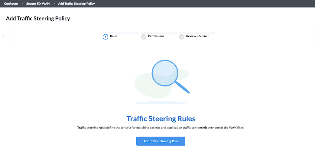
The screen displays the workflow to create a rule, beginning with step 1, Applications and URLs.

- By default, all applications, URLs, and reputations are included in the match criteria. You can include or exclude specific applications, application groups, application categories, URL categories and URL reputations.
To specify traffic for application groups, specific applications, application categories, and URL categories and reputations for the rule:- Select the Applications > Application Groups tab.

- To select specific application groups to include or exclude in the rule, click User Defined Application Groups, Predefined Application Groups, or both. Then select the application groups for the rule to match. You can use the Search bar to find specific application groups.
- To create an Application Group object, click + Add Application Group.
- Select the Applications > Applications tab.
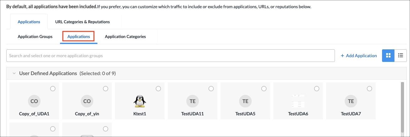
- To select specific applications, click User Defined Applications, Predefined Applications, or both. Then select the applications for the rule to match. You can use the Search bar to find specific applications.
- To create an Application object, click + Add Application.
- Select the Applications > Application Categories tab.
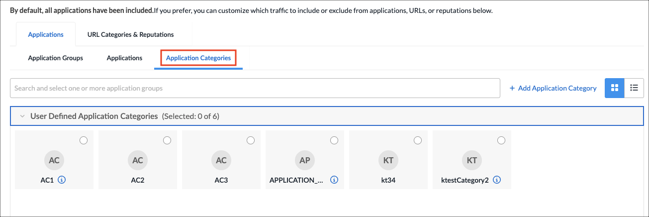
- Select one or more user-defined and predefined application categories for the rule to match. You can use the Search bar to find specific application categories.
- To create an Application Category object, click + Add Application Category.
- Select the URLs and Reputations tab.
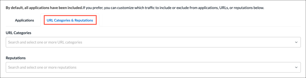
- In the URL Categories field, click the down arrow, and then select one or more URL categories for the rule to match.
- To create a URL category, select + Add URL Category.
- In the Reputations field, click the down arrow, and then select one or more reputations to include in the rule:
- High risk
- Low risk
- Moderate risk
- Suspicious
- Trustworthy
- Undefined
- Select the Applications > Application Groups tab.
- Click Next or select step 2, Users & User Groups.
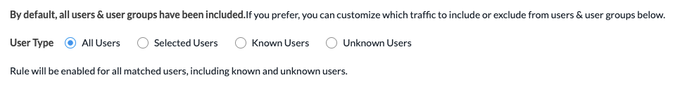
- By default, all users and user groups are included in the match criteria. To customize which traffic to include or exclude from users & user groups:
- Click to select the user type for which you want to apply the rule:
- All Users—Apply rule for all matched users. This is the default.
- Selected Users—Apply rule for selected users.
- Known Users—Apply rule for all known (authenticated) users.
- Unknown Users—Apply rule only for users that are not authenticated.
- If you select the Selected Users option, the following screen displays.
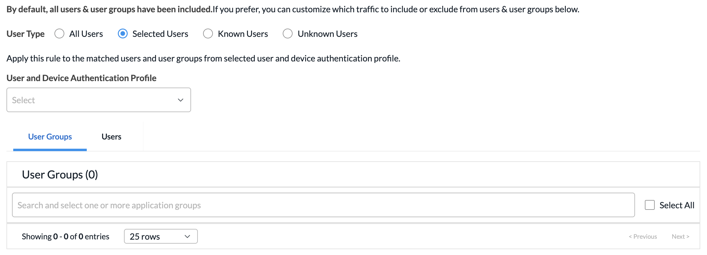
- Click the User and Device Authentication field to select a user authentication profile for the matched users and groups.
- To create a new profile, select + Create New.
- On the User Groups tab, click the checkbox for each user group to include. You can search for specific user groups, or click Select All to include all user groups.
- Click the Users tab, and then click the checkbox for each user to include. You can search for specific users, or click Select All to include all users.
- Click to select the user type for which you want to apply the rule:
- Click Next or select step 3, Source & Destination Traffic.
- By default, traffic from all source and destination addresses and zones, and all sites, are included in the match criteria. You can include or exclude specific source and destination traffic to match the rule.
To match traffic from specific source and destination addresses, zones, and sites:- Select the Source Addresses tab.
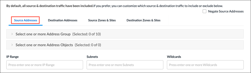
- Select a source address group or address object for the rule to match, or use the search box to find a source address group or object. To exclude the source address or addresses, click Negate Source Address.
- To create an Address Group object, click the + icon. For more information, see Add Address Group.
- To create an Address Object, click the + icon. For more information, see Add Address Object.
- To match on IP range, subnet, or wildcard, enter one or more values in the IP Range, Subnet, or Wildcard fields.
- Select the Destination Addresses tab.
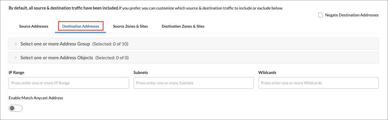
- Select a destination address group or object for the rule to match, or use the search box to find a source address or object. To exclude the destination address or addresses, click Negate Source Address.
- To create an Address Group object, click the + icon. For more information, see Add Address Group.
- To create an Address Object, click the + icon. For more information, see Add Address Object.
- To match on IP range, subnet, or wildcard, enter one or more values in the IP Range, Subnet, or Wildcard fields.
- Click the Enable Match Anycast Address to enable match on an anycast IP address, which is a shared default gateway IP address.
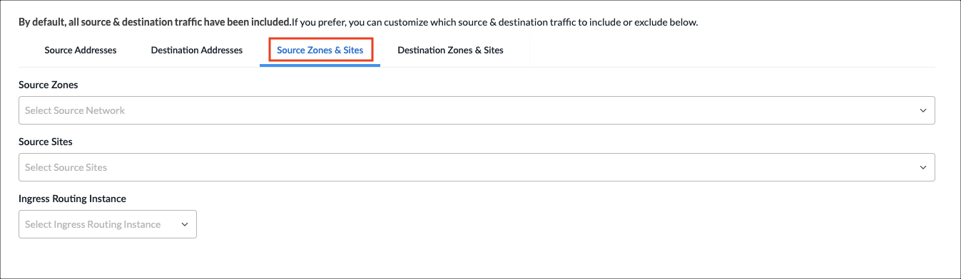
- Select the Source Zones & Sites tab to specify source zones to include in the match criteria. Select one or more source zones or source sites from the lists. You can also select an ingress routing instance.
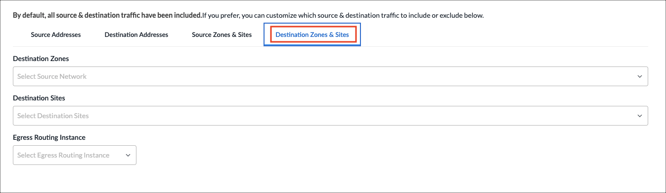
- Select the Destination Zones & Sites tab to specify destination zones to include in the match criteria. Select one or more destination zones or destination sites from the lists. You can also select an egress routing instance.
- Select the Source Addresses tab.
- Click Next to go to step 4, Source and Destination Geolocation.
- Geolocation uses IP addresses to identify the location of connected devices. By default, source and destination traffic from all locations are included in the match criteria. You can specify the source and destination traffic to include or exclude in the match criteria based on geographic location.
To specify the geographic locations to include or exclude:
- On the Source Geo Location tab, click the Country drop-down list to select a geographic category to search.
- In the next field, type the name of the country, state, or city. When a match is found, it is added to the Selected list.
- To remove a country from the list, click the X next to the country name. To remove all selections, click Clear All.
- To exclude the selected geographic locations from the match criteria, click Negate Selection.
- Click the Destination Geo Location tab, and repeat steps 8a through 8d.

- Click Next to go to step 5, Services & DSCP.
- By default, all services, service groups, and DSCPs are included in the match criteria. You can specify the services, service groups, and Differentiated Services Code Points (DSCPs) for the rule to match.
To specify services, service groups, and DSCP to include:- Select the Services tab.
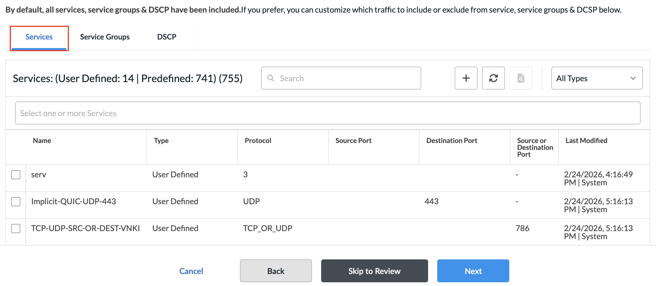
- Select the services to include in the match criteria. To filter the list, click All Types, and select Predefined or User Defined. You can also search by service name.
- To create a services object, click the + icon. For more information, see Add a Service Object.
- Select the Service Groups tab.

- Select the service groups to include in the match criteria. You can search by service group name.
- To create a service group object, click the + icon. For more information, see Add a Service Group.
- Select the DSCP tab. By default, all DSCP decimal values are included in the match criteria. You can specify which DSCP decimal values to include.

- Select one or more DSCP decimal values. The value range is 0 to 63. You can use the search bar to locate values.
- Select the Services tab.
- Click Next to go to step 6, Forwarding Profile and TCP Optimization Profile.
- To define the actions to take on traffic that matches the rule:
- Select the type of enforcement action for traffic that matches the rule:
- Allow—Allow all traffic that matches the rule.
- Deny—Deny all traffic that matches the rule.
- If you selected Allow, enter information for the following fields.

Field Description Forwarding Profile Select a forwarding profile from the list. A forwarding profile is a configuration setting that determines how network traffic is handled and forwarded within a network device.
- To create a forwarding profile, select + Create New.
TCP Optimization Profile (Group of Fields) TCP optimization profiles are configurations or settings that can be applied to TCP to improve its performance in specific network environments. - Mode
Select a TCP optimization mode:
- Auto—Use auto mode when there are two or more VOS devices in the network (dual-ended mode). Auto mode can detect which VOS device is closest to the client and which is closest to the server (peer discovery). It then splits the connection between these two devices.
- Bypass—Disable TCP optimizations.
- Forward proxy—Optimizes data being sent from sent from clients to servers. You configure it on the VOS device closer to the client.
- Proxy—Configure a VOS device to be a proxy for the TCP connection instead of doing end-to-end peer discovery. Proxy mode is similar to splice mode, but you cannot use proxy mode on a hub when the proxy is located behind the hub.
- Reverse proxy—Optimizes data being sent from servers to clients. You configure it on the VOS device closer to the server.
- Splice—Locally splits the TCP connection after an application or URL category is identified or when the VOS device receives the first data packet after the three-way handshake completes. Splice mode is mainly useful for optimizing traffic that is destined to a web proxy at a hub location.
- Bypass Latency Threshold
Enter how much latency must be measured before TCP optimizations begin.
Range: 0 through 60000 milliseconds
Default: 10 milliseconds
- TCP Optimization Profile for WAN
Select a LAN profile.
For proxy mode, you must configure a TCP profile.If you do not select TCP profiles, a system default LAN profile is applied that uses the cubic congestion control algorithm and duplicate ACK loss detection.
- To create a TCP optimization profile, select + Create New.
- TCP Optimization Profile for LAN
Select a WAN profile.
For proxy mode, you must configure a TCP profile.
If you do not select TCP profiles, a system default WAN profile is applied that uses the BBR congestion control algorithm and RACK loss detection.
- To create a TCP optimization profile, select + Create New.
- Select the type of enforcement action for traffic that matches the rule:
- Click Next to go to step 7, Review and Submit.
- In the General section, enter information for the following fields.
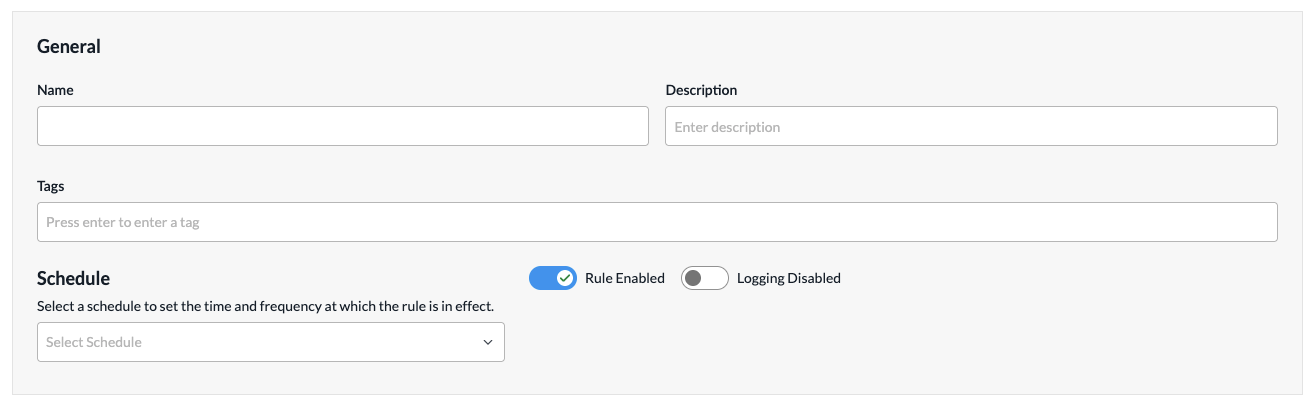
Field Description Name
Enter a name or the rule. Description
(Optional) Enter a description for the rule. Tags
(Optional) Enter one or more tags. A tag is an alphanumeric text descriptor with no spaces or special characters. You can specify multiple tags added for the same object. The tags are used for searching the objects. Schedule
Select a schedule to set the time and frequency at which the rule is in effect. Rule Enabled
Click to disable the rule once it is saved. By default, the rule is enabled. Logging Disabled
Click to the slider bar to enable logging for the rule. By default, logging is disabled. Logging Profile (Group of Fields) If you enable logging, configure the logging profile. - Use Default
Click to use the default logging profile. - Custom
Click to use a custom logging profile, and then select the profile from the Logging Profile field. To add a custom logging profile, go to Configuration > Reusable Objects > Logging Profile. The profile is automatically added to the Logging Profile drop-down list. - Events
Select when to log events:
- Priority Change—Generate a log when the session moves between circuits of different priorities.
- All SLA Violated—Log only when all available paths have violated the SLA.
- Rate Limit—Enter the rate at which to limit log messages.
- Review the remaining sections. Click the
 Edit icon in any section to make changes, as needed.
 - Click Save Traffic Steering Rule. The Add Traffic Steering Policy screen displays the saved rule.

- To add another rule, click + Add in the horizontal menu. You can also select an existing rule and perform the following operations:
- Filter—Click the
 Filter icon to filter on matching IP address or subnet in any address range. You can also filter on service port number. In the drop-down list, select one of the following:
- Select IP Address and enter an IP address or IP subnet, and then click Apply.
- Select Service Port and enter a service port number, and then click Apply.
- Select IP Address and enter an IP address or IP subnet, and select Service Port and enter a service port number, and then click Apply.
- Clone
 —Creates a copy of the rule. You can change the default name of the cloned rule, if desired. The cloned rule then appears in the list of traffic steering rules.
 - Reorder
 —Reorder the selected policy rule.
 - Delete
 —Delete the selected policy rule.
- Filter—Click the
- Continue to Configure Permissions, Review, and Submit the Traffic Steering Policy, below.
Configure Permissions, Review, and Submit the Traffic Steering Policy
- In the Add Traffic Steering Policy screen, click Step 2, Permissions. The following screen displays.
- The permission for each role is selected by default, and you can update it. To change permissions for a role, select or deselect the Create, Read, Update, and Delete fields for the role.
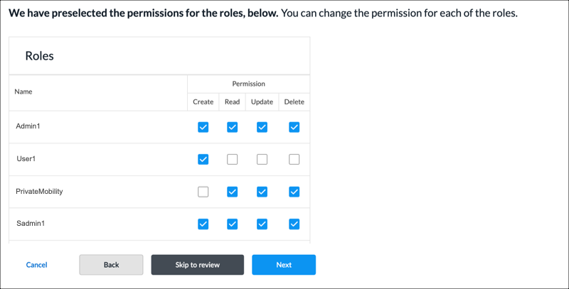
- To change the permissions for a role, select Edit, Hide, or Read in the Permissions column.
- Click Next to go to step 3, Review and Submit.
- In the General section, enter information for the following fields.

Field Description Name Enter a name for the policy. Description Enter a text description. Tags Enter a tag, and then press the Enter key. You can enter multiple tags. A tag is an alphanumeric text descriptor with no spaces or special characters. The tags are used for searching the objects. Reuse Options (For policies added through the Main Templates workflow.) Click Reusable on Other Templates to make the policy usable in other main templates. Otherwise, click Not Reusable. If you mark the policy as reusable, the policy is listed in the Traffic Steering Policies table at Configure > SD-WAN > QoS& Traffic Steering > Traffic Steering. - Review the settings you have selected. Click the Edit icon to change a setting, as needed.
- Click Submit.
Configure a Forwarding Profile
You can configure a forwarding profile as part of a traffic steering policy, or you can configure it separately and then associate it with the traffic steering policy.
- To configure the forwarding profile as part of a traffic steering policy, skip to Step 3 in the following procedure.
- To configure the forwarding profile separately, begin with Step 1.
To configure a forwarding profile:
- Click Configure > Secure SD-WAN > QoS & Traffic Steering > Traffic Steering.
- On the Traffic Steering screen, select the Profiles > Forwarding Profiles tab.
- If you have not yet configured any forwarding profile, then click Add Forwarding Profile.
- If you have configured one or more forwarding profiles, the following screen displays. Click the + Add icon.

The Add Forwarding Profile workflow displays.

- In step 1, Path Selection, select a route path type. The route path type refers to how the next hop is calculated when forwarding the traffic. It can either be a routing lookup, or be decided by an SD-WAN policy rule:
- SD-WAN—For WAN path selection where the next hop is a branch, hub, data center or gateway in the SD-WAN VPN network. The next-hop for the traffic is decided by a routing table lookup.
- Direct Internet and/or Preferred Exit Location—Direct internet refers to the WAN circuit selection for internet breakout traffic at the branch. The preferred SD-WAN exit location refers to the traffic path in the SD-WAN VPN network where the next hop or exit location is a branch, hub, data center or gateway. This exit location is decided by the SD-WAN policy rule configuration and overrides the routing table lookup at the branch.
- To configure an SD-WAN route path for forwarding traffic, enter information for the following fields.

Field Description Connection Priority for Unconfigured Paths Assign a priority for paths that are not configured explicitly:
- 1 through 8
- Avoid—Configure the path as one to avoid. An avoided path is not used even if it is the only available path. If the only available paths are configured as avoid, traffic is dropped.
- Last Resort—Use the when all other paths are down. As an example, you can configure a last resort so as not to use LTE paths when other paths are available.
+ Add Priority (Group of Fields) Click to add a path and priority. The following fields display.
- Priority
Select the path priorities based on WAN connection names, types, or remote site names:
- 1 through 8
- Avoid—Configure the path as one to avoid. An avoided path is not used even if it is the only available path. If the only available paths are configured as avoid, traffic is dropped.
- Last Resort—Use the when all other paths are down. As an example, you can configure a last resort so as not to use LTE paths when other paths are available.
- Connection Mode
Select the connection mode:
- Name
- Type
- Local
If you select the Name WAN connection mode, select a WAN connection name on the local branch:
- Internet-1
- Internet-2
If you select the Type WAN connection mode, select a WAN connection type on the local branch:
- Broadband
- LTE
- MPLS
- Remote
If you select the Name WAN connection mode, select a WAN connection name on the remote branch:
- Internet-1
- Internet-2
If you select the Type WAN connection mode, select a WAN connection type on the remote branch:
- Broadband
- LTE
- MPLS
- To add another path with the same priority value, click the
 Plus icon. To remove a path within the same priority value, click the
 Minus icon.
- To add a path with a different priority value, click + Add Priority.
- To configure a direct internet or preferred exit location route type, enter information for the following fields.

Field Description Next-Hop Selection Method Select how to choose the next hop for DIA traffic:
- Automatic—Select the next hop that provides the best performance based on passively collected performance metrics.
- High-Available Bandwidth—Use high-available bandwidth to load-balance DIA traffic among equal priority next hops.
- Load Balance—Perform equal-cost load balancing among all active next hops at the highest priority level using SLA monitoring and SLA-based path selection metrics.
- Weighted Round-Robin—Use WRR to load-balance DIA traffic between equal priority next-hops.
Next-Hop Failure Action Select the action to take when none of the configured next hops is deemed reachable:
- Failover—Fall back to routing-based path selection.
- Next Rule—Fail over to the next matching rule.
- Wait Recover—Wait for this rule to recover at least one next hop.
Session Pinning to DNS Path Click the toggle to pin all sessions between a client and server to the path of the DNS query that resolved the server. Next-Hop Reevaluate Click the toggle to continuously reevaluate next-hop in the middle of the flow. - Click Next-Hop Priority, and then click + Add Route Path.
- In the Priority field, select a next-hop priority. You can select a value in the range of 1 through 15.
- In the Path Type field, select a path type:
- Preferred SD-WAN Exit Location—Select the traffic path in the SD-WAN VPN network where the next hop or exit location is a branch, gateway, or hub.
- Direct Internet—Select the WAN circuit for internet breakout traffic at the branch.
- Enter information for the following fields, based on the selected path type.
Field Description Preferred SD-WAN Exit Location (Group of Fields) The following fields display for this path type:
- Exit Location
Select the branch as an exit location. - SaaS Application Monitor
Select the SaaS Application Monitor to monitor application performance.
- To create a SaaS Application Monitor object, click + Create New.
- Maximum Latency
Enter a value for the maximum traffic latency, in milliseconds. - Maximum Packet Loss
Enter a percentage value for the total combined forward and reverse packet loss. Direct Internet (Group of Fields) The following fields display for this path type:
- Local Connection
Select the local connection.
- Routing Instance
Select the routing instance. - Next-Hop Address
Enter the next-hop address. - IP SLA Monitor
Select an IP SLA monitor to collects performance metrics related to TCP sessions and export them to Analytics.
- To create an IP SLA monitor object, click + Create New.
- SaaS Application Monitor
Select the SaaS Application Monitor to monitor application performance.
- To create a SaaS Application Monitor object, click + Create New.
- Maximum Latency
Enter a value for the maximum traffic latency, in milliseconds. - Maximum Packet Loss
Enter a percentage value for the total combined forward and reverse packet loss. - Click SD-WAN Path Priority, and then click + Add Priority. Enter information for the following fields.

Field Description Priority
Select the path priorities based on WAN connection names, types, or remote site names:
- 1 through 8
- Avoid—Configure the path as one to avoid. An avoided path is not used even if it is the only available path. If the only available paths are configured as avoid, traffic is dropped.
- Last Resort—Use the when all other paths are down. As an example, you can configure a last resort so as not to use LTE paths when other paths are available.
Connection Mode
Select the connection mode:
- Name
- Type
Local
If you select the Name WAN connection mode, select a WAN connection name on the local branch:
- Internet-1
- Internet-2
If you select the Type WAN connection mode, select a WAN connection type on the local branch:
- Broadband
- LTE
- MPLS
Remote
If you select the Name WAN connection mode, select a WAN connection name on the remote branch:
- Internet-1
- Internet-2
If you select the Type WAN connection mode, select a WAN connection type on the remote branch:
- Broadband
- LT
- MPLS
- To add another path with the same priority value, click the
Plus icon. To remove a path within the same priority value, click the
Minus icon.
- To add a path with a different priority value, click + Add Priority.
- Click Next to go to step 2, Service Level Agreement (SLA).
- Enter information for the following fields.
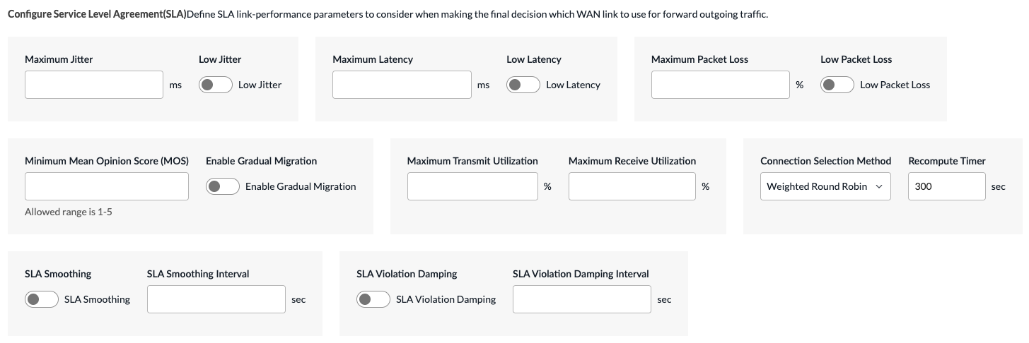
Field Description Maximum Jitter Enter a value for the forward and reverse delay variation (jitter).
Range: 1 to 100 milliseconds
Default: NoneLow Jitter Click the toggle to select a path based on the lowest delay variation (jitter). Maximum Latency Enter a value for the maximum traffic latency (delay). The link latency is a two-way measurement.
Range: 1 to 1000 milliseconds
Default: NoneLow Latency Click the toggle to select a path based on the lowest latency. Maximum Packet Loss Enter a percentage value for the total combined forward and reverse packet loss.
Range: 1 to 100 percent
Default: NoneLow Packet Loss Click the toggle to select a path based on the lowest packet loss. Minimum Mean Opinion Score (MOS) Enter a minimum MOS for audio, video, and voice traffic. The MOS is a measure of the quality of voice data traffic, and it represents the user experience of audio, video, and voice applications. Voice data is always compressed using a codec before it is transmitted, and so the MOS score can vary for the voice data on the same link depending on the codec.
Range: 0 to 5, where 5 represents the best traffic quality
Default: NoneEnable Gradual Migration Click the toggle to enable gradual migration. When traffic flows are moved from a non-SLA-compliant path to an SLA-compliant path, gradual migration allows the traffic flows to move gradually from the original path to the new path over multiple recomputation timer cycles. Maximum Transmit Utilization Enter the percentage of a circuit's available bandwidth to use to transmit traffic.
Range: 1 to 100 percent
Default: NoneMaximum Receive Utilization Enter the percentage of a circuit's available bandwidth to use to receive traffic.
Range: 1 to 100 percent
Default: NoneConnection Selection Method Select how to forward a traffic flow when multiple available WAN paths have the highest priority. For example, if there are two paths at priority 1 and one path at priority 2, one of the priority 1 paths is chosen.
- High available bandwidth—Use the circuit with the highest available bandwidth. Continuing with the example in the previous bullet, because the available bandwidth on WAN2 is higher, this link would be used.
- Path high available bandwidth
- Path weighted round-robin
- Weighted round-robin—Use WRR, which balances flows across paths proportional to their available bandwidth. This is the default connection selection method.
Default: WRR
Recompute Timer Enter how often to re-evaluate the SLA-compliance state of all paths. If the re-evaluation identifies an SLA violation on a circuit, the traffic is switched to a different circuit.
Range: 5 through 1800 seconds
Default: 300 secondsSLA Smoothing Click the toggle to enable SLA smoothing. Enable this option to average the SLA metrics over the smoothing interval instead of the recompute interval. If you do not enable SLA smoothing, the SLA compliance of a path is checked every recompute interval. SLA Smoothing Interval Enter the SLA smoothing interval, in seconds.
Range: 10 through 300 seconds
Default: 120 secondsSLA Violation Damping Click the toggle to enable SLA violation damping. Enable this option to associate the recompute interval value with the damping interval value. If you do not enable SLA violation damping, the SLA compliance of a path is checked every recompute interval. SLA Violation Damping Interval Enter the SLA violation damping interval, in seconds.
Range: 10 through 300 seconds
- Click Next to go to step 3, Path Conditioning.
- To configure forward error correction (FEC) and packet replication, enter information for the following fields.

Field Description Forwarding Error Correction (FEC) (Group of Fields) FEC allows you to control errors in data transmission flows when the communication channels are unreliable or noisy. The sender encodes messages using an error-correcting code (ECC) in a redundant manner, which allows the receiver to correct errors without having to request retransmission. The sender generates an FEC parity packet for every nth packet that it sends. The receiver uses this parity packet to recover any lost packets, minimizing packet loss at the receiving end. - Enable FEC
Click the toggle to enable FEC.
Default: Disabled- Send FEC Packet To
Select the circuit on which to send FEC parity packets:
- Alternate circuit—Send FEC parity packets on a WAN interface that is not an interface on which data packets are transmitted. This is the default. If an alternate circuit is unavailable, FEC parity packets are sent on the same circuit as data packets.
- Same circuit—Send FEC parity packets on the same WAN interface used to transmit data packets.
Default: Alternate circuit
- Duplicate FEC Packet
Select how to duplicate FEC parity packets:
- Alternate circuit—Duplicate FEC parity packets and send them on a WAN interface that is not an interface on which data packets are transmitted.
- Disable—Do not duplicate FEC parity packets. This is the default.
- Same circuit—Duplicate FEC parity packets and send them on the same WAN interface used to transmit data packets.
Default: Disable
- Number of Data Packets per FEC Packets
Enter the number of data packets after which an FEC packet is generated and sent to the peer branch. The generated FEC parity packet can recover a packet on the peer branch only if there is one lost packet in the specified number of packets per FEC.
Range: 1 through 32
Default: 4- Start When
Select when to start sending FEC parity packets:
- Always
- SLA violated—When all available paths are SLA violated.
- Stop When
Click to set the circuit utilization threshold at which to stop sending FEC parity packets. - Circuit Utilization
When you enable Stop When, enter the utilization threshold at which replication stops automatically. Specify this as a percentage of the total circuit bandwidth. When the circuit utilization of the links used for data packets or FEC parity packet transmission exceeds this threshold, FEC stops.
Range: 1 through 100 percent
Default: NonePacket Replication (Group of Fields) Packet replication duplicates, or mirrors, packets and transmits them over multiple paths. If a packet is lost on one link, the mirrored packet is delivered on one or more secondary links. Packet replication provides a way to improve the quality of voice traffic and is recommended for sites whose audio calls are not clear. - Enable Packet Replication
Click the toggle to enable packet replication.
Default: Disabled- Replication Factor
For each ingress packet, define the number of egress packets to send.
Range: 2 through 4
- Start When
Select when to start replication automatically:
- Always
- SLA violated—When all available paths do not meet configured SLA threshold.
- Stop When
Click to enable using a circuit utilization threshold value to stop packet replication. - Circuit Utilization
When you enable Stop When, enter the circuit utilization threshold at which replication stops automatically. Specify this as a percentage of the total circuit bandwidth. When the circuit utilization exceeds this threshold value, packet replication stops automatically.
Range: 1 through 100 percent
Default: None - Click Next to go to step 4, Permissions.
- The permission for each role is selected by default, and you can update it. To change permissions for a role, select or deselect the Create, Read, Update, and Delete fields for the role.
- Click Next to go to step 5, Review and Submit.
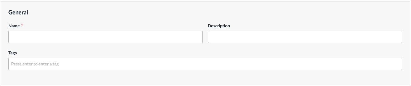
- In the General section, enter a name for the forwarding profile. You can also enter a description and tags. A tag is an alphanumeric descriptor, with no white spaces or special characters, that you can use to search the objects.
- For all other sections, review the information. If you need to make changes, click the
 Edit icon.
 - Click Submit.
Configure a TCP Optimization Profile
TCP optimizations mitigate the effects of high latency and packet loss on the performance of TCP-based applications. The optimizations are based on a TCP proxy architecture in which one or more VOS devices in a network path between a client and server split the TCP connection into two. One connection faces the client and one faces the server, with the VOS devices acting as TCP proxies for each of the split network segments. The optimizations can be done in one of the following modes:
- Dual-ended mode—TCP connection is split between two peer VOS devices in the network path
- Single-ended mode—TCP connection is split independently on one or more VOS devices in the network path.
To configure a TCP optimization profile:
- Click Configure > Secure SD-WAN > QoS & Traffic Steering > Traffic Steering.
- On the Traffic Steering screen, click the Profiles > TCP Optimization Profiles tab.
- If you have not yet configured any forwarding profile, then click Add Forwarding Profile.
- If you have configured one or more forwarding profiles, the following screen displays. Click the + Add icon.

The Add TCP Optimization Profile workflow displays.
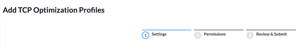
- In step 1, Settings, enter information for the following fields.
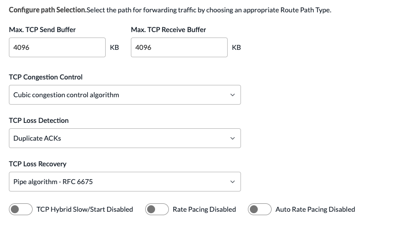
Field Description Name Enter a name for the TCP optimization profile. Max TCP Send Buffer Enter the maximum size of the TCP send buffer. Setting the buffer size limits TCP memory consumption.
Range: 64 through 16384 KB
Default: 4096 KBMax TCP Receive Buffer Enter the maximum size of the TCP receive buffer. Setting the buffer size limits TCP memory consumption.
Range: 64 through 16384 KB
Default: 4096 KBTCP Congestion Control Select the congestion control algorithm to use:
- BBR congestion control algorithm—Bottleneck bandwidth and round-trip propagation time measures both the largest amount of recent bandwidth available to a connection and the connection's smallest recent round-trip delay. BBR then uses these metrics to control how fast it sends data and how much data it allows to be sent at any given time.
- Cubic congestion control algorithm—An algorithm that uses a cubic function instead of a linear window increase function to improve scalability and stability for fast and long-distance networks. This is the default.
- Hybla congestion control algorithm—An algorithm designed to counteract the performance unfairness of TCP connections with longer round-trip-time links, such as satellite or wireless networks.
- New Reno congestion control algorithm—An algorithm that responds to partial acknowledgments.
Default: Cubic congestion control algorithm.
TCP Loss Detection Select the method to use to detect TCP packet loss:
- Duplicate ACKs—Loss detection based on duplicate acknowledgements. Duplicate acknowledgements mean that one or more packets have been lost in a TCP stream and the connection is attempting to recover them. They are a common symptom of packet loss.
- Recent acknowledgment (RACK). RACK uses the notion of time, instead of packet or sequence counts, to detect losses.
Default: Duplicate ACKs
TCP Loss Recovery Select the method to use to recover lost TCP packets:
- Pipe algorithm—Perform TCP loss recovery as described in RFC 6675. This is the default.
- Proportional rate reduction—Perform TCP loss recovery as described in RFC 6937.
Default: Pipe algorithm
TCP Hybrid Slow/Start Click to enable TCP hybrid slow start. Hybrid slow start maintains the TCP slow-start mechanism, which probes network bandwidth and gradually increases the amount of data transmitted until it finds the network's maximum carrying capacity. It also provides a mechanism to help TCP slow-start to exit without incurring a large number of lost packets. By default, hybrid slow start is disabled.
Default: DisabledRate Pacing Click to enable rate pacing. Rate pacing injects packets smoothly into the network, thereby avoiding transmission bursts, which could lead to packet loss. By default, rate pacing is disabled.
Default: DisabledAuto Rate-Pacing Limit Click to enable rate pacing. Rate pacing injects packets smoothly into the network, thereby avoiding transmission bursts, which could lead to packet loss. By default, rate pacing is disabled.
Default: Disabled - Click Next to go to step 2, Permissions.
- The permission for each role is selected by default, and you can update it. To change permissions for a role, select or deselect the Create, Read, Update, and Delete fields for the role.
- Click Next to go to step 3, Review and Submit.
- In the General section, enter a name for the forwarding profile. You can also enter a description and tags. A tag is an alphanumeric descriptor, with no white spaces or special characters, that you can use to search the objects.
- For all other sections, review the information. If you need to make changes, click the Edit icon.
- Click Submit.
Supported Software Information
Releases 13.1.1 and later support all content described in this article.