Configure Regional Hub-and-Controller Nodes for SHHS Topologies
![]() For supported software information, click here.
For supported software information, click here.
In addition to creating templates for hubs and spokes using workflow templates and spoke groups, you can configure hub-and-spoke topologies in a region. In a region, the communication between spoke devices that belong to different regions flows through the hubs in each region. Spokes in the same region can communicate with each other either through region-specific hubs or directly by specifying the topology using spoke groups. This topology is called a spoke-hub-hub-spoke (SHHS) topology.
This article provides an overview of the SHHS topology and describes how to configure it.
SHHS Topology Overview
This section provides an overview of SHHS regions, having multiple spoke groups in a region, and hub–controller nodes.
Regions
You can group hubs and spokes together by configuring them to be in distinct regions. A region consists of hubs, spokes, and Controller nodes.
The following figure shows hubs and spokes deployed in two regions, Region-A and Region-B. In this figure, each region contains two hubs and two spokes. All four hubs connect to top-level Controller nodes, here, Controller-1 and Controller-2. The hubs are connected to each other in a full-mesh topology, and all hubs have established IPsec tunnels among them, indicated by the solid blue lines. All the hubs and spokes have established IKE-based IPsec tunnels with the two Controller nodes, indicated by the dotted red lines. The solid green lines in Region-A represent IPsec tunnels between the spokes and hubs. The solid green lines in Region-B represent IPsec tunnels between the spokes and hubs and between the two spokes.

To deploy hubs and spokes in different regions, you first create a region, as described in the Create a Region section, below.
The hubs and spokes that are deployed in a region tag the routes that they advertise with a special BGP community string, 8011:X, where X is the ID of the region. Spokes in a region accept only routes that contain the region's community string. Hubs in a region accept routes from other regions and re-advertise them to local spokes after adding the local region's community string.
When you configure a hub or a spoke group, you can choose to place them in a region. You can create multiple spoke groups in a region. To have spokes in different regions to be part of the same spoke group, you must configure the region ID on each spoke.
If the entire enterprise network consists of only a single region, it is recommended that you use the region Global (Region ID 1) hub–controllers and spoke groups. Doing this ensures that hub–controllers readvertise the spokes' spoke-to-spoke direct Layer 3 VPN routes within the region.
The following screens show the newly added Region field in the workflow templates and in spoke groups.


Multiple Spoke Groups in a Region
You can create multiple spoke groups in a region. In this topology, each spoke can be part of only one region and one spoke group.
The following figure shows that Region A has two spoke groups, Spoke Group-1 and Spoke Group-2, and that each spoke group has two spokes. Region B has two spoke groups, Spoke Group-3 and Spoke Group-4, each containing two spokes. If a spoke in one region needs to communicate with a spoke in another region, traffic from one spoke first goes through the local hub and then through the remote hub, which then forwards the traffic to the remote spoke.
In this type of topology, you can configure hubs simply as hubs. You cannot configure them as hub–controller nodes. For more information, see Hub-Controller Node, below.

Hub–Controller Node
The Versa Operating SystemTM (VOSTM) node personality hub-controller node (HCN) functions as both a hub and a Controller node, serving the spokes that are in the same region. The following figure shows HCNs deployed in an SHHS topology. Spokes establish IKE IPsec tunnels to the local HCNs. Only HCNs establish IKE IPsec tunnels to the top-level Controller nodes.

For large SD-WAN networks deployed by service providers or enterprises, you can segment the network into multiple regions for better scalability. You can deploy two or more HCNs in each region serving as Controller nodes and hubs for the spokes in the region. You interconnect the hubs using top-level Controller nodes. In a service provider environment, HCNs are typically multitenant and are shared by multiple customers, similar to regular Controller nodes. As with normal hubs, you onboard HCNs using the zero-touch provisioning (ZTP) process. You can onboard additional customer tenants by updating the workflow templates and then committing the changes.
In SD-WAN networks in which there is no direct communication between spoke devices and a staging Controller node, you can configure the HCN as a staging Controller node by selected the Staging value in the template workflow. When you configure an HCN as a staging Controller node, remote spokes can be loaded with boot configurations that make them connect to one of the HCNs for ZTP. As with regular staging Controller nodes, URL ZTP is supported through HCNs.
The following screenshot shows a Hub Controller device type that is configured to be a Staging Controller node. You can add subtenants when you create a template workflow or by editing an existing template workflow and redeploying it.

The following screenshot shows a newly created hub–controller.

Note that if the hub–controller is behind a NAT, you must configure a public IP address when you configure a WAN interface in the SD-WAN site settings so that the spokes can communicate with the HCN. For more information, see Configure SD-WAN Sites.
A spoke group can connect either to a regular hub or to a hub–controller, but not to both. To enforce this requirement, you must select either Hub or Hub–Controller when you configure the spoke group. For backward compatibility, the default spoke group type is Hub
When you create a spoke device using the device workflow, IKE IPsec PSK information is set automatically on the corresponding HCN for each device. When you commit the templates to the HCN devices, the PSK information is preserved on the hubs.
Regional Hub-and-Controller Configuration Overview
To configure a region and hub-and-Controller nodes, you do the following:
- Create a region.
- Deploy a Controller node.
- Associate Controller nodes with an organization.
- Create a template for the hub–Controller node
- Create a device for the hub–Controller node.
- Create a spoke group.
- Create a spoke template.
Create a Region
- In Director view, select the Configuration tab in the top menu bar.
- Select Objects > Regions in the horizontal menu bar.

- Click the
 Add icon. In the Add Region window popup, enter information for the following fields.
.png?revision=1)
Field Description Name (Required) Enter a name for the region. Value: Text string from 1 through 255 characters long
Default: None
Description Enter a text description for the region. Region ID (Required) Enter a region identifier.
Range: 0 through 100
Default: None - Click OK.
Deploy a Controller
- In Director view, select the Workflows tab in the top menu bar.
- Select Infrastructure > Controllers in the left menu bar.

- Click the
 Add icon. The Deploy Controller popup window displays. For the four tabs on this popup window, provide configuration information as described in the following steps. Mandatory information is indicated with a red asterisk. Click Continue to move to the next tab in sequence and Back to move to the previous tab, or select a tab to move directly to its window.
 - Select the General tab, and provide the basic information about the Controller node. Enter information for the following fields.
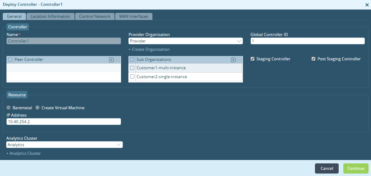
Field Description Name (Required) Enter a name for the Controller node. Value: Text string from 1 through 255 characters long
Default: None
Provider Organization Select a provider organization. Global Controller ID Enter a global Controller identifier.
Range: 1 through 31
Default: NoneResource Select a resource:
- Bare Metal
- Create Virtual Machine
IP Address Enter the management IP address of the Controller. Analytics Cluster Select the Analytics cluster.
+ Analytics Cluster Click to add an Analytics cluster. - Select the Location Information tab. Enter location information, and then click Get Coordinates.

- Select the Control Network tab to configure information about the Controller network. Enter information for the following fields.
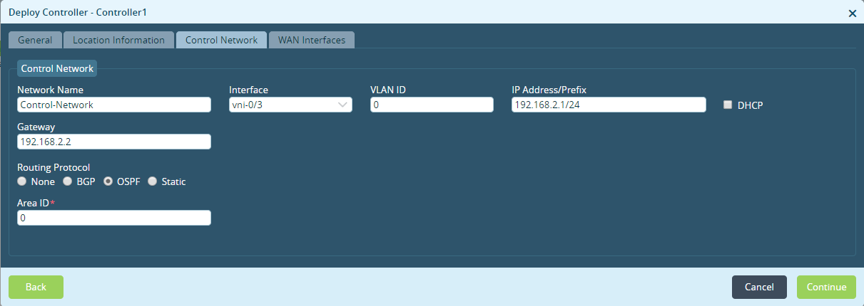
Field Description Control Network (Group of Fields) - Network Name
Enter a name for the network. - Interface
Select the network - VLAN ID
Enter the VLAN ID.
- IP Address/Prefix
Enter the interface's IP address. - Gateway
Enter the IP address of the gateway associated with the IP address.
- Routing Protocol
Select the routing protocol to use:
- None
- BGP
- OSPF
- Static
Area ID (Required) Enter the area ID. - Selct the WAN Interfaces tab to configure information about the WAN interfaces.

- Click Deploy.
Associate Controllers with an Organization
- In Director view, select the Workflows tab in the top menu bar.
- Select Infrastructure > Organizations in the left menu bar.

- Click the
 Add icon. In the Create Organization popup window, enter information for the following fields.

Field Description Name (Required) Enter a name for the organization. Value: Text string from 1 through 255 characters long
Default: None
Global Organization ID Enter a global organization identifier. Parent Select the parent organization. - Select the Controllers tab.
- In the Available pane, click the Controllers to associate them with the organization. The Controllers move to the Selected pane.
- Click Redeploy.
Create a Template for a Hub–Controller Node
- In Director view, select the Workflows tab in the top menu bar.
- Select Template > Templates in the left navigation bar.

- Click the
 Add icon. The Create Template popup window displays. For the eight tabs on this popup window, provide configuration information, as described in the following steps. Mandatory information is indicated with a red asterisk. Click Continue to move to the next tab in sequence and Back to move to the previous tab, or select a tab to move directly to its window.
 - Select the Basic tab to configure basic interface properties. Enter information for the following fields.

Field Description Name (Required) Enter a name for the template. Value: Text string from 1 through 255 characters long
Default: None
Type (Required) Select the template type:
- SD-WAN Post-Staging
- SD-WAN Staging
Organization (Required) Select the organization to which this template applies. Device Type Select the device type:
- Full Mesh—Set the device in a full-mesh topology. This is the default setting.
- Hub—Have the device be a hub in a hub-and-spoke topology.
- Hub Controller—Configure the device to act as a hub and a Controller for the spokes in the specified region (see the description of the Region field below).
- Spoke—Have the device be a spoke in a hub-and-spoke topology. If you select this device type, the Spoke Group field is enabled. Enter the name of the spoke group.
- Staging—Configure the device as a staging Controller when there is no direct communication between spoke devices and a staging Controller. This field is only visible when you select Hub Controller as the device type.
Region For a device type of hub or hub controller, select the region. Redundant Pair Click Enable to create a redundant template, which is required when you are using active–active redundancy.
- Cloud CPE—Click to enable a cloud-based CPE solution for redundancy. You can select Cloud CPE only if you have previously selected VRRP.
- Template Name—Enter the name of the template to use for redundancy.
- VRRP—Click to enable VRRP for the redundant pair.
Suborganizations Click the
 Add icon to associate one or more suborganizations with the template. Select the suborganization from the drop-down list.
To remove a suborganization from the list, select the suborganization and click the
 Delete icon.
When you select the device type as Spoke, the Spoke Group field displays and you can specify a spoke group for the suborganization.
Controllers (Required) Click the
 Add icon to associate one or more Controller nodes with the template. Select the Controller node from the drop-down list.
To remove a Controller node from the list, select the Controller node and click the
 Delete icon.
Subscription (Group of Fields) - Solution Tier (Required)
Select the solution tier that corresponds to the license that the device is using. - Service Bandwidth
Select the bandwidth to use for solution tier that corresponds to the license that the device is using. To aggregate bandwidth, select multiple bandwidths. - Aggregate Bandwidth
If you select multiple service bandwidths, this field displays the total aggregate bandwidth. - Solution Add-On Tier
Select a solution tier for the post-staging template Custom Parameters Enter custom subscription-related parameters:
- Name—Name used to identify the parameter.
- Value—Value of the parameter.
Click the
 Add icon to add the custom parameter to the template
Primary Select if this is the primary solution tier. The license pricing depends on the selected solution tier and service bandwidth.
Unselect if you are applying the template to the standby device in a high availability (HA) pair.
Analytics Enables Select to have the device generate logs on and send logs to Versa Analytics.
Unselect if your deployment does not use Versa Analytics.
Analytics Cluster Select the Analytics cluster to use for the device. + Analytics Cluster Click to create an Analytics cluster. In the Create Analytics Cluster popup window, enter information following fields.
- Cluster Name (Required)
Enter a name for the cluster. - Northbound IP
Enter a name to identify the northbound IP address, enter the IP address for the northbound interface, and click the  Add icon to add the IP address.
- Connector Port
Select the port number to use for the northbound connection. - Collector (Required)
Enter information about the Analytics cluster collector:
- Southbound IP—(Required) Enter the IP address for the southbound interface, and click the
 Add icon to add the IP address.
 - Collector Port—Enter the port number to use on the collector.
Then, click OK.
Preferred Software Version Select the preferred version of the software to deploy on the VOS device. Note that during the ZTP process, the Director node upgrades a branch device to the minimum software version, which is a version that is backwards compatible with up to the two previous software versions. - Select the Interfaces tab to specify the WAN and LAN interfaces. Enter information for the following fields.

Field Description Device Port Configuration (Group of Fields) Configure the ports on the VOS device. - Number of Ports
Select the number of ports on the device. - Port icons
Right click on the port icon, and from the popup window select the type of interface to configure on the port:
- LAN (green)
- Management (yellow)—Port 0 is always the management interface.
- PPPoE (light blue)
- WAN (dark blue)
- WAN and LAN (dark blue and green)
- Unassigned (gray)
- LTE icon
Click the blue LTE port icon to configure LTE on a WAN interface. You can create up to four LTE interfaces on a WAN interface. The VOS device automatically assigns a port number from 100 through 103 to the LTE interface. - WiFi icon
Click the green WiFi port to configure Wi-Fi for the LAN. You can create up to eight WiFi interfaces on a LAN interface. The VOS device automatically assigns a port number from 200 through 207 to the WiFi interface. Note that these interfaces support only DHCPv4. WAN Interfaces (Group of Fields) This section populates when you add WAN interfaces, with one row for each port. - Port Number
Displays the port numbers selected for WAN ports, including PPPoE and LTE interfaces.
If you selected Redundancy in the General tab, port mapping of the redundant CPE is shown. When you select a LAN interface on the Primary device, LAN interfaces are automatically selected on the redundant device.
If the active, redundant CPEs are not connected to the exact same WAN networks, select a cross-connect port on the Primary device.
- Interface
Displays the VNI interface and subinterface numbers selected for the port. - VLAN ID
Enter the VLAN ID for the subinterfaces. To parameterize the VLAN ID, click the  Parameterize icon.
- Network Name
Select the network name for WAN interface. To create a new network name, click + Create WAN Network. - Priority
Link priority for WAN traffic. A default forwarding profile is automatically created that is based on the WAN circuit priority. If you do not assign a priority, the WAN interface is added to the default forwarding profile, but it has no circuit priority.
To parameterize the priority, click the
 Parameterize icon.
- IPv4
Use IPv4 addressing on the WAN interface:
- Static—Use static IP address. When you select Static, a bind-data variable for the interface's static address is automatically generated in the template.
- DHCP—Use DHCP to obtain an IP address.
- IPv6
Use IPv6 addressing on the WAN interface:
- Static—Use static IP address. When you select Static, a bind-data variable for the interface's static address is automatically generated in the template.
- DHCP—Use DHCP to obtain an IP address.
- Allow SSH to CPE
Click to allow an SSH session to the CPE on the underlay IP address of WAN interface. - Link Monitor
Select to monitor the reachability of the next hop or remote IP address on the WAN interface. If the monitored address becomes unreachable, DIA traffic is directed to another WAN interface if possible. - Subinterfaces
Click the  Add button to add a subinterface on the WAN port. Another row is added to the WAN Interfaces table. For the subinterface, configure all the fields described above.
LAN Interfaces (Group of Fields) This section populates when you add LAN interfaces or WiFi ports, with one row for each port. - Port Number
Displays the port numbers selected for LAN ports and WiFi interfaces.
- Interface
Displays the VNI interface and subinterface numbers selected for the port. - VLAN ID
Enter the VLAN ID for the subinterfaces. To parameterize the VLAN ID, click the  Parameterize icon.
- Network Name
Select the network name for LAN interface. - Organization
Select the organization to which the interface belongs. - Zones
Select the zone to which LAN interface belongs. If you do not select a zone, the LAN interface is automatically associated with a zone based on the LAN network name. - Routing Instance
Select the organization's routing instance with which the LAN interface is associated - IPv4
Use IPv4 addressing on the WAN interface:
- Static—Use static IP address. When you select Static, a bind-data variable for the interface's static address is automatically generated in the template.
- DHCP—Use DHCP to obtain an IP address.
- IPv6
Use IPv6 addressing on the WAN interface:
- Static—Use static IP address. When you select Static, a bind-data variable for the interface's static address is automatically generated in the template.
- DHCP—Use DHCP to obtain an IP address.
- Subinterfaces
Click the  Add button to add a subinterface on the WAN port. Another row is added to the WAN Interfaces table. For the subinterface, configure all the fields described above.
 - Click Recreate.
Create a Device Group for the Hub–Controller Node
- In Director view, select the Configuration tab in the top menu bar.
- Select Devices > Devices Group in the left menu bar.

- Click the
 Add icon. In the Add Device Group popup window, enter information for the following fields.
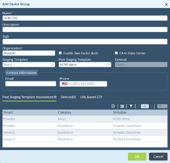
Field Description Name (Required) Enter a name for the organization. Value: Text string from 1 through 255 characters long
Default: None
Organization (Required) Select an organization. Post-Staging Template Select a template. - Select the URL-Based ZTP tab. Enter information for the following fields.
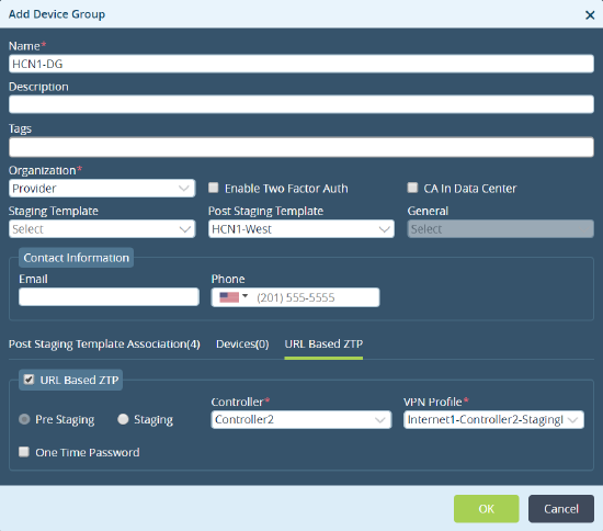
Field Description URL-Based ZTP Select the type of staging:
- Prestaging
- Staging
Controller (Required) Select a Controller node VPN Profile (Required) Select a VPN profile. - Click OK.
Create a Device for the Hub–Controller Node
- In Director view, select the Workflows tab in the top menu bar.
- Select Devices > Devices Group in the left menu bar.

- Click the
 Add icon. The Add Device window popup displays. For the three tabs on this popup window, provide configuration information, as described in the following steps. Mandatory information is indicated with a red asterisk. Click Continue to move to the next tab in sequence and Back to move to the previous tab, or select a tab to move directly to its window.
 - Select the Basic tabto configure basic information about the device. Enter information for the following fields.

Field Description Name (Required) Enter a name for the device.
Organization Select an organization. Deployment Select the deployment type:
- CPE-Bare Metal Device
- CPE-Public Cloud
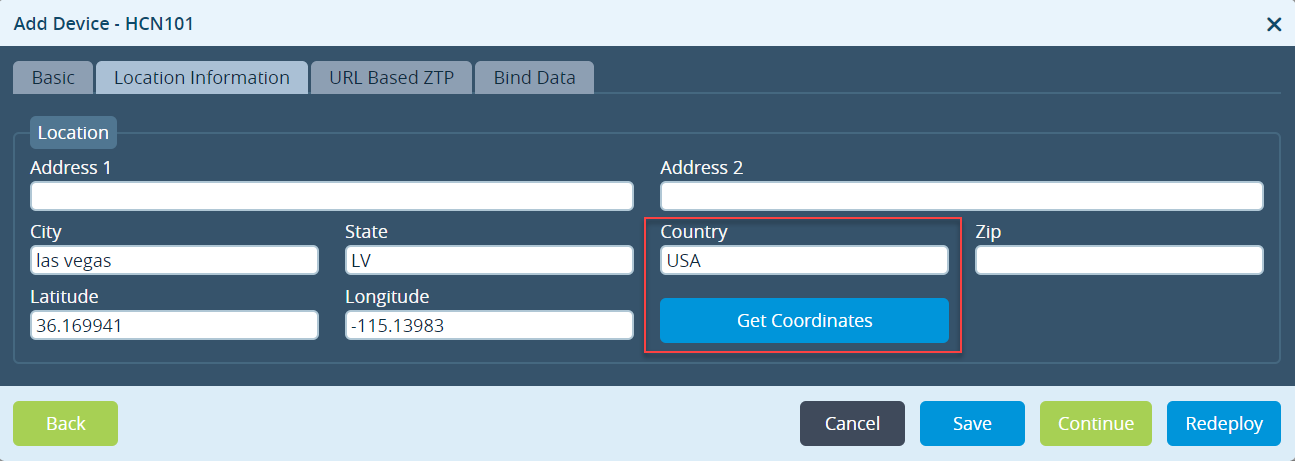
Serial Number Enter the device's serial number. Device Groups Select the device group in which to place the device. - Select the Location Information tab. Select the country and click Get Coordinates.
- Select the URL-Based ZTP tab to specify authentication and network information.

- Select the Bind Data tab to enter the post-staging template details.

- Click Redeploy.
Create a Spoke Group
- In Director view, select the Workflows tab in the top menu bar.
- Select Template > Spoke Groups in the left menu bar.

- Click the
 Add icon to create a spoke group. Enter information for the following fields.

Field Description Name (Required) Enter a name for the spoke group.
Organization (Required) Select an organization. Region Select the region where the spoke group is deployed.
Hub, Hub Controller Click Hub Controller to have the spoke group connect to a hub–Controller node.
Create a Spoke Template
- In Director view, select the Workflows tab in the top menu bar.
- Select Template > Templates in the left menu bar.
- Click the
 Add icon to create a spoke template. The Create Template popup window displays.

- In the Basic tab, select Spoke.
- In the Spoke Group field, select a spoke group.
- Click Recreate.
- Create a device spoke group and a spoke device, as described above.
- Click Save.
Supported Software Information
Releases 20.2 and later support all content described in this article, except:
- Release 20.2.1 adds support for creating multiple spoke groups in a region.
Additional Information
Configure SD-WAN Hubs
Configure SD-WAN Sites
Create an SD-WAN Spoke Group
