Branch Deployment Options
![]() For supported software information, click here.
For supported software information, click here.
The Versa Networks SD-WAN solution offers flexible and comprehensive branch deployment options. This article describes the most common transport-based branch deployment scenarios.
One of the benefits with Versa SD-WAN branch configuration is that each Versa Operating SystemTM (VOSTM) edge device provides the same feature capabilities, regardless of whether it is in a hub, spoke, or any other configuration. You can configure different topologies for different tenants on the same edge device, and at the same time.
Branch with a Single CPE Device and Dual Transports
In the first branch deployment scenario, a customer branch site has a single CPE device that has two different WAN transport links. The following figure illustrates this scenario, showing that a dedicated MPLS connection and an internet connection terminate on the customer's CPE device.
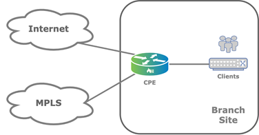
In this topology, overlay tunnels between branches are formed through the MPLS or internet underlay. You configure this functionality using a Director Workflow function. You can use alternate underlays from different providers, such as LTE connections.
You can configure a single CPE branch to support a single organization (also called a tenant) or, as multitenant, to support multiple tenants. The edge device provides full segregation between organizations or tenants. To provide addition segmentation, each organization on the edge device uses virtual routing and forwarding (VRF).
Branch with Active–Active Dual CPE Devices and Dual Transports
A variant of the scenario described in the previous section is a customer branch site that has two CPE devices in an active–active setup, instead of having a single CPE device, and that has two different WAN transport links, Here, the internet link connects to one of the CPE devices (CPE-1 in the figure below) and the MPLS link connects to the other (CPE-2 in the figure). The two paired CPE devices provide high availability (HA) and connect to each other using a cross-connect link.

On LAN side of the CPE device, the Virtual Router Redundancy Protocol (VRRP) provides gateway redundancy. If Layer 2 reachability on the LAN is not available, you can use Layer 3 routing protocols to reach the existing LAN side routers.
Each CPE device in the active–active HA pair maintains overlay connections to the WAN transports on the other CPE device. When the second underlay is physically attached to the other CPE device, it is logically represented on the local CPE device using a cross-connect link. In this deployment model, you can provision each CPE device with SD-WAN policies that leverage all the underlays.
This type of configuration is called active–active HA because both CPE devices always carry traffic to the underlay transport.
Note that state information, including NAT and session state, is not synchronized between the active–active HA CPE devices.
Best Practices for Single or Dual CPE Devices and Dual Transports
The following are best practices for branch deployments that consist of a single CPE device or two CPE devices in an active–active setup, and two WAN transports:
- For security, you should enable next-generation firewall (NGFW) on both CPE devices, because the NGFW and stateful firewall (SFW) software part of the LAN service chain, while the transport interfaces, including the cross-connect link, belong to the transport-VR domain.
- You should enable next-hop monitoring to upstream WAN transport gateway. Alternatively, you can enable a dynamic routing protocol.
- For this scenario, you can use the default Director Workflow for configuration.
Branch with Two CPE Devices and Three Transports
A third branch deployment scenario is a customer branch site has two CPE devices and three WAN links, as illustrated in the figure below. This is another form of the previous scenario, which has two CPE devices and two WAN transports.
The figure shows that the CPE-2 device is configured as a multihomed CPE device that has both internet and LTE connections. The second CPE device, CPE-1, connects only to the MPLS transport domain. You typically use this type of scenario when the LTE connection is required as a backup for the fixed transports.
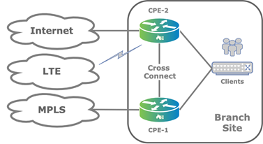
When you deploy the branch CPE devices in active–active HA mode, the LAN side remains the same as described in Branch with Active–Active Dual CPE Devices and Dual Transports. This scenario also works for other combinations of WAN links, up to the maximum of 15 WAN links (for Releases 22.1.1 and later) or 8 WAN links (for Releases 21.2 and earlier) per tenant per device.
Note: Before you add more than 8 WAN links on any one VOS node that you are upgrading to Release 22.1.1, you must upgrade to Release 22.1.1 all the VOS nodes that communicate directly with the one running Release 22.1.1, including the Controller nodes.
Branch HA
To implement HA at a customer branch site, the site must have two VOS edge devices. To provide branch redundancy, VOS devices support two modes of operation: active–active mode and active–standby mode.
Active–active mode, which is stateless, is the more commonly used HA mode. It is simple to deploy and provides better performance during standard operations, because both the VOS edge devices are able to process traffic at all times.
For active–standby mode, which is both stateless and stateful, both underlays for each CPE device are physically connected, and so the cross-connect link is not required. You can configure each CPE device as a standalone CPE device and use VRRP on the LAN side.
There are a few drawbacks to active–standby mode:
- Without the cross-connect, each CPE device cannot take advantage of both WAN transports. As a workaround, you can introduce a Layer 2 switch on the WAN side to allow each CPE device to have access to both WAN circuits.
- During a CPE device failover, stateful connections are lost and TCP sessions are re-established. While the user may not notice the re-establishment of the TCP session, the functioning of some devices may be affected.
In stateful active–standby HA mode, only the active CPE device can forward traffic.
Stateful active–standby HA mode maintains a stateful synchronization between the edge devices. You use this mode when state is important, such as for NGFW and CGNAT traffic.
The following table compares the HA modes.
| Stateless Active–Active Mode | Stateless Active–Standby Mode | Stateful Active–Standby Mode | |
|---|---|---|---|
| Overview |
|
|
|
| Use cases |
|
|
|
| Complexity |
|
|
|
| Available underlays |
|
|
|
| Performance |
|
|
|
| BGP, IPsec, SLA monitoring scalability and state |
|
|
|
| Convergence | |||
|
|
|
|
|
|
|
|
| Traffic restoration |
|
|
|
| Synchronized services between primary and secondary nodes |
|
|
|
| Node synchronized services |
|
|
|
Cross-Connects in an Active–Active HA Topology
The following figure shows an active–active branch HA topology that uses two WAN transport underlays but does not have the dual underlays on the CPE devices.
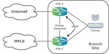
The cross-connect link is a physical connection between the redundant CPE devices that emulates the missing transport domain in a branch and provides redundancy to the attached clients, as illustrated in the following figure.

For the cross-connect link, you configure VLAN tagging for each WAN transport virtual router (VR) instance and you configure IP addresses configured using Workflow templates. Because the WAN transport VRs are distinct routing instances, they allow for reuse of IP addresses.
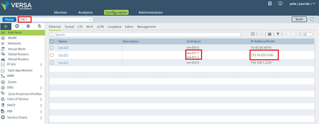
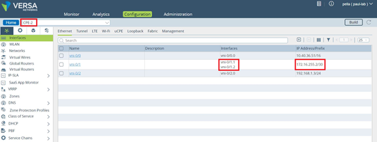
When you enable HA, by default, the back-to-back logical interfaces on the cross-connects are assigned IP addresses from the address range 172.16.255.0/30. The primary CPE device is assigned the address 172.16.255.1, and the second CPE device is assigned 172.16.255.2. Which CPE device is the primary or secondary is determined by which device uses the primary device template that is configured in the Director Workflow. The template for the secondary device is automatically generated by the Workflow.
The following screenshot shows a default HA interface configuration for the CPE-1 device. Notice that the assigned IP address is 172.16.255.1.
The following screenshot shows a default HA interface configuration for the CPE-2 device. Here, the assigned IP address is 172.16.255.2.
You configure static routes in the transport VR of each CPE device, and you use the Workflow to configure ICMP monitoring in the transport VR associated with the cross-connect link to direct traffic destined to the WAN connection of the paired CPE device. The following figure show static route ICMP monitoring with HA.
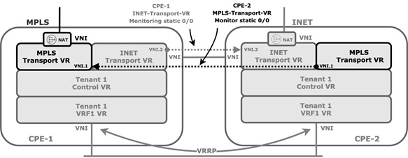
If the cross-connect interface fails over, ir the peer CPE device goes down, or if there is any other IP reachability issue over the cross-connect interface, the static route is withdrawn from the routing table of the corresponding WAN transport VR.
To configure ICMP monitoring on the CPE-1 device that connects to the MPLS transport VR from the CLI:
admin@CPE-1-cli> show configuration | display set | match icmp
set routing-instances INET-Transport-VR routing-options static route 0.0.0.0/0 172.16.255.1 none icmp
set routing-instances INET-Transport-VR routing-options static route 0.0.0.0/0 172.16.255.1 none icmp interval 5
set routing-instances INET-Transport-VR routing-options static route 0.0.0.0/0 172.16.255.1 none icmp threshold 6
To configure ICMP monitoring on the CPE-2 device that connects to the internet transport-VR from the CLI:
admin@CPE-2-cli> show configuration | display set | match icmp
set routing-instances MPLS-Transport-VR routing-options static route 0.0.0.0/0 172.16.255.2 none icmp
set routing-instances MPLS-Transport-VR routing-options static route 0.0.0.0/0 172.16.255.2 none icmp interval 5
set routing-instances MPLS-Transport-VR routing-options static route 0.0.0.0/0 172.16.255.2 none icmp threshold 6
On the LAN side, you use VRRP to elect an active node and a standby node. The logical interface and its virtual IP address is used as the next hop or gateway on the LAN.
DIA in an Active–Active HA Topology
When you configure direct internet access (DIA) in an active–active HA scenario, there are a few things to note.
When you enable DIA, the Director Workflow automates the configuration of BGP peering between the transport VR and the LAN-VR, which is needed to propagate default route.
The ICMP monitoring is between the cross-connect logical interfaces of the CPE-1 internet transport VR and the CPE-2 device and therefore does not protect against internet WAN link failure on the CPE-2 device. This may result in a local internet black hole scenario if the internet WAN link fails on CPE-2, as show in the following figure.

To protect against the local black hole, you must take additional measures, such as monitoring the next next-hop (that is the remote next hop). Doing this may add complexity to the network design, because you may need to use NAT to allow the internet provider WAN interface to reply to ICMP echo requests. The NAT would be necessary because ICMP requests are sourced from the 172.16.255.0/30 prefix range and are not necessarily routed back by the provider router.
The recommended solution is to use dynamic routing over the cross-connect interface between transport VRs to propagate routes and the default route from main transport-VR of each CPE device.
Ports Used in a Branch Active–Active HA Topology
By default, each VOS branch device tries to send SD-WAN traffic using UDP port 4790 as both the source and destination port. However, for an active–active topology, this port cannot be used by the VOS device that is reachable over cross-connect links because active devices cannot both use the same port. However, when the traffic passes through the cross-connect, the source port is NATed to a random port in the range 1024 through 32000.
To change the range of ports used for NATing:
- In Director view:
- Select the Configuration tab in the top menu bar.
- Select Devices > Devices in the left menu bar.
- Select an organization in the left menu bar.
- Select a device in the main pane. The view changes to Appliance view.
- Select the Configuration tab.
- Select Services
 > CGNAT in the left menu bar, select the Pools tab in the horizontal menu bar, and select the CGNAT pool.

- In the Edit CGNAT Pool popup window, select the Port tab.
- In the Allocation Scheme field, select Allocate Port from Range, and then enter the lowest and highest port numbers.
- Click OK.
The following figure illustrates how and where port translation occurs. In this example, for the Branch1A to reach the MPLS transport of the Branch2, it originates SD-WAN traffic from the source address 172.16.255.1:4790 and sends it to the destination address 8.7.6.5:4790. However, because Branch1B is already using 5.6.7.8:4790 as the source address for connections to Branch2, the VOS device performs a NAT translation of the traffic from Branch1A from 172.16.255.1:4790 to 5.6.7.8:1024 (or to a random port number in the range 1024 through 32000).

Supported Software Information
Releases 20.2 and later support all content described in this article, except:
- Release 22.1.1 supports up to a maximum of 15 WAN links per tenant per CPE device.
Additional Information
Configure Virtual Routers
Overview of Configuration Templates
