
Configure IGMP Snooping
 For supported software information, click here.
Internet Group Management Protocol (IGMP) snooping is a Layer 2 network feature that enhances multicast handling within a bridge domain by preventing the unnecessary flooding of multicast traffic. Normally, any multicast packet received on a bridge domain is forwarded to all member ports, regardless of whether the connected hosts are interested in the multicast group. This results in inefficient bandwidth usage and imposes an unnecessary load on end hosts.
With IGMP snooping, the system inspects IGMP Report and Leave messages received from end hosts to identify which ports have active listeners for specific multicast groups. Using this information, the system builds and maintains a multicast forwarding database that associates multicast groups with the set of interested bridge ports.
Although multicast traffic within a bridge domain is switched, the forwarding entries are maintained based on Layer 3 identifiers in the form of (S,G,V) or (*,G,V) tuples, where S is the source IP address, G is the multicast group, and V is the VLAN/bridge domain ID. Only ports that have registered interest in each group are included in the forwarding entry. As a result, multicast traffic is forwarded only to ports with active listeners, while bridge domains fall back to normal multicast flooding when no listener information exists for a group.
IGMP snooping handles multicast traffic in the following ways:
- IGMP snooping restricts the flooding of unknown multicast or unregistered multicast traffic by forwarding this traffic only to multicast designated router (DR) bridge ports. The multicast DR bridge ports can be either statically configured or learned dynamically through a protocol-independent multicast (PIM) hello message. Without IGMP snooping flood restriction, unregistered multicast packets are always flooded to all the member bridge ports of the bridge domain.
- For a pure Layer 2 switch that connects to an upstream Layer 3 router, the IGMP snooping configuration provides the uplink interface over which the protocol-independent multicast (PIM) router can be reached. The IGMP snooping multicast router (mrouter) interface identifies the uplink port that connects to the upstream multicast router. It ensures IGMP queries and multicast control traffic are forwarded correctly toward the Layer 3 router in a pure Layer 2 switching environment.
IGMP snooping is supported on the following Versa Networks platforms:
- Cloud Services Switch 2000 Series
- Cloud Services Gateway 3000 Series
- Cloud Services Switch 4000 Series
- Cloud Services Switch 8000 Series
Configure IGMP Snooping
You can enable IGMP snooping at either the virtual switch level or the bridge domain level. If enabled for a given bridge domain, then any IGMP packets received in the bridge domain must not be flooded. The packets must be sent to the CPU for processing.
Configure IGMP Snooping at the Virtual Switch Level
- In Director view:
- Select the Administration tab in the top menu bar.
- Select Appliances in the left menu bar.
- Select an appliance in the main pane. The view changes to Appliance view.
- Select the Configuration tab in the top menu bar.
- Select Networking > Virtual Switches in the left menu bar. The currently configured virtual switches display.
- Click the
 Add icon. The Configure Virtual Switch window displays.

- On the Virtual Switch Details tab, enter information for the following fields.
Note: For details about how to configure a virtual switch, see the Configure a Virtual Switch with Bridge Domains and Bridge Interfaces section in Configure Layer 2 Forwarding.
Field Description Enable IGMP Snooping Click the checkbox to enable IGMP Snooping, which is disabled by default. When enabled, the switch listens to IGMP Join and Leave messages and forwards multicast traffic only to ports with interested receivers. Last Member Query Interval (sec) Specify the interval, in seconds, to wait for a host response after sending a group-specific query. The IGMP snooping module sends the group-specific query after receiving a Leave message to confirm whether any receivers are still present on the LAN. If no IGMP report is received within this interval, the interface is removed from the multicast outgoing interface list.
Range: 1 through 25 seconds
Default: 1 second
Query Interval (sec) Specify how often the querier device sends general host-query messages.
Range: 1 through 65535 seconds
Default: None
Query Response Interval (sec) Specify how long the querier device waits to receive a response to a host-query message from a host.
Range: 1 through 25 seconds
Default: None
Querier Source Address Enter the source IPv4 address that the switch uses when sending IGMP query messages on the LAN. The switch sends IGMP queries using the configured IPv4 source address when no external multicast router is present. The querier source address is used only in pure Layer 2 environments without PIM.
Note: Only one querier should be active per bridge domain.
Querier Version Enter the IGMP version number of the querier.
Range: 1 through 3
Default: None
Startup Query Interval (sec) Enter the Interval in seconds between queries sent when the IGMP Querier starts or restarts to quickly rebuild multicast group membership.
Range: 1 through 3600 seconds
Default: None
Fast Leave Click the checkbox to remove the IGMP snooping state for a group if an IGMP Leave message is received without sending an IGMP query.
Default: Disabled.
Fast Leave Query Click the checkbox to send rapid group-specific queries after an IGMP Leave message to quickly verify whether any receivers remain before removing the multicast entry.
Default: Disabled.
Configure IGMP Snooping at the Bridge Domain Level
- In Director view:
- Select the Administration tab in the top menu bar.
- Select Appliances in the left menu bar.
- Select an appliance in the main pane. The view changes to Appliance view.
- Select the Configuration tab in the top menu bar.
- Select Networking > Virtual Switches in the left menu bar. The currently configured virtual switches display.
- Click the Add icon. The Configure Virtual Switch window displays with the Virtual Switch Details tab selected by default.
Note: For details about how to configure a virtual switch, see the Configure a Virtual Switch with Bridge Domains and Bridge Interfaces section in Configure Layer 2 Forwarding.

- Click the Add icon in the Bridge Domains section. The following screen displays.

- In the IGMP Snooping section, enter information for the following fields.
Field Description Enable IGMP Snooping Click the checkbox to enable IGMP Snooping, which is disabled by default. When enabled, the switch listens to IGMP Join and Leave messages and forwards multicast traffic only to ports with interested receivers. Last Member Query Interval (sec) Specify the interval, in seconds, to wait for a host response after sending a group-specific query. The IGMP snooping module sends the group-specific query after receiving a Leave message to confirm whether any receivers are still present on the LAN. If no IGMP report is received within this interval, the interface is removed from the multicast outgoing interface list.
Range: 1 through 25 seconds
Default: 1 second
Query Interval (sec) Specify how often the querier device sends general host-query messages.
Range: 1 through 65535 seconds
Default: None
Query Response Interval (sec) Specify how long the querier device waits to receive a response to a host-query message from a host.
Range: 1 through 25 seconds
Default: None
Querier Source Address Enter the source IPv4 address that the switch uses when sending IGMP query messages on the LAN. The switch sends IGMP queries using the configured IPv4 source address when no external multicast router is present. The querier source address is used only in pure Layer 2 environments without PIM.
Note: Only one querier should be active per bridge domain.
Querier Version Enter the IGMP version number of the querier.
Range: 1 through 3
Default: None
Startup Query Interval (sec) Enter the interval, in seconds, between queries sent when the IGMP querier starts or restarts to quickly rebuild multicast group membership.
Range: 1 through 3600 seconds
Default: None
Fast Leave Click the checkbox to remove the IGMP snooping state for a group if an IGMP Leave message is received without sending an IGMP query.
Default: Disabled.
Fast Leave Query Click the checkbox to send rapid group-specific queries after an IGMP Leave message to quickly verify whether any receivers remain before removing the multicast entry.
Default: Disabled.
Static IGMP Groups Select one or more static IGMP groups to statically bind the multicast groups to specific interfaces, bypassing IGMP signaling. This option is useful for devices that do not send IGMP reports and ensures that multicast traffic is always forwarded to the configured interfaces.
Click the
Add icon to add a new static IGMP group, and then enter IPv4 addresses in the Multicast Group and Multicast Source fields.

Click the Interface List
Add icon, then select one or more interfaces to add to the static IGMP group.Multicast Router Interfaces Select one or more multicast router interfaces. Interfaces that are learned or statically configured as mrouter ports are always included in multicast forwarding and are used to forward IGMP control traffic toward the upstream multicast router.
To add interfaces, click the
Add icon and then select one or more interfaces from the drop-down list.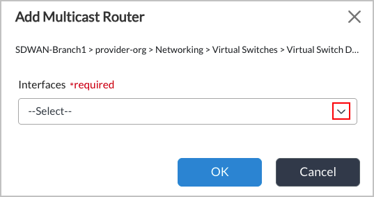
- Click OK.
Monitor IGMP Snooping
To monitor IGMP snooping in Versa Director:
- In Director view, select the Monitor tab.
- Select an organization, and then select the Devices tab.
- Click a device name to display information for the device. In the example screen below, Leaf2 has been selected.

- Select the Networking > IGMP Snooping tab.
- Select a routing instance from the first drop-down menu, and then select one of the following from the second drop-down menu:
- Groups
- Multicast Router
- Querier
- Statistics
- If you select Querier and then click More, a screen similar to the following displays.

- If you select Statistics and then click More, a screen similar to the following displays.

Verification
You can use the following commands to verify the IGMP snooping configuration.
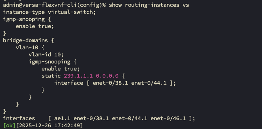
- Display the virtual switch configuration with static IGMP route: show routing-instances vs
-
Display all learned IGMP groups: show igmp-snooping groups
admin@Leaf2-cli> show igmp-snooping groups

admin@Leaf2-cli> show igmp-snooping groups
routing-instance: Tenant1-default-switch
Bridge Domain: Vlan10
Bridge Domain: Vlan20
  Group: 235.0.0.0
   enet-0/6.1 Last reporter:STATIC
    Uptime: 00:49:42 timeout: NEVER
    Include Sources: 10.0.80.10
  Group: 235.0.0.10
   enet-0/6.1 Last reporter
   Uptime:  timeout:
  ok][2026-07-30 17:17:30]
- Display querier information: show igmp-snooping querier
admin@Leaf2-cli> show igmp-snooping querier
Switch Name: Tenant1-default-switch
Bridge Domain Name: Vlan10
  IGMP Snooping Querier is enabled
  Querier IP address         :  192.168.20.250
  Querier version            :  IGMPv2
  Querier uptime             :  00:52:46
  Query interval             :  60 sec
  Max response time          :  20 sec
  Robustness variable        :  2
  Startup query interval     :  31 sec
  Last member query interval :  20 sec
Bridge Domain Name: Vlan20
  IGMP Snooping Querier is enabled
  Querier IP address         :  192.168.20.250
  Querier version            :  IGMPv2
  Querier uptime             :  00:52:46
  Query interval             :  60 sec
  Max response time          :  20 sec
  Robustness variable        :  2
  Startup query interval     :  31 sec
  Last member query interval :  20 sec
 [ok][2026-07-30 17:20:34]
- To display all mrouters configured/learned: show igmp-snooping mrouter
admin@Leaf2-cli> show igmp-snooping mrouter
% No entries found.
[ok][2026-07-30 17:21:39]
- Display statistics: show igmp-snooping statistics
admin@Leaf2-cli> show igmp-snooping statistics
Switch Name: Tenant1-default-switch
Bridge Domain Name: Vlan10
  Queries received           :  0
  Queries sent               :  0
  Reports received           :  0
  Leaves received            :  0
  Group Count                :  0
  Invalid Packets            :  0
Bridge Domain Name: Vlan20
  Queries received           :  0
  Queries sent               :  0
  Reports received           :  717
  Leaves received            :  70
  Group Count                :  32
  Invalid Packets            :  0
 [ok][2026-07-30 17:24:33]
Support Software Information
Releases 23.1.2 (Service Release dated 2026-08-03) and later support all content described in this article.