SD-WAN Solution Architecture
![]() For supported software information, click here.
For supported software information, click here.
SD-WAN Solution Components
As part of its SD-WAN framework, Versa Networks uses the following components:
- At branches, a Cloud Services Gateway (CSG) appliance or a bare-metal appliance running Versa Operating SystemTM (VOSTM) software on a white-labeled x86 network platform or a network interface device (NID0 that is integrated into an x86 platform. Other types of devices leveraged within Versa SD-WAN solution are SD-WAN Gateways.
- Regional SD-WAN Controller nodes, either distributed or centralized, which manage VOS devices (with SD-WAN Controller functionality), Versa Director, and Versa Analytics.
- An optional Versa staging server. A primary objective of the staging server is to ensure that a VOS device that is shipped to a branch for deployment is been received by the proper person.
- Certificate authority (CA)
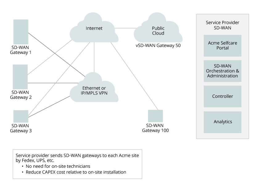
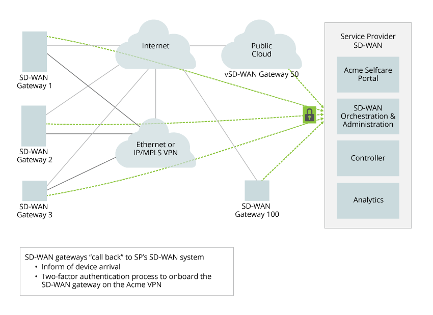
The following illustration shows a logical view of the placement of the SD-WAN components, and it shows a high-level view of the call flow between the components.

The VOS software transforms white-label x86 CPE devices into SD-WAN-enabled CPE devices at remote branches. Note that the same VOS software handles the SD-WAN Controller function.
The SD-WAN Controller node plays a key role in the solution, providing a control plane entry point for branch deployments. The Controller performs the following tasks:
- Onboard the SD-WAN–enabled remote branch CPEs—The Controller authenticates the branch VOS devices using PKI certificates as part of the IKE exchange, and it triggers a two-factor authentication process involving Versa Director.
- Maintain a secure control channel with each remote SD-WAN-enabled CPE—The secure channel established using IKE provides transport between branch devices and all Versa core nodes, including the SD-WAN Controller, Versa Director, and Versa Analytics. The Versa SD-WAN Controller serves as an attachment point for management purposes (Netconf over SSH for pushing configuration templates and service activation) and for control plane information distribution using MP-BGP.
- Distribute BGP updates based on the defined topology to each appropriate VPN and tenant—The SD-WAN Controller nodeuses an advanced, custom, multi-instance MP-BGP route reflector to provide route and security association (SA) information to the branch nodes in the network group on a per-tenant (per-VPN) basis. Each branch node advertises an inbound SA in addition to overlay route information. After the SD-WAN Controller receives the update, it redistributes the BGP route updates, labels (in case of multitenant VPNs), and SA so that destination remote branches can establish secure data channels towards each remote branch office CPE in the same VPN. Based on the configured redistribution policy, the appropriate topology is created dynamically (hub and spoke, full mesh, or partial mesh). Leveraging this framework allows each individual VPN administrator to change the topology and service activation.
- Enable secure IPsec connectivity between branches without the overhead of maintaining a mesh of IKE-based connectivity per branch—This optimization enables avoids the key management and overhead associated with N2 IKE IPsec links and instead utilizes the Controller to distribute SA information. The link between branch an SD-WAN node and the SD-WAN Controller distributes inbound IPsec keys to other branch nodes, to allow all branches to communicate using N+1 keys instead of N2 keys. In a typical deployment, branch nodes are connected to more than one internet or WAN link. Therefore, all communication, post-attach, is enabled using the overlay (loopback) IP address instead of using individual link transport IP addresses provided by each service provider.
You can deploy an SD-WAN Controller node either as bare metal or as a hypervisor-based VM (when you use NFVI). One SD-WAN Controller node is required per SD-WAN. You can deploy multiple Controller nodes in an SD-WAN to provide high availability. Because a VOS device is multitenant, a software instance can serve as an SD-WAN Controller node for up to 256 tenants. Control overlay tunnels from CPE devices and gateways to Controller nodes carry both IPsec and MP-BGP, which form the control plane of the Versa SD-WAN solution. Control plane failures are detected using by the IKE keepalive mechanism (also called dead-peer detection), the MP-BGP hold timer, and BFD. MP-BGP and IPsec IKE for the SD-WAN control plane run only between Controller nodes and CPE devices in a hub-and-spoke topology, which allows the solution to scale to many thousands of CPE devices. If a complete loss of communication occurs between CPE devices or gateways and their Controller nodes, either IKE dead-peer detection or BGP and the BFD keepalive mechanism detect the loss of the SD-WAN solution control plane and forces the CPE-related forwarding plane (that is, the CPE-to-CPE overlay data tunnels) to go down. When a BGP peer is detected as down, the associated routes are withdrawn from the routing and forwarding tables, and the CPE devices and gateways tear down the relevant overlay forwarding (data) tunnels. To mitigate the effects of control plane failure, it is recommended that you deploy redundant Controller nodes and that you use graceful restart. By default, graceful restart is enabled on the Controller node, and it retains the MP-BGP routes for up to 8 hours, thus allowing the forwarding plane to remain up and running even when the Controller nodes are unreachable. You can increase the retention period by modifying the graceful restart multiplier, as described in Configure BGP. By default the multiplier for BGP Controller sessions is set to 8. You can increase the value to one that meets your requirement, for example, to 48 for a 2-day retention period. For ease of management, it is recommended that you configure the same graceful restart timers, including the multiplier, on all Controller nodes.
Onboarding Procedure for an SD-WAN–Enabled CPE Device
Onboarding a new SD-WAN-enabled CPE device occurs in the following stages:
- Pre-attach the VPN
- Pre-attach the VOS device
- Attach the VOS device
Pre-Attach the VPN
When a new VPN is deployed, the following changes are made to the staging server:
- If necessary, accounts for new users are created. These users have credentials that allow them to manipulate the entries on the staging server for the VPN.
- Each VPN is associated with a set of device groups.
- Each VPN and its device group is associated with the following information:
- Contact information of the VPN's CA. The contact is either a fully qualified domain name or an IP address.
- Contact information of the VPN's active and standby SD-WAN Controllers of the VPN. The contact is either a fully qualified domain name or an IP address.
Pre-Attach the VOS Device
When a new VOS device is deployed, the following process occurs:
- Before a VOS device is shipped to a branch, on the staging server, the VOS device is associated with a VPN and device group. The VOS device is identified by its serial number and a Versa-signed certificate.
- The VOS device is preconfigured with a Versa-signed certificate and the contact information of the staging server (either the IP address or fully qualified domain name. The VOS device is also preconfigured to use DHCP to acquire the configuration for its WAN interfaces (IP address, remote gateway, and DNS server).
- When the VOS is received at the branch office, it is plugged into the local network either directly (if an Ethernet leased line is available) or through a modem or router acting as a Layer 2 media converter (if the uplink is a non-Ethernet interface).

- The VOS device uses DHCP to retrieve the IP address, gateway, and other DNS parameters, and it then initiates the bootstrap process towards the staging server. To bypass the use of a staging server, configure the following on the VOS device before you ship it to the branch office:
- Contact information of the VPN's CA. The contact is either a fully qualified domain name or an IP address.
- Fully qualified domain name or IP address of the Versa SD-WAN Controller
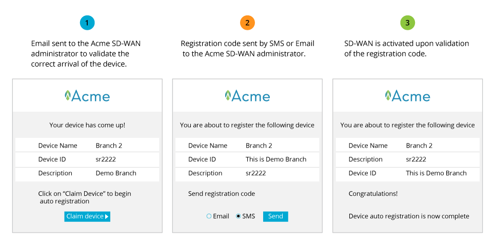
- PKI or preshared key and two-factor authentication are used to verify that the VOS device has been received by the appropriate person. Then the VOS device receives the IP address or fully qualified domain name of the CA and the SD-WAN Controller.

Pre-Attach Call Flow – Option 1

Pre-Attach Call Flow – Option 2

Attach the VOS Device
When the VOS device pre-attach phase completes, the branch VOS device contacts the VPN's CA and replaces the Versa-signed certificate with a network domain certificate that is specific to the VPN. The branch VOS device then establishes IPsec-based secure control tunnels with the SD-WAN Controller. Finally, the VOS devices retrieves an initial configuration from the Versa Director using Netconf over SSHv2.

This initial configuration specifies the following parameters:
- Mechanism to acquire IP addresses on all LAN, WAN, and loopback interfaces. The mechanisms can be DHCP or manual.
- Each access circuit type.
- Each access circuit cost.
- Virtual router forwarding tables (VRFs) and their associated interfaces.
- BGP configuration to communicate with the SD-WAN Controller that is acting as the route reflector.
- Various service configurations, including:
- Access policies for Layer 3, Layer 4, and Layer 7 firewalls.
- DDoS.
- Policy-based forwarding, which defines:
- How to steer traffic in a hybrid WAN based on the following:
- Layer 3 and Layer 4 information
- Layer 7 application
- Time of day
- Tariff cost
- Application's SLA requirements
- What actions to take when an application's SLA requirements are violated. These actions include deprioritizing or dropping traffic belonging to other application categories and rerouting the traffic to a different type access circuit of a different type.
- How to steer traffic in a hybrid WAN based on the following:
- Application quality of service. AppQoS does the following:
- Classifies traffic based on the received Layer 3 and Layer 4 fields and the received Layer 7 applications.
- After classification, associates the traffic with the appropriate forwarding class and packet-loss priority.
- Polices based on a QoS profile associated with the matched AppQoS rule.
- Rewrites, using DSCP or 802.1P, based on forwarding-loss and packet-loss priority.
- NAT, to allow local breakout for some applications.
- DHCP server, to assign IP addresses to devices behind the VOS device.
- Configuration for determining the latency, jitter, and packet loss over various access circuits to other active VPN sites.
- Service chaining
- Within the appliance
- Across appliances in the same site
- Across appliances in different sites in the VPN

The Versa SD-WAN Controller acts as a BGP route reflector. The BGP NLRI and community information is used to create he SD-WAN topology and to establish SD-WAN connectivity. MP-BGP carries traditional information, such as routes and next hops, and Versa has extended MP-BGP to exchange information about key management, access-circuit state, and other states related to the SD-WAN. The MP-BGP key management extension obviates the need to set up IKE-based IPsec tunnels between branch sites. Instead, after each remote SD-WAN CPE branch device receives BGP NLRI and SA information, the CPE device is able to establish IPsec tunnels towards its remote SD-WAN CPE peers.

If you activate SLA monitoring, each SD-WAN-enabled CPE device starts exchanging probes across the overlay VPN network. The CPE device continuously monitors links and applications, including WAN links and web-hosted services, using ITU-T Y.1731 (Ethernet CFM in IP), and it reports bandwidth, latency, jitter, error rate, packet loss, and MTU. Monitoring and collecting this data allows each SD-WAN CPE device to achieve dynamic traffic engineering and application-based link selection. As part of the SLA monitoring process, VOS devices leverage their DPI capabilities, allowing them to do Layer 7 application identification. You enable SLA monitoring by configuring policy-based forwarding in a service template and by configuring AppQoS.
Each SD-WAN CPE device monitors:
- State and status of various access circuits.
- Information about latency, jitter, and packet loss to other VPN sites over the access circuits.
- Information about latency, jitter, and packet loss to non-VPN sites, such as SaaS sites (gmail, Office365, SalesForce) and other sites (such as YouTube and Netflix) over the access circuits.
Using a secure control channel, each SD-WAN CPE device provides its data to the SD-WAN Controller, which, in turn, provides this data to the Versa Director and Versa Analytics nodes. Each VOS device continuously provides monitoring information about its links and services to the Versa Analytics server. The Versa Analytics traffic optimization and reroute applications use this information to perform network-wide global analysis and optimization, and the results of this analysis and optimization are sent to the Versa Director node so that it can take appropriate proactive action.

SD-WAN Gateways
The characteristics, performance, and features of the SD-WAN Gateway are the same as regular SD-WAN CPEs and Controllers. SD-WAN Gateways use VOS software and so support the following capabilities:
- Routing services—Layer 3 customer premises equipment (CPEs), route reflectors, provider edge, carrier-grade NAT, and SD-WAN.
- Security services—Layer 3/ and Layer 4 firewalls, next-generation firewall, (NGFW), intrusion detection and prevention (IDP/IPS), zero-day attack prevention, network antivirus and anti-malware, URL filtering, DDoS protection, application identification and control, and web application firewall.
- VPN services—Site-to-site IPsec VPNs.
- Network services—DHCP server and relay, QoS, VRRP, BFD, and Ethernet OAM.
- Software-defined WAN (SD-WAN) with link SLA monitoring.
- Application delivery controller—Layer 3/ and Layer 4 load balancer.
VOS device performance depends on the underlying hardware.
Versa SD-WAN Gateways use the same VOS device binary package as SD-WAN CPE devices and Controllers, and thus they natively support multitenancy. You can define up to 256 tenants in a single VOS instance.
You implement SD-WAN Gateways to address three common use cases:
- Disjoint Underlay Networks
- Data Center Interconnection
- MPLS Layer 3 VPN Interworking
Disjoint Underlay Networks
While an SD-WAN Gateway is not specifically required for disjoint underlay networks, some recent production networks are using SD-WAN Gateways for these types of networks. Disjoint underlay networks need only an SD-WAN hub (that is, a regular SD-WAN CPE device) to establish the junction between the two different underlay networks. The SD-WAN hub has one or more interfaces in both underlay networks, and it is configured to redistribute the routes learned from the CPE devices in one of the underlay networks to the CPE devices located in other disjoint underlay networks. The SD-WAN CPE hub device is configured with two VRFs, one for importing the original routes (VRF1) from the remote CPE devices and the other for exporting routes to the route target (VRF2). Routes received in VRF1 are leaked into VRF2 and then re-injected to the Controller with a different community and with the hub CPE device as the next hop. This method allows CPE devices belonging to different disjoint underlay networks to communicate via the hub CPE device. The following figures illustrates this concept. The diagram shows the exchange from Branch1 to Branch2. The same process applies from Branch2 to Branch1.

Data Center Interconnection
For the data center or cloud-based infrastructure, you need only to deploy SD-WAN CPE devices: here, the data center is just another site. The deployment framework of an SD-WAN “CPE” in a cloud-based infrastructure or data center is the same as if it were a new remote branch sitting on a private site (including ZTP, SLA monitoring, multitenant VPN, and dynamic service activation), except that the CPE device runs as part of the data center infrastructure. Versa Networks deploys such frameworks for its own internal use within both AWS and Google Cloud Engine.
MPLS Layer 3 VPN Interworking
The main use for SD-WAN Gateways is to interconnect SD-WAN and non-SD-WAN islands.
As previously described, an SD-WAN Gateway is a VOS device instance that acts as a transition point between a regular MPLS VPN domain and the SD-WAN domain. For this purpose, the SD-WAN Gateway is a hybrid branch CPE device that has a presence in both domains so that it can be used as a hub for passing data plane traffic from one domain to the other. A key roles of the SD-WAN Gateway is to authorize the creation of forwarding paths between the two domains so that routing information between the two domains can be distributed appropriately.
You can also use an SD-WAN Gateway to implement a hybrid deployment. In a hybrid environment, all a customer's branch sites have connectivity among themselves, but not all are upgraded with VOS devices to act as SD-WAN CPE devices. This type of deployment can be the desired end state, or it can be a step along the path of a gradual migration of all devices to the SD-WAN environment.
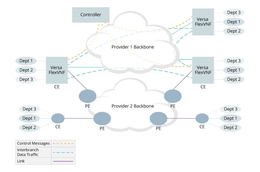
In a hybrid deployment, non-Versa sites can be connected via the MPLS backbone of a single provider or multiple providers using the traditional PE-CE connection model. The diagram below illustrates an example of a hybrid deployment in which some branch sites are connected to the Provider-1 network with VOS devices and other branch sites are connected to the Provider-2 MPLS network using a traditional PE-CE model.

In these deployments, one or more VOS devices act as an SD-WAN Gateway to interconnect two islands of branch sites. A VOS device acting as a Gateway runs OSPF or EBGP sessions with the PE routers and exchanges routes between the two domains. To avoid routing loops, Versa Controller colors the routes that belong to sites connected to the VOS device with a special BGP community attribute. VOS devices advertise to the PE router only those routes with that color. Routes received from the PE router at one site are never advertised, via another VOS device, to the other network.
Let’s look at an example of how to migrate from a full MPLS VPN network to an SD-WAN-enabled network leveraging the existing underlying MPLS VPN architecture. For ease of understanding, we use a simple architecture here. You can build complexity into this example by adding a partial-mesh or hub-and-spoke topology or by adding multitenancy.
The diagram below shows an example where an SD-WAN-enabled site is deployed and needs to communicate with a non-SD-WAN-enabled site (the legacy site in the figure). The customer here is Acme, and it has tenant sites labeled as "AT." An SD-WAN Gateway, which connects to the same VRF as the legacy and SD-WAN sites, receives route updates from the legacy site via the PE to which it is connected (PE2). The SD-WAN Gateway announces this route with a next hop of self to the Controller using a secure control channel (overlay tunnel) over the MP-BGP session running in that secure control channel. Then the Controller, which is acting as a route reflector server, reflects this route with the SD-WAN Gateway as the next hop to its clients, which are the SD-WAN branches connected to PE1. The same process happens on the legacy site, which learns about routes connected behind the SD-WAN site via the SD-WAN Gateway. Those routes have the SD-WAN Gateway as next hop when PE3 redistributes the routes. Finally, the SD-WAN site uses the secure data overlay tunnel already established with the SD-WAN Gateway if it needs to forward traffic to the legacy site. (This tunnel is not shown in the figure.)

The SD-WAN Gateway must remain in place until all the branches are migrated to an SD-WAN architecture. Multiple redundant SD-WAN Gateways can coexist within a network and can be deployed to the required granularity level (for example, per country or per region). An SD-WAN Gateway can be multitenant, connected to multiple VRFs on MPLS PEs. This provides adequate routing policy capability to handle migration needs.
Now, let's add tenants to the SD-WAN architecture. The figure below illustrates the SD-WAN architecture with tenants.

In the figure, MPLS PEs are fully meshed and announce only the directly connected IP subnet of the SD-WAN CPE device. We want to create any-to-any connectivity for the AT 1 VRF that serve only as a transport layer. PE MP-BGP sessions announce only the reachability of the directly connected subnets. Branch VOS devices leverage this transport layer to build both the required secure control channels with Controllers and the data plane overlay tunnel from branch to branch after the secure control channel or channels are established. The BGP sessions that each SD-WAN CPE device brings up with the Controllers run within their own secure overlay tunnel for control plane exchanges, thus providing adequate isolation of routing information distribution. There is one BGP session per tenant within each CPE branch. In the above figure, the multitenant SD-WAN branch, which hosts both Tenant 1 and Tenant 2, has two separate MP-BGP sessions towards the Controller over independent secure overlay tunnels. The BGP sessions and secure tunnels terminate within the appropriate tenant on the Controllers. The Controller reflects information back to the SD-WAN site and thus creates the appropriate topology. Independent of the underlying transport topology (MPLS LSP), Based on the information distributed by the Controller nodes, and independent of the underlying transport technology (such as MPLS LSP), each tenant brings up the required data plane secure overlay tunnels.
After the Controller reflects an update to a branch, a CPE route is installed in the tenant management virtual routers (here, AT MGMT and AT MGMT2), and it is redistributed to the tenant VRFs in which the LAN ports are located.
Supported Software Information
Releases 20.2 and later support all content described in this article.
