Integrate Versa Secure SD-WAN with Netskope Security Cloud
![]() For supported software information, click here.
For supported software information, click here.
This article describes how to integrate Versa Secure SD-WAN with Netskope Security Cloud Platform and deploy Versa Secure SD-WAN and Netskope solutions.
Versa Operating SystemTM (VOSTM) devices integrate with Netskope using a site-to-site IPsec VPN tunnel from the Versa SD-WAN edge device (CPE) to a Netskope secure web gateway (SWG). Versa Director provides workflow-based automation to configure IPsec tunnels from Versa SD-WAN CPEs to Netskope using the Netskope API, and Netskope provides the parameters.
Versa Director supports IPsec tunneling between the CPE and Netskope servers. For multiple LAN VRs configured on the CPE, you can choose one or more VRs from which traffic is forwarded to Netskope servers. For each internet link, a primary tunnel is created to the primary Netskope server and a backup tunnel is created to the secondary Netskope server.
Deploy a VOS Branch in Netskope Using a CMS Connector in Versa Director
This section describes how to create a CMS connector on a Director node to automate bringing up a VOS branch in Netskope, how to configure an IPsec tunnel in a Workflows template, and associate the template with a VOS device using the device workflows.
Before You Begin
Before you begin, you must do the following:
- Create an organization using Workflows in Versa Director.
- Get an access token from Netskope. You need to enter the token ID when you configure the CMS cloud connector in Versa Director. You must send an email to Netskope along with a tenant name to request an access token for the given tenant.
Create a CMS Cloud Connector in Versa Director
To establish a connection between a VOS device and Netskope, and manage that connection through Versa Director, you must first configure a CMS connector on Versa Director. Note that you can create only one CMS connector per tenant for Netskope integration.
To create a CMS cloud connector in Versa Director:
- Log in to Versa Director.
- In Director view, select the Administration tab in the top menu bar.
- Select Connectors > CMS in the left menu bar. The CMS connectors table displays.

- Click the + Add icon. In the Add CMS Connector window, enter information for the following fields.
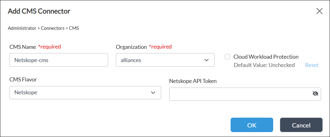
Field
Description CMS Name (Required) Enter the name of the CMS connector. The name is a text string. Organization (Required) Select "alliances" as the organization for the CMS connector. CMS Flavor Select Netskope for the type of cloud device. Netskope API Token Enter the API token ID received from Netskope to access the Netscope server. - Click OK.
Verify the CMS Connector
To verify that a CMS connector is working:
- In Director view, select the Administration tab in the top menu bar.
- Select Connectors > CMS in the left menu bar. The main pane displays the configured CMS connectors.
- Select the CMS connector to verify, and then click
 Validate Connector in the horizontal menu bar. This command triggers an API call to the CMS connector to verify its Netskope Cloud Platform user rights. If the validation is successful, the message "Valid credentials" displays.

Configure a Site-to-Site Tunnel in a Workflow Template for Netskope
- In Director view, select the Workflows tab in the top menu bar.
- Select Template > Templates in the horizontal menu bar.
- Select an SD-WAN post-staging template in the main pane. To create a new workflow template, see Create and Manage Staging and Post-Staging Templates.

- Click Step 3, Tunnels. In the Partner Site-to-Site Tunnels section, click the + Add icon.

- In the Partner Site-to-Site Tunnels window, enter information for the following fields.
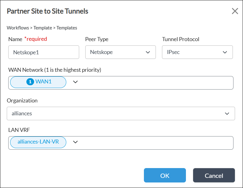
Field Description Name (Required) Enter a name for the site-to-site tunnel. Peer Type Select the Netskope peer type. Tunnel Protocol Select the IPsec tunnel protocol to use to reach the peer. WAN Network Select one or more WAN networks to use. This network is the originating endpoint of the tunnel. The highest priority is 1.
Organization Select the organization for which the site-to-site tunnel is created. LAN VRF Select one or more virtual routing instances to use to reach the LAN. - Click OK, and then click Save.
- If modifying an existing device:
- Click Step 7, Review, and then click Re-Deploy.
- Commit the template.
Configure a Site-to-Site Tunnel in a Device Workflow for Netskope
To configure a Versa Director–Netskope IPsec site-to-site tunnel for a device:
- In Director view, select the Workflows tab in the top menu bar.
- Select Devices > Devices in the left menu bar.
- Select a device in the main pane.

- Click Step 3, Tunnel Information. Select a tunnel name, and then click the
 Add icon. The tunnel displays in the Netskope tunnels list. Note that you cannot configure a public IP address for tunnels created using an IPsec tunnel protocol. To create a new device workflow, see Configure Basic Features.

- In the Configure Site-to-Site Tunnel screen, enter information for the following fields, and then click OK.

Field Description Public IP (Required) Enter a unique IP address. Primary POPS (Required) Select the geographically closest primary Netskope point of presence (POP) in your country. Secondary POPS (Required) Select the geographically closest secondary Netskope point of presence (POP) in your country. Bandwidth (Required) Enter the maximum bandwidth for the IPsec tunnel. - Click Step 5, Bind Data. Select the User Input tab, and then select the Post Staging Template.
- Select Static Routes and enter the static route information.

- Click Save.
- If modifying an existing device:
- Click Step 7, Review, and then click Re-Deploy.
- Commit the template.
Verify IPsec Tunnel Services
To verify IPsec tunnel services for a site-to-site tunnel:
- In Director view:
- Select the Monitor tab in the top menu bar.
- Select Devices in the horizontal menu bar.
- Select a device in the main pane. The view changes to Appliance view.
- Select Tools in the horizontal device menu bar, and then click an interface to view the details.

- Select Services > IPsec in the horizontal device menu bar.
- On the IPsec tab, select IKE History, and then select an IPsec tunnel. Click an entity to view the IKE history.

- Select IKE Security Association, and then select an IPsec tunnel. Click an entity to view the IKE security details.

- Select IPsec History, and then select an IPsec tunnel. Click an entity to view the IPsec history.

- Select IPsec Security Association, and then select an IPsec tunnel. Click an entity to view the IPsec security details.

Supported Software Information
Releases 23.1.1 and later support all content described in this article.