Activate VOS Devices
![]() For supported software information, click here.
For supported software information, click here.
You can activate Versa Operating SystemTM (VOSTM) devices automatically and remotely using zero-touch provisioning (ZTP), and you can also activate a VOS device from the CLI on the device. For VOS devices in a virtual environment, you can use cloud-init functionality to automatically onboard them.
You can use the following methods to activate new VOS devices:
- Global ZTP—Global ZTP allows you to activate multiple VOS devices remotely. The VOS device activation process begins automatically when it powers on. The device uses the call-home feature to connect to a cloud-based staging server. The staging server validates the VOS device and redirects it to a staging Controller node, which completes the activation process. For global ZTP to work, you must provide Versa Networks with the serial numbers of all your VOS devices and the FQDN or IP address of the staging Controller node.
- URL-based ZTP—URL-based ZTP allows an onsite administrator to activate a VOS device. The administrator connects a laptop to the VOS device, or over a wireless network via a mobile phone for WiFi-enabled VOS devices, and clicks an email link to a staging Controller node, which completes the activation process.
- From the CLI—A site administrator can connect to the CLI on a VOS device and run a staging script that activates the device.
- USB-based ZTP—If you have physical access to a VOS device, you can stage the SD-WAN CPE device by inserting a USB storage drive into the device. The USB storage drive must contain a file named staging.params, which contains input parameters for the staging.py script.
For Releases 22.1.3 and earlier, you can configure an SD-WAN edge device, such as a Versa Cloud Services Gateway (CSG) 750, to manage SD-LAN access and core switches. For Release 22.1.4 and later, a streamlined interface lets you configure SD-WAN edge devices using the switch management interface.
Configure an SD-WAN Branch Edge Device to Manage Access and Core Switches (Releases 22.1.4 and Later)
You can use workflow templates to configure an SD-WAN branch edge device, such as a Versa CSG750 appliance, to manage access and core switches. You configure switch management interfaces on the WAN edge device, which provide the device management connection between the SD-LAN switches connected to it and the management Controller node in the SD-WAN network.
The following figure shows a single SD-WAN branch that has two SD-WAN edge devices (Router 1 and Router 2). The two branch devices are configured as an active–active pair. Together, they manage two SD-LAN switches (Switch 1 and Switch 2), and they provide connectivity between the switches and two Controller nodes (Controller 1 and Controller 2).

SD-WAN branch edge devices and the SD-LAN access and core switches use switch management interfaces to communicate with each other in the branch. You must assign native VLAN IDs to the switch management interfaces on each SD-WAN branch edge device that provides connectivity to the access and core switches, and you must configure the same native VLAN IDs to the virtual ports on the switches that connect to the SD-WAN branch edge devices. Note that if there are one or two SD-WAN branch edge device in the branch, you need only one native VLAN to connect the SD-WAN branch edge device to the switches.
Configure the Switch Management Interface
To configure the switch management interfaces on the SD-WAN branch edge device:
- In Director view, select the Workflows tab in the top menu bar.
- Select Template > Templates in the horizontal menu bar, and then select the SD-WAN tab. The screen displays the SD-WAN templates that are already configured.

- Select a provider from the Organization drop-down list, if desired. This focuses the number of templates that display in the window.
- Click a template in the main pane, and then select step 2, Interfaces.

- Select the Switch Management tab, and then click the
 toggle to enable one or more management interfaces.
 - Enter information for the following fields.

Field Description Port Select one or more port numbers to allocate for switch management. VLAN The default native VLAN is 4091. You can overwrite this with any native VLAN you choose. Management VR This is the routing instance that provides connectivity to the Controllers over the WAN interfaces that you selected in the WAN interfaces tab. The switch management VR is created by default to connect to the Controllers. If you want to provide connectivity through another routing instance, select the routing instance from the drop-down list.
Default: Switch-Management-VR
Transport Domain Select the transport domains for the switch to reach the Controller. The options listed for this field are the transport domains for the Controllers associated with the same template. If the Controllers have two transport domains, both are listed. You can select one or both.
- Internet
- MPLS
Switch WAN Interface Priority Table
If you select the Switch-Management VR in the Management VR field, then the WAN interface priority appears. Select the primary WAN interface to use to manage the switch, and then select the secondary WAN interface to use if the primary WAN interface fails. The priority is determined by the order in which you select the interfaces.
Based on the number of WAN networks available in the current template, either some or all can be chosen for the downstream SD-LAN switches. The reachability of the Controllers is propagated from the WAN routing instances to the Switch-Management VR based on the priorities.
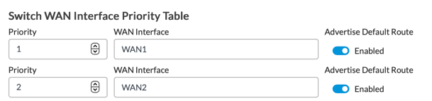
The Advertise Default Route option is disabled by default. Enable the Advertise Default Route option if you want the access switches to be able to connect to other types of servers, such as SNMP and NTP servers. To do so, the switch management VR must receive a default route that is different from the route to the WAN Controller nodes. If the switches only need to communicate with the Controller, you can leave the default, Disabled.
Note: If you select a WAN Interface that does not have a link monitor, a link displays prompting you to add one, as shown below. Click the link and enter the Remote IP in the Link Monitor section of the Edit WAN Interface Port popup.

DHCP Services Choose the type of Dynamic Host Configuration Protocol (DHCP) service that the management interface provides: - None
- DHCP Server
- Relay Server
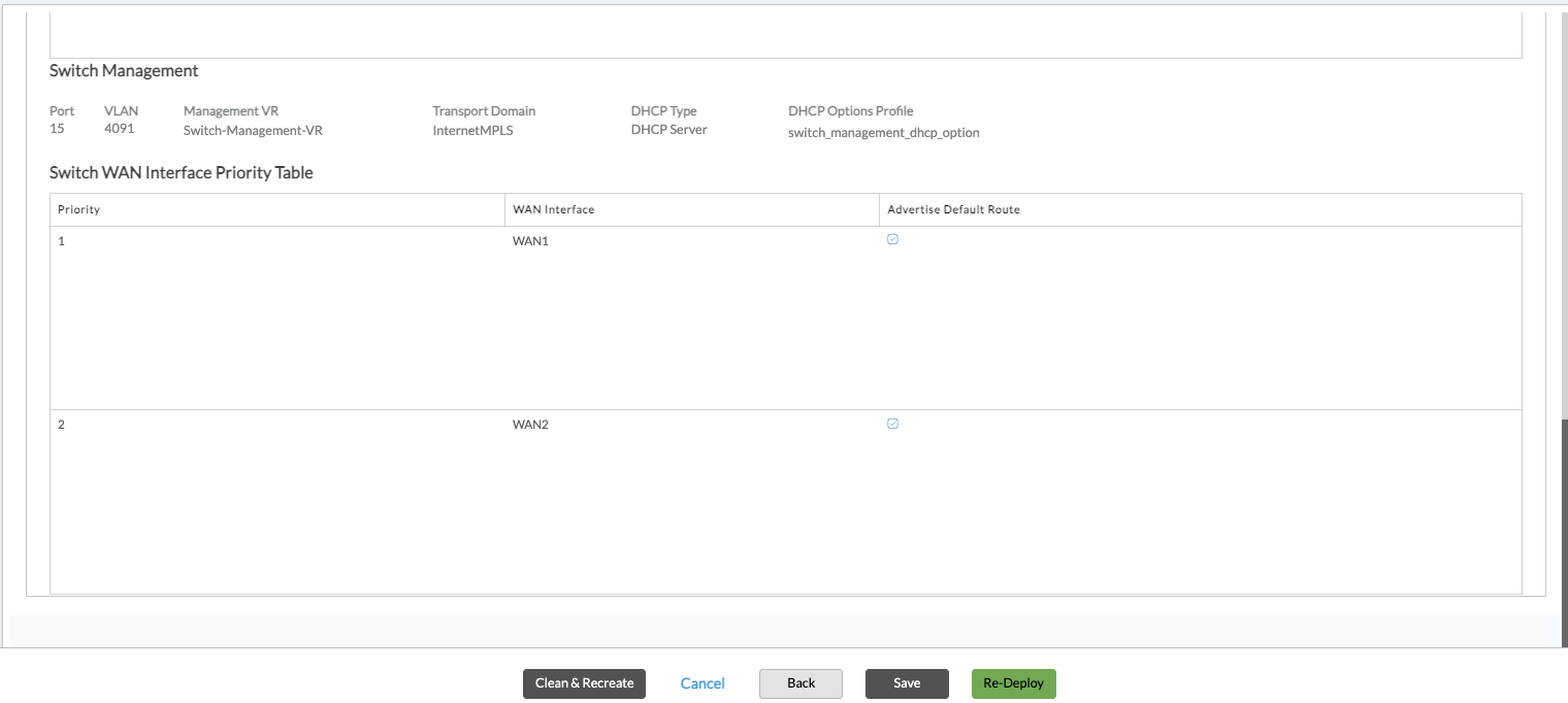
DHCP Options Profile Select the DHCP options profile for the DHCP server to use when allocating IPv4 addresses to DHCP clients. - Click Save.
- You can click Next to continue the workflow configuration until you reach step 8, Review, or you can click Skip to Review.
- Review the updates to the switch management interface and other interfaces on the SD-WAN branch edge device, and then click one of the following:
- Clean & Recreate—Deletes the older contents and deploys the template with the current content.
- Redeploy—Updates the workflow or template in Director so that it reflects the changes made before pushing them out to VOS device.
- Save—Saves the existing and current contents and update the template selections.
Configure the SD-LAN Devices Using Workflows
Access switches must connect to the edge devices in the WAN so that the access switches can reach the Controller node. A branch's WAN edge devices provide WAN connectivity between the access switches and the Controller node. This connectivity is required so that the Director node can provision the access switches using zero-touch provisioning (ZTP).
On the access switch, you configure a device management interface to connect to the WAN edge device. You configure the device management interface for WAN connectivity using the SD-LAN workflow template.
Before you begin this procedure, you must have a template for the access switch. To create a template using the SD-LAN workflow, see Configure SD-LAN Using Workflow Templates.
To configure a device management interface for WAN connectivity:
- In Director view, select the Workflows tab.
- Select Template > Templates in the horizontal menu bar.
- Select the SD-LAN tab, and then select a template for the access switch you want to configure from the Templates subtab.

The Configure Initial screen displays with step 1, Initial, selected by default. Note some field data is automatically imported into the Initial screen.

- Click Next to go to step 2, Interface Configuration. The screen displays the Device Port configuration and port configuration tabs.

- Click the Switch Management Ports tab.
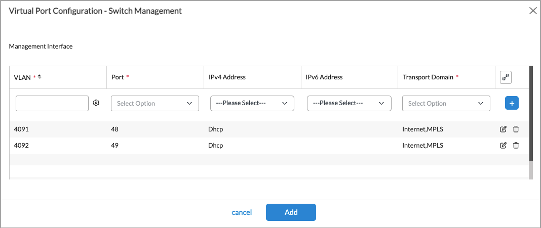
- Select the native VLAN, for example, 4091. The Switch Management - Virtual Port Configuration popup displays.

- Enter the information for the following fields and click Add.
Field Description Management Interface Native VLAN Enter the VLAN ID to use to connect the WAN edge device. This must match the Native VLAN ID that you configured for the switch management interface on the WAN edge device. It is recommended that you use VLAN ID 4091.
IPv4 Address Select the IPv4 address:
- DHCP—Dynamically assign the IPv4 address. You can select this option if the switch is connecting to a Versa or a non-Versa WAN edge device.
- Static—Assign an IPv4 address. You can select this option if the switch is connecting to a WAN edge device that is not a Versa device. Do not select it if the switch is connecting to a Versa WAN edge device.
IPv6 Address Select the IPv6 address, if needed:
- DHCP—Dynamically assign the IPv6 address. You can select this option if the switch is connecting to a Versa or a non-Versa WAN edge device.
- Static—Assign an IPv6 address. You can select this option if the switch is connecting to a WAN edge device that is not a Versa device. Do not select it if the switch is connecting to a Versa WAN edge device.
Transport Domain Select the transport domains for the switch to reach the Controller node. This field lists the transport domains for the Controller nodes associated with the same template. If the Controller nodes have two transport domains, both are listed, and you can select one or both.
- Internet
- MPLS
Uplink/Downlink Management Ports Click the ports in the image or manually add port numbers you want to configure. - You can click Next to continue the workflow configuration until you reach step 8, Review, or you can click Skip to Review.
- Review the updates to the physical ports, including the Switch Management Ports, on the SD-LAN device, and then click Save or Deploy.
Configure an SD-WAN Branch Edge Device to Manage Access and Core Switches (Release 22.1.3)
You can use workflow templates to configure an SD-WAN branch edge device, such as a Versa Cloud Services Gateway (CSG) 750, to manage access and core switches. You configure Layer 2 interfaces on the WAN edge device to provide the device management connection between the SD-LAN switches connected to it and the management Controller node in the SD-WAN network.
The following figure shows a single SD-WAN branch that has two SD-WAN edge devices (Router 1 and Router 2). The two branch devices are configured as an active–active pair. Together, they manage two SD-LAN switches (Switch 1 and Switch 2), and they provide connectivity between the switches and two Controller nodes (Controller 1 and Controller 2).

SD-WAN branch edge devices and the SD-LAN access and core switches use VLANs to communicate with each other in the branch. You must assign VLAN IDs to the Layer 2 interfaces on each SD-WAN branch edge device that provides connectivity to the access and core switches, and you must configure the same VLAN IDs to the virtual ports on the switches that connect to the SD-WAN branch edge devices. Note that if there is only one SD-WAN branch edge device in the branch, you need only one VLAN to connect the SD-WAN branch edge device to the switches.
To configure an SD-WAN device to manage switches, you use both the SD-WAN and SD-LAN Workflows. For SD-WAN, you configure Layer 2 interfaces, and you create a monitor on each WAN interface to use to manage the access switches. For the SD-LAN, you configure a device management interface on the switch to connect to the SD-WAN.
Configure Layer 2 Interfaces
To configure the Layer 2 interfaces on the SD-WAN branch edge device:
- In Director view, select the Workflows tab in the top menu bar.
- Select Template > Templates in the horizontal menu bar, and then select the SD-WAN tab. The screen displays the SD-WAN templates that are already configured.
- Click a template in the main pane, and then select step 2, Interfaces.
- Select the Interfaces tab. The following screen displays.
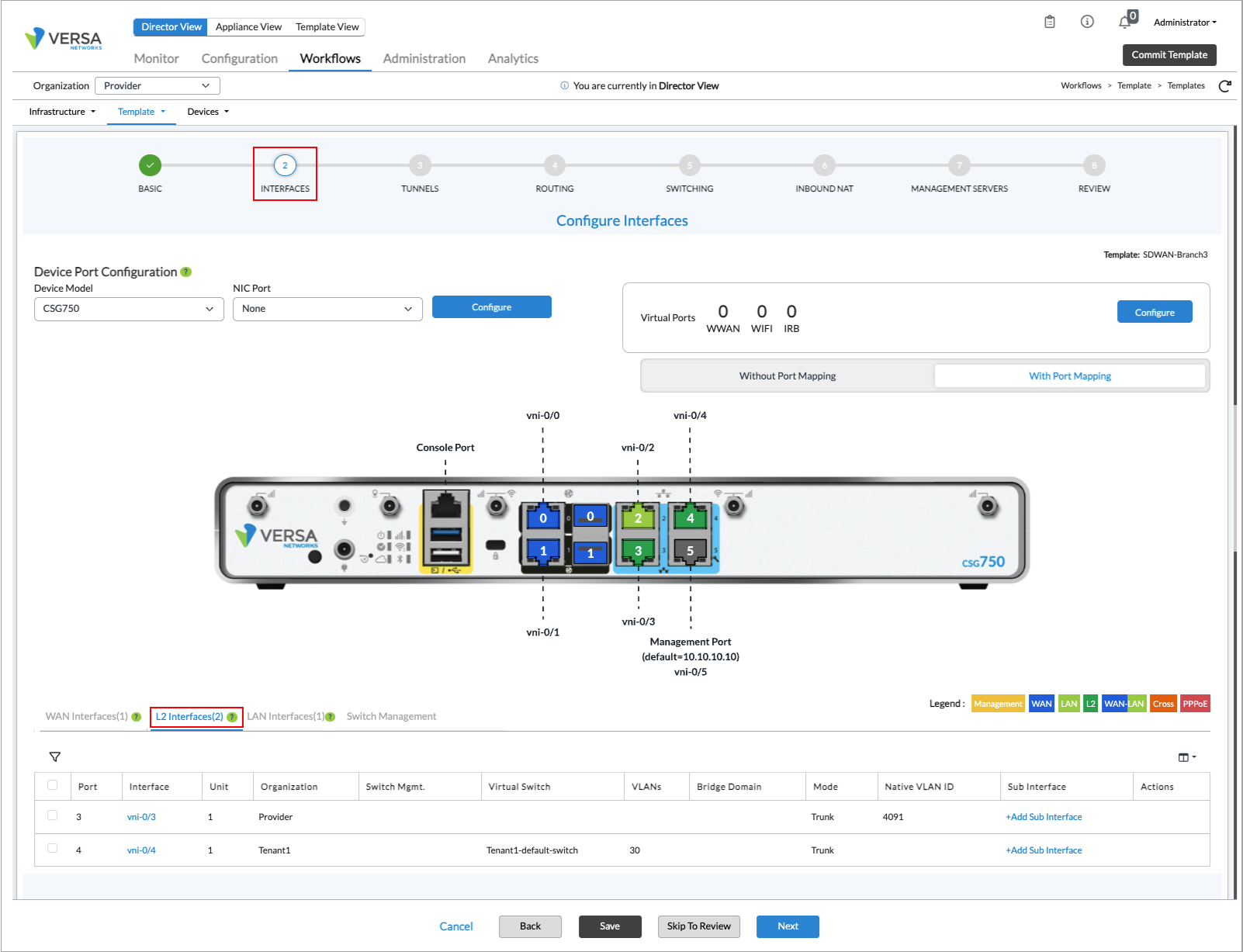
- Click the L2 Interfaces subtab, which displays the Layer 2 interfaces that are already configured.
- Click an interface name. The Edit Layer 2 Interface popup window displays.
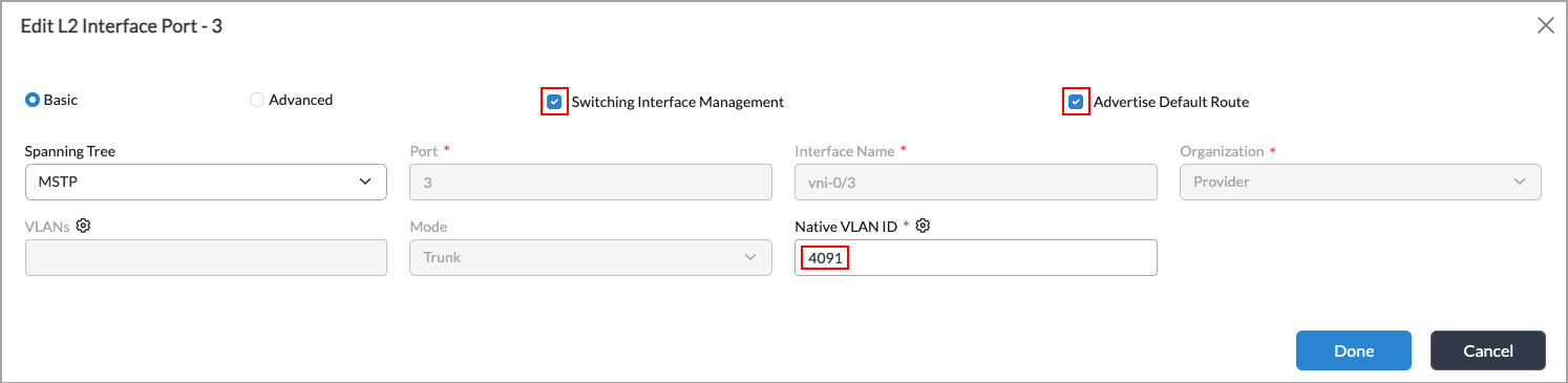
- To create a LAN VR on the SD-WAN branch device, click Switching Interface Management. This LAN VR provides connectivity between the access switches and the Controller nodes.
- To allow the access switches to be able to connect to other types of servers, such as DNS and DHCP servers, click Advertise Default Route so that the switches advertise a default route to the servers.
- In the Native VLAN ID field, enter a VLAN ID. It is recommended that you use VLAN ID 4091 or 4092. If you choose a different VLAN ID, ensure that you use the same VLAN ID in the SD-LAN configuration. For more information, see Configure the SD-LAN Devices Using Workflows, below.
- Click Done.
Select the WAN Interfaces To Manage the Access Switches
To select the WAN interfaces to use to manage the access switches and assign a priority to each interface:
- In Director view, select the Workflows tab in the top menu bar.
- Select Template > Templates in the horizontal menu bar.
- Select Template in the horizontal menu bar, and then select the SD-WAN tab.
- Select step 5, Switching.

- In the Switch WAN Interface Priority Table, select the primary WAN interface to use to manage the switch, and then select the secondary WAN interface to use if the primary WAN interface fails. The priority is determined by the order in which you select the interfaces. In the screenshot above, WAN1 is listed first, so it is the primary WAN interface and WAN 2 is the secondary WAN interface. If WAN1 fails, WAN2 takes over the management of the switch.
- Click Save.
Create a Monitor on the WAN Interfaces
To determine whether the WAN interfaces are up or down, and to provide the proper SLA connectivity from the access switches towards the Controller nodes, you configure a monitor on each of the WAN interfaces that you are using to manage the access switches.
To create a monitor on an WAN interface to use to manage the access switches:
- In Director view, select the Workflows tab in the top menu bar.
- Select Template > Templates in the horizontal menu bar.
- Select Template in the horizontal menu bar, and then select the SD-WAN tab. The main pane displays the templates that are already configured.

- Select the template that includes the WAN interfaces that you are using. The following screen displays.

- Select step 2, Interfaces, select the WAN Interfaces tab, and then click a WAN (vni) interface. The Edit WAN Interface Port popup window displays.

- In the Link Monitor field, enter the IP address of a remote device to monitor to ensure that the WAN interface is up and can reach the device in the cloud. If the WAN interface is down and cannot connect to the remote device, the next WAN interface listed in the Switch WAN Interface Priority Table becomes the primary WAN interface.
- Click Done.
- Repeat steps 5 through 7 on the second WAN interface.
- Click Done.
Configure the SD-LAN Devices Using Workflows
Access switches must connect to the edge devices in the WAN so that the access switches can reach the Controller node. A branch's WAN edge devices provide WAN connectivity between the access switches and the Controller node. This connectivity is required so that the Director node can provision the access switches using zero-touch provisioning (ZTP).
On the access switch, you configure a device management interface to connect to the WAN edge device. You configure the device management interface for WAN connectivity using the SD-LAN Workflows template.
Before you begin this procedure, you must have a template for the access switch. To create a template using SD-LAN workflow, see Configure SD-LAN Using Workflow Templates.
To configure a device management interface for WAN connectivity:
- In Director view, select the Workflows tab.
- Select Template > Templates in the horizontal menu bar. The Template screen displays.
- Select the SD-LAN tab, and then select the Templates subtab. The screen displays the templates that are already configured.
- Select the template for the access switch you want to configure. The Configure Initial screen displays with step 1, Initial, selected by default.

- Select step 2, Interface, or click Next at the bottom of the screen. The step 2, Interface screen displays with the Physical tab selected by default.

- Select the Virtual tab in the horizontal menu bar. The Virtual Port Configuration screen displays.

- If you have already configured a switch management interface on the switch, click Edit in the Switch Management field. Otherwise, click Add. The Virtual Port Configuration—Device Management popup window displays.
- Enter information for the following fields.
Field Description VLAN Enter the VLAN ID to use to connect the WAN edge device. This must match the Native VLAN ID configured for the Layer 2 interface on the WAN edge device. It is recommended that you use VLAN ID 4091 or 4092.
Port Select the port number.
IPv4 Address Select the IPv4 address:
- DHCP—Dynamically assign the IPv4 address. You can select this option if the switch is connecting to a Versa or a non-Versa WAN edge device.
- Static—Assign an IPv4 address. You can select this option if the switch is connecting to a WAN edge device that is not a Versa device. Do not select it if the switch is connecting to a Versa WAN edge device.
Transport Domain Select the transport domains for the switch to reach the Controller node. This field lists the transport domains for the Controller nodes associated with the same template. If the Controller nodes have two transport domains, both are listed, and you can select one or both.
- Internet
- MPLS
 Add
AddClick to add the interface. - If the access switch connects to a second WAN edge device in the branch, repeat Step 8 to add a second device management interface. You must use a different VLAN ID for each WAN connection.
-
Click Add.
Use Global ZTP To Activate a VOS Device
Global ZTP activates a VOS device automatically when the device powers on. After the device powers on, it connects to the internet and obtains its WAN IP address, gateway, and name-server server information using DHCP. Then it uses the call-home feature to connect to a cloud-based staging server. The staging server validates the VOS device's owner (generally either an enterprise or a service provider) and redirects the device to the enterprise's or service provider’s staging Controller node, which completes the activation process. The VOS device communicates with the staging Controller node over an IPsec IKE connection. For this initial connection, authentication is done using public key infrastructure (PKI). Each VOS device has a Versa signed certificate, and the private key is stored in the device's Trusted Platform Module (TPM) chip. After the initial staging process, you can replace this signed certificate with one that is signed by your certificate authority (CA).
For global ZTP to work, you must provide Versa Networks with the serial numbers of all your VOS devices and the FQDN or IP address of the staging Controller node. Versa Networks then creates an inventory entry for the VOS device, which is used by the Versa Networks prestaging server to validate the device when it powers on. If you know the FQDN or IP address of the post-staging Controller node, you can provide this information instead, to skip the provider prestaging step (Step 2 below).
Note that global ZTP is supported only in VOS releases that have not reached end of life (EOL) or end of support (EOS). For more information, see Versa Networks Software Release Lifecycle and End-of-Life Policy.
Using global ZTP to activate a VOS device occurs in three steps, as illustrated in Figure 1:
- Versa Networks prestaging—When the VOS device powers on, it connects to the Versa Networks staging Controller node. Based on the information in the inventory, the Versa Networks staging Controller node validates the VOS device and redirects it to the staging Controller node of the enterprise or service provider. The VOS device then reboots.
- Provider prestaging—The enterprise or service provider claims the device, prompts for authentication using two-factor authentication, and redirects the VOS device to its staging Controller node. The VOS device then reboots.
- Provider staging and post-staging—The enterprise or service provider authenticates the VOS devices using preshared keys (PSK) or public key infrastructure (PKI), and then the VOS device onboards customers (tenants). Then, IKE sessions are established between the provider and tenants. If you skipped the provider prestaging step, you claim the device here: you are prompted for authentication using two-factor authentication before tenants are onboarded. Note that the staging process takes only a few minutes, so rekeying the IKE and IPsec keys during this process is not necessary. However, after staging completes, IKE and IPsec generate new keys to use for the control and data path connections.
Figure 1: Global ZTP
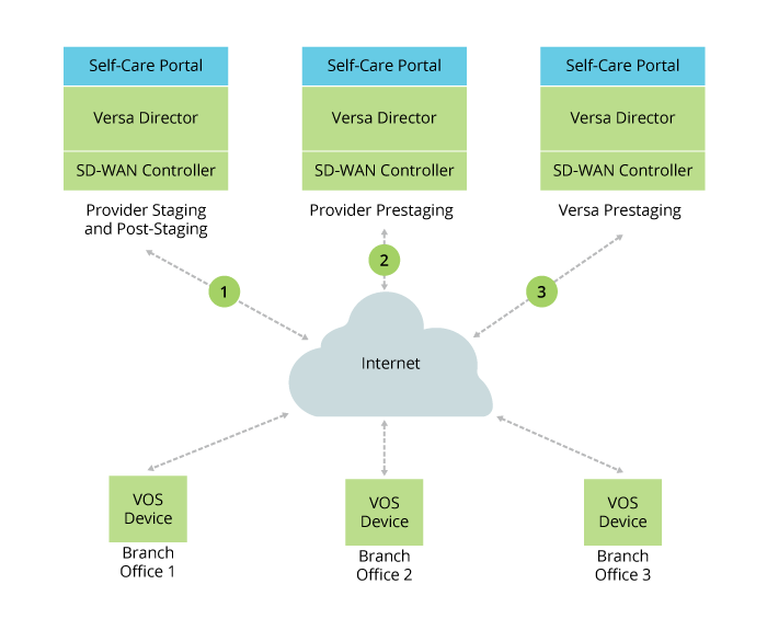
Figure 2 illustrates the device activation flow.
Figure 2: Versa Networks Device Activation Call Flow

To activate VOS devices using global ZTP:
- Ensure that you have created a public Controller node for the VOS devices to connect to. After the VOS device boots, it connects to the Versa Networks cloud-hosted staging Controller node.
- Log in to the cloud-hosted Versa Director.
- Select the Configuration tab in the top menu bar.
- Select Templates > Device Templates in the horizontal menu bar.
- Select one of the following standard templates to use to associate bind data with the VOS devices you are activating:
- Versa Prestaging—Select if the device uses another prestaging Controller node. This template includes bind data for the global tenant ID, preshared key authentication parameters for the prestaging Controller node, and the IP address of the prestaging Controller node.
- Versa Staging—Select if the device uses a post-staging Controller node whose IP address you know. This template includes bind data for the global tenant ID, preshared key authentication parameters for the staging Controller node, and the IP address of the staging Controller node.
- Versa Staging FQDN—Select if the device uses a post-staging Controller node whose FQDN you know. This template includes bind data for the global tenant ID, preshared key authentication parameters for the staging Controller node, and the FQDN of the staging Controller node.
- Versa Dummy Post-Staging—This is a placeholder template for devices that do not need to perform post-staging from this Director node with this Controller node.
Note: For the Versa Prestaging, Versa Staging, and Versa Staging FQDN templates, you can customize them for a provider if desired. To do so, create a different device group and associate the template with it. You might want to do this if a provider does not use the default local authentication parameter for all its branches or if a provider uses different local authentication parameters at different branches.
- Select Devices > Device Groups in the horizontal menu bar.
- Select one of the following standard device groups to use for the VOS devices you are activating:
- Versa Prestaging DG—Select if the devices use another prestaging Controller node.
- Versa Staging DG—Select if the devices use a post-staging Controller node whose IP address you know.
- Versa Staging FQDN DG—Select if the devices use a post-staging Controller node whose FQDN you know.
- Select the Workflows tab in the top menu bar.
- Click the
 Add icon. The Add Device popup window displays.
- For Releases 22.1.3 and later:

- For Releases 21.2.3 and earlier:

- For Releases 22.1.3 and later:
- Select the Basic tab and enter the serial number of the VOS device as the chassis ID, or click Generate Serial Number to automatically generate a serial number. Note that the device manufacturer provides Versa Networks with a list of serial numbers of the VOS devices that it ships to a provider.
- Select the Bind Data tab and then select the User Input tab.
- For Releases 22.1.3 and later:

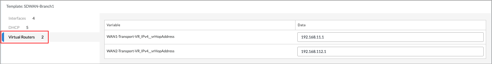
- Click the Post-Staging Template tab, then enter the IPv4 prefix of the interface to use.
- Click the Virtual Routers tab, then IPv4 address of the default gateway to use to connect to the staging Controller node.
- Select the Review tab, review and make any necessary edits, then click Deploy.
- For Releases 21.2.3 and earlier:
- For Releases 22.1.3 and later:
- Select the Bind Data tab and then select the User Input tab. Enter the IPv4 prefix of the interface and the IPv4 address of the default gateway to use to connect to the staging Controller node.
- Click Deploy.

When the activation of the VOS device completes, the Tasks window reports the status.
Use URL-Based ZTP To Activate VOS Devices
With URL-based ZTP, a site administrator activates a VOS device after receiving an email that includes a link to the staging and post-staging Controller node. The administrator connects to the device using a laptop or mobile phone and clicks the link, and then the Controller node completes the device activation. On the Versa Director, you configure the staging Controller node and the contact information for the onsite installer. You can also access the URL from the Director node using REST API calls.
URL-based ZTP decouples a particular hardware device (that is, a particular chassis ID) from a branch location. This means that you can activate any hardware that is running an appropriate version of VOS software. The URL-based ZTP process also allows device activation to be performed using a post-staging Controller node, so you can skip the Versa Networks or provider prestaging process.
You configure URL-based ZTP for a device group.
Before you set up URL-based ZTP, note the following:
- ZTP uses ports 0 and 2 as the WAN ports and ports 1 and 3 as the LAN ports. For CSG700 Series appliances, ZTP uses ports 0 and 1 as the WAN ports and ports 2 and 3 as the LAN ports.
- To use URL-based ZTP on a bare-metal device, run the default configuration script.
- To use URL-based ZTP on a virtual machine (V), load the default-device.cfg file.
- By default, the VOS device runs a DHCP server on its LAN port.
Configure URL-Based ZTP
To create a device group that includes a URL-based ZTP configuration:
- In Director view, select the Workflows tab in the top menu bar.
- Select Devices > Devices in the left menu bar.
- Click the Add icon.
For Releases 22.1.3 and later, the following screen displays with step 1, Basic, selected by default.

For Releases 21.2.3 and earlier, the Add Device popup window displays.
-
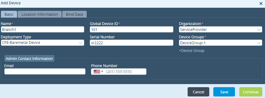
Select the Basic tab, and enter information for the following fields.
Field Description Name (Required) Enter a name for the device.
Value: Text string from 1 through 127 characters
Default: NoneGlobal Device ID (Required) Enter the identifier of the device. This value is populated automatically with the next available number. You can change it to a different available value from 1 through 31. Organization (Required) Select the organization to which this device belongs. Deployment Type (Required) Select the type of deployment:
- CPE-Bare-metal Device
- CPE-Public Cloud
Serial Number Enter the chassis number of the VOS device. This value must be unique. For Releases 22.1.3 and later, you can click Generate Serial Number to automatically generate a serial number. Device Groups (Required) Select the device group to which the device belongs. For the purposes of this procedure, click +Device Group (for Releases 21.2.3 and earlier; for Releases 22.1.3 and later, click + Add New in the Device Group field) and create a new device group, as described in the next step. Admin Contact Information (Group of Fields) Enter information about the administrator for the VOS device. Enter the email address of the administrator associated with the device. - Phone Number
Enter the phone number of the administrator associated with the device. -
Click +Device Group.
For Release 22.1.3 and later, the Add Device Group screen displays:
For Releases 21.2.3 and earlier, the Create Device Group popup window displays:


-
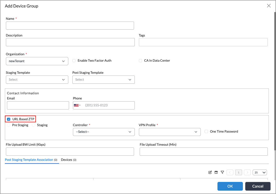
Select URL-Based ZTP and configure the parameters to enable URL-based ZTP. Enter information for the following fields.
Field Description URL-Based ZTP Click to enable URL-based ZTP. Prestaging Click to enable URL-based ZTP during the prestaging state. Staging Click to enable URL-based ZTP during the staging state. Controller Select the Controller node to use as the staging and post-staging Controller node to activate the VOS devices. A link to this Controller node is sent in email to the site installer.
If you upgraded the Director and Controller nodes that were present before the upgrade and they are not listed, check the Controller node status:
- Log in to the Director shell, and enter the following commands:
Admininstrator@Director> cli
Admininstrator@Director> config
Admininstrator@Director% set provider appliances appliance controller-uuid staging-controller
- If the staging-controller value is false for a Controller node that should display in the URL ZTP Controller node list, set the value to true:
Admininstrator@Director% set show provider appliances appliance controller-uuid staging-controller true
- Repeat Step 2 for each Controller node that should display in the list.
- Commit the changes:
Admininstrator@Director% commit
Note: The Controller node either must belong to an organization to which the tenant user has access or must be associated with at least one organization that belongs to the device group's organization or parent organization.
VPN Profile Select the IPsec VPN tunnel to use to reach the staging and post-staging Controller node. In the VPN profile, you define whether the IKE connection between the Controller node and the VOS device uses preshared keys (PSK) or public key infrastructure (PKI).
If no VPN profile displays in the list for the selected Controller node, do the following:
- Log in to the Director shell, and enter the following commands:
Admininstrator@Director> cli
Admininstrator@Director> config
-
Display the provider organization of the selected Controller node:
Admininstrator@Director% show devices device SDWAN-Controller1 config system sd-wan site provider-org
- Based on the name of the Controller organization displayed in the output of Step 2, display a list all VPN profiles:
Admininstrator@Director% show devices device controller-name SDWAN-Controller1 config orgs
org-services controller-org-from-previous-step ipsec vpn-profile vpn-type controller-staging-sdwan
- If the output of the show devices command in Step 3 does not display any VPN profiles, contact Versa Networks Customer Support.
One-Time Password Select to create a password to use only during the URL-based ZTP process. - Click OK.
Edit ZTP URL Parameters
After you have deployed a VOS device, you can edit the parameters related to URL-based ZTP:
- In Director view, select the Administrator tab in the top menu bar.
- Select Inventory > Hardware in the left menu bar.
- Select a VOS device from the main pane. The Edit Hardware popup window displays.
For Releases 22.1.3 and later:
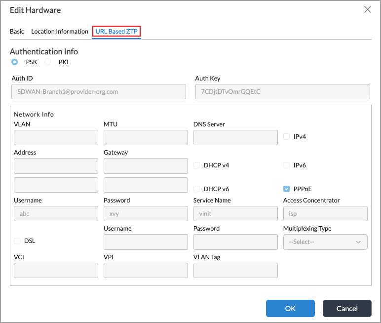
For Releases 21.2.3 and earlier:

- Select the URL-Based TCP tab, and make the desired changes.
- Click OK.
Access the ZTP URL To Activate a VOS Device
To access the URL to use for ZTP, use one of the following options:
- Connect from the AMQP server that you configured on Versa Director. Note that after you onboard and deploy the VOS device, the URL is posted to the AMQP server.
- Query the URL using the following RESTful API call, where x.x.x.x is the IP address of your Versa Director. For example:
http://x.x.x.x:9182/vnms/sdwan/device-url-mappings/device-url-mapping/Branch2
- Copy the URL from the Versa Director Administration > Inventory > Hardware window. On this window, select a VOS device and click the
 URL-Based ZTP Info icon:

Activate a VOS Device Using URL-based ZTP
To activate a VOS device using URL-based ZTP:
- Ensure that ICMP is allowed on the VOS device's WAN ports. ICMP is required because, as part of the activation process, the VOS device sends ICMP probes to the Controller node's WAN port to ensure network reachability.
- If WiFi is enabled on the VOS device, connect to the device from an iPhone or Android device, and skip to Step 4.
- Otherwise, connect a laptop to the LAN port 2 on the VOS device.
- Connect the device to the internet:
- To connect an SD-WAN device, connect WAN port labeled 0 to the internet.

- To connect an SD-LAN device, use the ports indicated for your switch:
(For Releases 22.1.4 and later.) CSX2200 switches—The default WAN ports for ZTP are enet-0/0 WAN-0 (1G) and enet-0/1 WAN-1 (1G). For multigig speeds, you can select enet-0/24 WAN-2 (10G), enet-0/25 WAN-3 (10G), enet-0/28 WAN-4 (10G), or enet-0/29 WAN-5 (10G), as shown below.

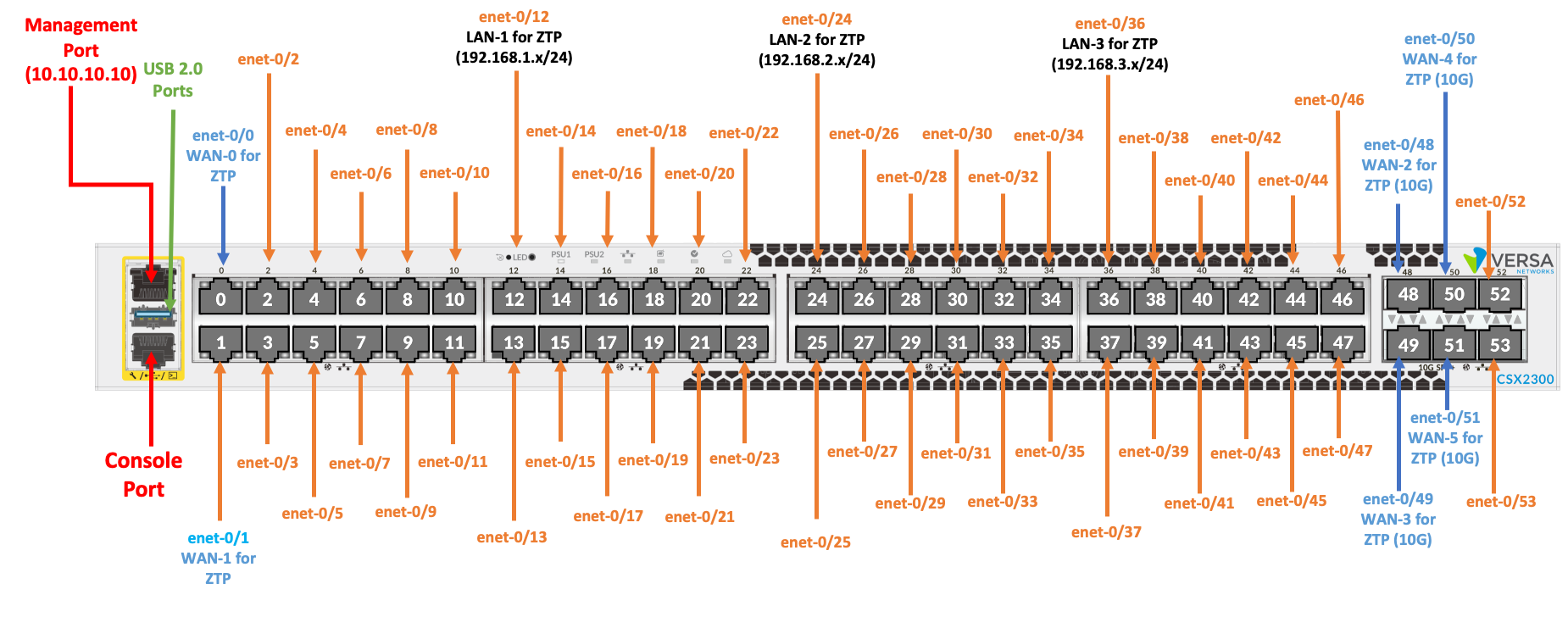
(For Releases 22.1.4 and later.) CSX2300 switches—The default WAN port for ZTP are enet-0/0 WAN-0 (1G) and enet-0/1 WAN-1 (1G)). For multigig speeds, you can select enet-0/48 WAN-2 (10G), enet-0/49 WAN-3 (10G), enet-0/50 WAN-4 (10G), or enet-0/51 WAN-5 (10G), as shown below.
CSX4300 and CSX4500 switches—The default WAN port for ZTP is enet-0/0 WAN-1 (1G). For multigig speeds, you can select enet-0/48 WAN-2 (25G), or enet-0/50 WAN-3 (10G), as shown below.

CSX8300 switches—The default WAN port for ZTP is enet-0/0 WAN-1 (25G). You can also select enet-0/45 WAN-2 (10G) or enet-0/48 WAN-3 (100G), as shown below.

- Click the link in the device activation email that you received. The VOS (FlexVNF) Web-UI screen displays.
- Check the status light in the top menu bar.

If the light is green, proceed to the next step.
If the light is amber, the device configuration was changed and the device no longer has the factory-default settings. As a result, the device might not have been onboarded properly using URL ZTP. To resolve this issue, connect to the device console and issue the following command from the CLI. This command resets the device to the factory-default configuration so that you can use URL-based ZTP and global ZTP.request system load-default - In the Device Management tab, click Start Activation to start the ZTP activation of the VOS device. The VOS device then does the following:
- Check for internet connectivity.
- Fetch valid certificates, and if PKI authentication is selected, check the certificates.
- Connect to the configured staging Controller node and receive its configuration.

- If two-factor authentication is enabled, claim the VOS device:
- When the device boots for the first time, click Claim Device.

- After you claim the device, you receive the device registration code either in an email or as a text message to a mobile phone, depending on the configuration:

- Enter the registration code.

- When the device boots for the first time, click Claim Device.
- When the ZTP process completes, the VOS device reboots.
- On the Director node, verify that the VOS device has been activated.
- If desired, configure static IP addresses and DNS servers in the VOS Web-UI screen. To do this, select the Configuration tab:

Debug URL-Based ZTP
If you are a site administrator, follow these steps to debug URL-based ZTP:
- Ensure that Port 1 is configured as the eth0 interface.
- Ensure that a WAN IP address is configured on Port 2.
- Ensure that the default gateway in the global routing instance is reachable through the WAN port.
- On Port 3, the LAN IP is received via DHCP. Use http://192.168.1.1:80 to access the device or directly use the generated URL.
- Paste the URL in the browser to start the bootstrap process.
You can monitor the progress on Versa Director.
Prepare for a Demo of URL-Based ZTP
If you are showing a demo of URL-based ZTP, follow these steps to set up the VOS device:
- Install a new .bin file on the VOS device. Doing this is not required if you are performing the demo on a newly shipped device.
- Install the factory-default configuration. To do this, run the /opt/versa/scripts/versadevice-factoryreset.sh script on the VOS device. Doing this allows the laptop that you connect to the VOS device to access the internet. Doing this is not required if you are performing the demo on a newly shipped device.
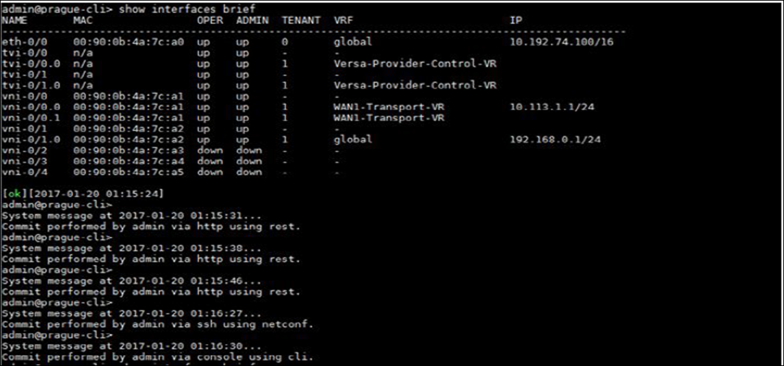
- Check that the interfaces on the VOS device are operational:
admin connected from 10.0.0.27 using ssh on versa-flexvnf
admin@versa-flexvnf-cli> show interfaces brief
NAME       MAC              OPER  ADMIN  TENANT  VRF    IP
---------------------------------------------------------------------------
eth-0/0    00:90:0b:43:10:42  up    up     0    global
vni-0/0    00:90:0b:43:10:43  up    up     -    -
vni-0/0.0  00:90:0b:43:10:43  up    up     1    global  10.0.0.23/16
vni-0/1    00:90:0b:43:10:44  up    up     -    -
vni-0/1.0  00:90:0b:43:10:44  up    up     1    global  192.168.1.1/24
 [ok][2016-08-19 14:50:55]
Use the CLI To Activate VOS Devices
To automatically activate a VOS device from the CLI, run the /opt/versa/scripts/staging.py script.
The following is an example of the options you specify when running the script on an SD-WAN device:
admin@VNF:/$ sudo /opt/versa/scripts/staging.py -l SDWAN-branch@nms-org.com \
-r controller-staging@nms-org.com -c 10.10.10.10 -w 0 -s 10.10.10.20/24 -g 10.10.10.10
This example includes the following options:
- Name of the VOS device to activate (–l SDWAN-branch@nms-org.com)
- Name of the Controller node to authenticate the VOS device (–r controller-staging@nms-org.com)
- IP address of the Controller node (–c 10.10.10.10)
- WAN port to use to reach the internet, here, port 0 (–w 0)
- Static route to configure (–s 10.10.10.20/24)
- Gateway IP address (–g 10.10.10.10)
Specify the –h option to list all available options for this script:
admin@VNF:/$ sudo /opt/versa/scripts/staging.py -h
[sudo] password for admin:
usage: staging.py [-h] [-l LOCAL_ID] [-r REMOTE_ID] [-c CONTROLLER]
[-w {0,1,2,3,...103}] [-v VLAN] [-s STATIC] [-g GATEWAY] [-d]

Setup branch staging configuration

optional arguments:
-h, --help                                                                             Show this help message and exit
-l LOCAL_ID, --local-id LOCAL_ID                                                       Local id-string/email
-r REMOTE_ID, --remote-id REMOTE_ID                                                    Remote id-string/email
-n SERIAL_NUMBER, --serial-number SERIAL_NUMBER                                        Serial number
-c CONTROLLER, --controller CONTROLLER                                                 Controller IPv4 address/FQDN
-c6 CONTROLLER6, --controller6 CONTROLLER6                                             Controller IPv6 address/FQDN
-t {prestaging,staging}, --staging {prestaging,staging}                                Staging type (default=staging)
-wpt {vni,enet}, --wan-port-type {vni,enet}                                            WAN port type [vni | enet] (default=vni)
-w {0,1,2,3,...,103}, --wan-port {0,1,2,3,...,103}                                     WAN port number
-v VLAN, --vlan VLAN                                                                   VLAN ID
-s STATIC, --static STATIC                                                             Static IPv4/mask for WAN link
-s6 STATIC6, --static6 STATIC6                                                         Static IPv6/mask for WAN link
-g GATEWAY, --gateway GATEWAY                                                          Default gateway IP address
-g6 GATEWAY6, --gateway6 GATEWAY6                                                      Default gateway IP address
-d, --dhcp                                                                             Use DHCP for WAN link
-d6, --dhcp6                                                                           Use DHCPv6 for WAN link
-a, --slaac                                                                            Use SLAAC for IPv6 WAN link
-gt GLOBAL_TENANT_ID, --global-tenant-id GLOBAL_TENANT_ID                              Global Tenant id
-lk LOCAL_PSK, --local-psk LOCAL_PSK                                                   IPSec Key (default=1234)
-rk REMOTE_PSK, --remote-psk REMOTE_PSK                                                IPSec Key (default=1234)
-lb LOOPBACK, --loopback LOOPBACK                                                      IPv4/mask for loopback link; used for staging
-dsl, --dsl_intf                                                                       Use DSL interface for staging
-vci DSL_VCI, --dsl_vci DSL_VCI                                                        VCI value, mandatory for DSL
-vpi DSL_VPI, --dsl_vpi DSL_VPI                                                        VPI value, mandatory for DSL
-multiplex DSL_MULTIPLEX, --dsl_multiplex DSL_MULTIPLEX                                Multiplex type, mandatory for DSL; multiplex type can either be llc or vcmux
-vtag DSL_VLAN_TAG, --dsl_vlan_tag DSL_VLAN_TAG                                        VLAN ID for dsl line
-p, --pppoe                                                                            Use PPPoE interface for staging
-pu PPPOE_USER, --pppoe_user PPPOE_USER                                                PPPoE username,; mandatory for PPPoE
-pp PPPOE_PASSWORD, --pppoe-password PPPOE_PASSWORD                                    PPPoE password, mandatory for PPPoE
-ps PPPOE_SERVICE, --pppoe-service PPPOE_SERVICE                                       PPPoE service name
-pa PPPOE_ACCESS_CONCENTRATOR, --pppoe-access-concentrator PPPOE_ACCESS_CONCENTRATOR   PPPoE access_concentrator
-wu WWAN_USER, --wwan_user WWAN_USER                                                   WWAN username
-wp WWAN_PASSWORD, --wwan-password WWAN_PASSWORD                                       WWAN password
-wapn WWAN_APN, --wwan-apn WWAN_APN                                                    WWAN APN name
-wpin WWAN_PIN, --wwan-pin WWAN_PIN                                                    WWAN SIM pin
-lmode {auto,full-duplex,half-duplex}, --link-mode {auto,full-duplex,half-duplex}      Link mode for the interface [auto | half-duplex | full-duplex]
-lspeed {auto,10m,100m,1g,10g,25g,100g}, --link-speed {auto,10m,100m,1g,10g,25g,100g}  Link speed for the interface [auto |10m |100m |1g |10g |25g |100g]
-lfec {fec74,fec91,fec108,auto,none}, --link-fec {fec74,fec91,fec108,auto,none}        Link fec for the enet interface [fec74 | fec91 | fec108 | auto | none]
-t1e1 {0/0,0/1,0/2,0/3}, --t1e1-iface {0/0,0/1,0/2,0/3}                                Use T1E1 interface for staging [0/0 | 0/1 | 0/2 | 0/3 ]
-t1e1-type {t1,e1}, --t1e1-type {t1,e1}                                                T1E1 type (default=t1)
-t1e1-clk-src {internal,external}, --t1e1-clock-source {internal,external}             T1E1 clock source
-encap {ppp,hdlc,frame-relay}, --encapsulation {ppp,hdlc,frame-relay}                  Encapsulation for T1E1 [ppp | hdlc | frame-relay] (default=ppp) ]
-dlci DLCI_NUMBER, --dlci-number DLCI_NUMBER                                           DLCI number for frame-relay encapsulation
-auth {psk,cert}, --auth-type {psk,cert}                                               Authentication type [psk | cert] (default=psk)
-bla BGP_LOCAL_AS, --bgp-local-as BGP_LOCAL_AS                                         BGP local autonomous system number
-bpa BGP_PEER_AS, --bgp-peer-as BGP_PEER_AS                                            BGP peer autonomous system number
-bpi BGP_NEIGHBOR, --bgp-neighbor BGP_NEIGHBOR                                         BGP peer IP address
-pg {0,1,3,5,7,8,10,12,14,15,16,17}, --port-group {0,1,3,5,7,8,10,12,14,15,16,17}      CSX8300 port-group number to change port speed
-pgspeed {4x10G,4x25G}, --port-group-speed {4x10G,4x25G}                               CSX8300 port-group speed values [4x10G] or [4x25G]
[admin@VNF: ~] $
To run the script on an SD-LAN device, you must also include the following options, which are shown in the command below:
admin@VNF:/$ sudo /opt/versa/scripts/staging.py -l SDLAN-branch@nms-org.com -r controller-staging@nms-org.com \
-c 10.10.10.10 -w 0 -wpt enet -s 10.10.10.20/24 -g 10.10.10.10 -pg 0 -pgspeed 4x10G
If you want to use two-factor authentication in the device activation process, enable it as described in Use URL-Based ZTP To Activate a VOS Device, above.
To verify that the VOS device has been deployed, click the Tasks icon in the Versa Director horizontal menu bar. The Tasks window displays.
For Releases 22.1.3 and later:

For Releases 21.2.3 or earlier:

Use a USB Storage Drive To Activate a VOS Device
For Releases 21.2 and later.
If you have physical access to a VOS device, you can stage the SD-WAN CPE device by inserting a USB storage drive into the device. The USB storage drive must contain a file named staging.params, which contains input parameters for the staging.py script. The USB storage drive can optionally contain a VOS package file and certificates. All these files must be at the root (top level) of the USB drive. They cannot be in subdirectories.
When you install the USB storage drive into the VOS device, the device automatically reads the file and configures itself based on the SD-WAN parameters specified in the staging.params file.
The staging.params file contains the parameters required as input for the staging.py script, in a key-value format. The following example shows an example of the minimum configuration required to configure any device:
dhcp
local-id=local@my-company.com
remote-id=remote@remote-site.com
controller=10.1.2.3
To ensure that a specific device is being staged, also include the device's service number in the staging.params file:
serial-number=number
The keywords in the staging.params file directly map to the long-form command-line arguments of the staging.py script, which are shown in Use the CLI To Activate VOS Devices, above. To check the staging.py script options supported in the current version of the VOS software, issue the following command:
$ vsh show-staging-params
In the staging.params file, lines starting with a # are treated as comments and are skipped, and leading spaces are removed. The file can also be in DOS format.
If the USB drive contains a VOS package file (a file whose name has the format versa-flexvnf-xxx-yyy-zzz.bin) or an OS SPack file (a file whose name has the format versa-flexvnf-osspack-xxxxx.bin), these files are copied to the appropriate locations on the VOS device.
Note that to activate a VOS device from a USB drive, the device's configuration must be empty or it must be the factory-default configuration. To delete the configuration from the VOS device, issue the request erase config-file command from the device's CLI. If the VOS device has the factory-default configuration but has not been staged, the activation process automatically stages the device using the configuration information provided in the staging parameters.
Configure VOS Devices and ZTP Automatically Using Cloud-Init
When you instantiate a VOS device in a virtual environment, such as KVM, OpenStack, or a cloud, you can use the cloud-init functionality on the VOS device to automatically onboard the device immediately after you finish installing it. Cloud-init is an industry-standard multidistribution method for cross-platform cloud instance initialization. It is supported across all major public cloud providers, provisioning systems for private cloud infrastructure, and bare-metal installations.
If you do not use cloud-init when you install a VOS device as a VM in the cloud or in a virtualization environment, you must manually configure the VOS device after the installation and then you must perform the staging for ZTP manually. If you use cloud-init, you can pass configuration and staging information to the VOS device, and this information is executed when the device first boots. All three operations—installation, configuration and onboarding—are performed automatically.
The following is an example of a cloud-init file you can use to configure the eth0 interface on a VOS device and to stage the VOS device after it boots. Note that you must retain all the spaces at the beginning of each line for the file to work. YAML is very sensitive to spaces, which serve as an indication of the next action.
#cloud-config
cloud_init_modules:
  - write-files
  - set_hostname
  - update_hostname
  - users-groups
  - ssh

write_files:
  - content: |
      # This file describes the network interfaces available on your system
      # and how to activate them. For more information, see interfaces(5).
      # The loopback network interface
      auto lo
      iface lo inet loopback
      # The primary network interface
      auto eth0
      iface eth0 inet static
       address 192.168.0.230
       netmask 255.255.255.0
       gateway 192.168.0.1
    path: /etc/network/interfaces

  - content: |
      #!/bin/bash
      logger running staging script
      sudo /opt/versa/scripts/staging.py \
          -l SDWAN-Branch@Versa.com \
        -r controller-1-staging@Versa.com \
        -v 0 \
        -d \
        -c 12.23.34.45
    permissions: "0755"
    path: /home/admin/versa.sh

cloud_final_modules:
  - runcmd
  - scripts-user
runcmd:
  - /home/admin/versa.sh
Supported Software Information
Releases 20.2 and later support all content described in this article, except:
- Release 21.2 supports using a USB storage drive to activate a VOS device.
- Release 22.1.3 supports configuring and activating an SD-WAN VOS device to manage Layer 2 access and core switches.
- Releases 22.1.4 and later supports configuring and activating an SD-WAN VOS device to manage secure SD-LAN access and core switches.