CSG300 Series Hardware Guide
At a Glance
The Versa Cloud Services Gateway (CSG) 300 series appliances deliver highly secure site-to-site data connectivity to small businesses and to home offices.
These appliances provide the following features:
- Support for different CPUs and memory sizes:
- Management Ethernet ports with dual use and dedicated options:
- One RJ45 RS-232 console port
- One USB 2.0 management port for plugging in external LTE or WiFi modems
- One copper Gigabit Ethernet dual-purpose port for data and management
- MDI and MDIX autoswitchable copper Gigabit Ethernet ports
- PoE source support on four Ethernet ports, with network interface card (NIC) module add-on
- Wireless options:
- CSG350–Two built-in wireless slots
- CSG355 and CSG365–Two LTE slots and one dedicated built-in wireless slot
- External AC power supply
- Fan for cooling
- Desktop mount, or rack-mountable in a 19” rack (CSG355 and CSG365 only)
CSG300 Appliance Models
The CSG300 appliances are available in the following models:
- CSG350—Compact and optimized appliance for deployment in small branches (up to 75 users) that require advanced application and cloud intelligence with hierarchical QoS and that provide a cost-effective SD-WAN solution. The CSG350 appliances have 32 GB of storage.
- CSG355–Powerful appliance for deployment in both small- and medium-sized branches that require advanced SD-Security (NGFW and UTM) along with comprehensive advanced application and cloud-intelligent SD-WAN services on premises. The CSG355 appliances have 32 GB of storage.
- CSG365—High-performance, powerful appliance for deployment at medium-sized branch locations that require advanced application and cloud-intelligent SD-WAN services and advanced SD-Security (NGFW and UTM. The CSG365 appliances have 64 GB of storage.
Chassis Views
The CSG350 appliance is the smallest of the CSG300 appliances. The CSG355 and CSG365 appliances are physically identical.
CSG350 Appliance
Figure 1 and Figure 2 show the front and rear panels of the CSG350 appliance.
Note: The front panel is the side of the appliance with the SIM slots and two LEDs, for status and power. This is the side that is visible when you install the appliance in an office environment. It also has integrated rack-mount ears for installation in standard 19-inch racks. The rear panel has the power and reset buttons and various connectors and ports.
Figure 1: Front Panel of the CSG350 Appliance

Figure 2: Rear Panel of the CSG350 Appliance

CSG355 and CSG365 Appliances
Figure 3 and Figure 4 show the front and rear panels of the CSG355. The panels for the CSG355 and CSG365 appliances are identical.
Figure 3: Front Panel of the CSG355 Appliance

Figure 4: Rear Panel of the CSG355 Appliance

Front and Rear Panel Components
This article describes the front and rear panel components of a CSG300 series appliance. For the exact location of these components on the appliance, see At a Glance.
Front Panel
The front panel of a CSG300 series appliance has two status LEDs.
LEDs
Table 1 lists the LEDs, their colors and states, and the status they indicate.
Table 1: Front Panel LEDs in a CSG300 Series Appliance
| LED | Color | Status |
|---|---|---|
| Power | Green |
|
| Status | Green, Red |
|
Rear Panel
The rear panel of a CSG300 series appliance has six status LEDs, SIM card slots, and power and reset buttons.
LEDs
The rear panel of a CSG300 series appliance has six LEDs, located in two rows.
Table 2 lists the LEDs, their color and states, and the status they indicate.
Table 2: Rear Panel LEDs in a CSG300 Series Appliance
| LED | Color | Status |
|---|---|---|
| Power | Green |
|
| Status | Green, Red |
|
| Cloud | Green, Red | Currently not supported. |
| Wireless | White |
|
| LTE | White |
|
SIM Card Slots
The rear panel of a CSG300 series appliance has two nano-SIM card slots. If you subscribe to a single wireless service, use the SIM1 slot to install the LTE device. If you subscribe to a dual wireless service, use both the SIM1 and SIM2 slots to activate the LTE devices.
Note: It is strongly recommended that you use only preactivated SIMs in the SIM card slots.
Figure 1: CSG350 Appliance SIM Card Slot Cover

Figure 2: CSG355/CSG365 Appliance SIM Card Slot Cover

To access the SIM card slots on the CSG300 series appliances and to insert a SIM card:
- Remove the SIM card slot cover with Phillips screw, using a screwdriver.
- Insert the SIM card in to the SIM slot as per the orientation shown on the SIM card slot cover.
- If the SIM card is correctly inserted into the SIM slot, it should click into place.
Power Button
The Power button on the rear panel of a CSG300 series appliance turns the power on and off.
To turn the power on, press and immediately release the Power button when the appliance is off.
To turn the power off, press the Power button when the appliance is on, as follows:
- If you press and immediately release the button, the appliance does a graceful software shutdown that is equivalent to issuing the shutdown now command from the operating system shell.
- If you press and hold the button for 10 seconds or more, the power for the appliance turns off and the appliance shuts down.
Reset Button
The Reset button on the rear panel of a CSG300 series appliance resets the appliance. The reset functionality depends on the number of times you press the button within a span of 30 seconds, as described in Table 3. In between each press on the reset button, you must pause for a second to register the key presses.
The Reset button is recessed so that it is not accidentally pressed while the appliance is operational.
To press the Reset button, use a sharp, narrow tool.
Table 3: Reset Button Press Behavior
| Number of Presses |
Behavior |
|---|---|
| 2 | Reset the appliance to the factory-default snapshot. |
| 4 | Reset the appliance to the branch prestaging configuration. |
| 6 | Reset the appliance to the branch staging configuration. |
| 8 | Reset the appliance to branch post-staging configuration. |
You can reset the appliance to the factory-default configuration by issuing the request system reset CLI command.
Reset the Appliance to the Factory-Default Configuration from the CLI
You can reset the appliance to the factory-default configuration from the CLI. You can connect to the appliance through the serial console port or by using SSH.
The factory default reset procedure may take up to 20 minutes to complete. Do not power off the appliance during this time.
To reset an appliance to the factory default configuration:
- To connect to the appliance through the serial console port, see Configure a Management Console to Connect to a CSG300 Series Appliance.
- Log in to the appliance CLI. Please consult Versa technical support for default credentials.
Note: To connect to the appliance using SSH, connect your PC to the management port of the appliance. For the port mapping on the CSG700 series appliance, see Interface Numbering. The management port has the default static IP address 10.10.10.10/24. Configure the PC IP address to any IP from this segment, for example, 10.10.10.1/24. Open an SSH session to the appliance using its IP address, 10.10.10.10.
- Issue the following commands to reset the configuration to factory default. If the current software version on the appliance is the same as that of the factory reset snapshot, the procedure takes about 10 minutes to complete. If the software versions are different, the procedure takes about 20 minutes to complete. Do not power off the appliance during the process.
$ cli
> request system reset
- Verify that all Versa services are running by issuing the vsh status command from the Linux shell The following is a sample output of this command. If all the services are shown as stopped, issue the vsh start command from the Linux shell to start them manually.
$ vsh status
versa-service    is Running, [*] process 6784
versa-infmgr     is Running, [-] process 5623
versa-rfd        is Running, [-] process 5838
versa-vmod       is Running, [-] process 5839
versa-ip2user    is Running, [-] process 5844
versa-imgr       is Running, [-] process 5848
versa-acctmgrd   is Running, [-] process 5845
versa-fltrmgr    is Running, [-] process 5648
versa-vstated    is Running, [-] process 5625
versa-addrmgrd   is Running, [-] process 5857
versa-rt-cli-xfm is Running, [-] process 5798
versa-rtd        is Running, [-] process 5827
versa-dhcpd      is Running, [-] process 5620
versa-eventd     is Running, [-] process 5843
versa-vrrpd      is Running, [-] process 5643
versa-dnsd       is Running, [-] process 5646
versa-ppmd       is Running, [-] process 5793
versa-snmp-xform is Running, [-] process 5800
versa-certd      is Running, [-] process 5849
versa-ntpd       is Running, [*] process 5612
versa-dhclient6  is Running, [-] process 5807
versa-redis      is Running,[-] process 6927
versa-av-redis   is Running, [-] process 5003
versa-spackmgr   is Running, [-] process 5832
versa-monit      is Running, [*] process 6078
versa-confd      is Running, [*] process 4798
versa-fail2ban   is Running, [*] process 6093
versa-auditd     is Running, [*] process 6116
versa-nodejs     is Running, [-] process 5775
- Power off the appliance.
Additional Information
Interface Numbering
Figure 1 shows the mapping of the Ethernet ports to virtual network interface (VNI) numbering for the CSG350 appliance.
Figure 1: CSG350 Port-to-VNI Mapping

Figure 2 shows port-to-VNI mapping for the CSG355 and CSG365 appliances. Note that the CSG355 and CSG365 chassis are identical.
Figure 2: CSG355 and CSG365 Port-to-VNI Mapping

Installation Guidelines
This article provides general safety standards and warnings relating to installing or connecting a CSG300 series appliance.
General Safety Guidelines
Caution: Before installing or removing a CSG300 series appliance, ensure that the appliance chassis is electrically connected to ground. When you are installing or removing an appliance, ensure that you wear an ESD grounding wrist strap. To put the ESD grounding strap on properly, attach it to an ESD point and then place the other end of the strap around your bare wrist, making good skin contact. Failure to use an ESD grounding strap could damage the appliance.
- Install the CSG300 series appliance in compliance with the following local, national, and international electrical codes:
- United States—National Fire Protection Association (NFPA 70), United States National Electrical Code.
- Other countries—International Electromechanical Commission (IEC) 60364, Part 1 through Part 7.
- Evaluated to the TN power system.
- Canada—Canadian Electrical Code, Part 1, CSA C22.1.
- Locate the emergency power-off switch in the installation area. In case of an electrical accident, turn off the power quickly.
- Disconnect power to the appliance before installing or removing it.
- Disconnect power from the circuit that is being used for the appliance.
- If hazardous conditions exist, do not work alone.
- If you are working under conditions that might be hazardous to the eyes, wear safety glasses or goggles.
Caution: There is a risk of explosion if the battery is replaced by an incorrect type.
Federal Communication Commission Interference Statement
This device complies with Part 15 of the FCC Rules. Operation is subject to the following two conditions: (1) This device may not cause harmful interference, and (2) this device must accept any interference received, including interference that may cause undesired operation.
This equipment has been tested and found to comply with the limits for a Class A digital device, pursuant to part 15 of the FCC Rules. These limits are designed to provide reasonable protection against harmful interference when the equipment is operated in a commercial environment. This equipment generates, uses, and can radiate radio frequency energy and, if not installed and used in accordance with the instruction manual, may cause harmful interference to radio communications. Operation of this equipment in a residential area is likely to cause harmful interference in which case the user will be required to correct the interference at his own expense.
If this equipment does cause harmful interference to radio or television reception, which can be determined by turning the equipment off and on, the user is encouraged to try to correct the interference by one of the following measures:
- Reorient or relocate the receiving antenna.
- Increase the separation between the equipment and receiver.
- Connect the equipment into an outlet on a circuit different from that to which the receiver is connected.
- Consult the dealer or an experienced radio/TV technician for help.
FCC Caution: Any changes or modifications not expressly approved by the party responsible for compliance could void the user's authority to operate this equipment.
This transmitter must not be collocated or operating in conjunction with any other antenna or transmitter.
Radiation Exposure Statement
This equipment complies with CE and FCC radiation exposure limits set forth for an uncontrolled environment. This equipment should be installed and operated with minimum distance 20 cm between the radiator and your body.
Warning: Operation of this equipment in a residential environment could cause radio interference.
Warning: Operation of this equipment is for indoor use only.
ANATEL Interference Statement
The following ANATEL interference information applies to Brazil:
Este equipamento não tem direito à proteção contra interferência prejudicial e não pode causar interferência em sistemas devidamente autorizados. Para maiores informações, consulte o site da ANATEL – www.anatel.gov.br.
Declaration of Conformity
The following statement applies to Ukraine:
справжнім (найменування виробника) заявляє, що тип радіообладнання (позначення типу радіообладнання) відповідає Технічному регламенту радіообладнання;
повний текст декларації про відповідність доступний на веб-сайті за такою адресою www.versa-networks.com.
IC Wireless Interference Statement for Canada
The following IC wireless interference information applies to Canada only:
This series appliance contains licence-exempt transmitters or receivers)that comply with Innovation, Science, and Economic Development Canada’s licence-exempt RSSs. Operation is subject to the following conditions:
- This device may not cause interference.
- This device must accept any interference, including interference that may cause undesired operation of the device.
L’émetteur/récepteur exempt de licence contenu dans le présent appareil est conforme aux CNR d’Innovation, Sciences et Développement économique Canada applicables aux appareils radio exempts de licence. L’exploitation est autorisée aux deux conditions suivantes:
- L’appareil ne doit pas produire de brouillage.
- L’appareil doit accepter tout brouillage radioélectrique subi, même si le brouillage estsusceptible d’en compromettre le fonctionnement.
To satisfy RF exposure requirements, a separation distance of 20 cm or more must be maintained between the antenna of CSG300 series device and persons during device operation. To ensure compliance, operations at closer than this distance is not recommended.
Les antennes installées doivent être situées de facon à ce que la population ne puisse y être exposée à une distance de moin de 20 cm. Installer les antennes de facon à ce que le personnel ne puisse approcher à 20 cm ou moins de la position centrale de l’ antenne.
These radio transmitters IC:2417C-EM7455 and 26338-CSGW1 have been approved by Innovation, Science, and Economic Development Canada to operate with the antenna types listed below with the maximum permissible gain indicated. Antenna types not included in this list that have a gain greater than the maximum gain indicated for any type listed are strictly prohibited for use with this device.
- LTE EM7455 modules—Radio transmitter IC: 2417C-EM7455
- Gain of antenna: 3.23 dBi maximum
- Type of antenna: 50 ohm, Dipole
- WiFi CSG-W1 modules—Radio transmitter IC: 26338-CSGW1
- Gain of antenna: 4.55 dBi maximum
- Type of antenna: 50 ohm, Dipole
Le présent émetteur radio IC:2417C-EM7455 and 26338-CSGW1 a été approuvé par Innovation, Sciences et Développement économique Canada pour fonctionner avec les types d'antenne énumérés ci-dessous et ayant un gain admissible maximal. Les types d'antenne non inclus dans cette liste, et dont le gain est supérieur au gain maximal indiqué pour tout type figurant sur la liste, sont strictement interdits pour l'exploitation de l'émetteur.
- LTE EM7455 modules—Radio émetteur IC:2417C-EM7455
- Gain d'antenne: 3.23 dBi maximal
- Type d'antenne: 50 ohm, Dipole
- WiFi CSG-W1 modules—Radio émetteur IC:26338-CSGW1
- Gain d'antenne: 4.55 dBi maximal
- Type d'antenne: 50 ohm, Dipole
- The device for operation in the band 5150-5250 MHz is only for indoor use to reduce the potential for harmful interference to co-channel mobile satellite systems.
Les dispositifs fonctionnant dans la bande de 5 150 à 5 250 MHz sont réservés uniquement pour une utilisation à l'intérieur afin de réduire les risques de brouillage préjudiciable aux systèmes de satellites mobiles utilisant les mêmes canaux. - For devices with detachable antennas, the maximum antenna gain permitted for devices in the bands 5250-5350 MHz and 5470-5725 MHz must be such that the equipment still complies with the EIRP limit.
Pour les dispositifs munis d’antennes amovibles, le gain maximal d'antenne permis pour les dispositifs utilisant les bandes de 5 250 à 5 350 MHz et de 5 470 à 5 725 MHz doit être conforme à la limite de la p.i.r.e. - For devices with detachable antennas, the maximum antenna gain permitted for devices in the band 5725-5850 MHz must be such that the equipment still complies with the EIRP limits as appropriate.
Pour les dispositifs munis d’antennes amovibles, le gain maximal d'antenne permis (pour les dispositifs utilisant la bande de 5 725 à 5 850 MHz) doit être conforme à la limite de la p.i.r.e. spécifiée pour l'exploitation point à point et l’exploitation non point à point, selonle cas. - Where applicable, antenna types, antenna models) and worst case tilt angles necessary to remain compliant with the EIRP elevation mask requirement set forth in section 6.2.2.3 must be clearly indicated.
Lorsqu’il y a lieu, les types d’antennes (s’il y en a plusieurs), les numéros de modèle de l’antenne et les pires angles d’inclinaison nécessaires pour rester conforme à l’exigence de la p.i.r.e. applicable au masque d’élévation, énoncée à la section 6.2.2.3, doivent être clairement indiqués.
VCCI Interference Statement for Japan
This is a Class A product based on the standard of the VCCI Council. If this equipment is used in a domestic environment, radio interference may occur, in which case, the user may be required to take corrective actions.
この装置は、クラスA情報技術装置です。この装置を家庭環境で使用すると電波妨害を引き起こすことがあります。この場合には使用者が適切な対策を講ずるよう要求されることがあります。 VCCI-A
NBTC Thailand (SDoC) Statement
This telecommunication equipment conforms to the standard or technical requirements of NBTC.
เครื่องโทรคมนาคมและอุปกรณ์นี้ มีความสอดคลอ้ งตามมาตรฐานหรือขอ้ กำหนดทางเทคนิคของ กสทช.
QR Code

Install a CSG300 Series Appliance
This article provides instructions about how to unpack a CSG300 series appliance and how to mount a CSG355 or CSG365 appliance in a 19-inch rack.
Unpack a CSG300 Series Appliance
The CSG300 series appliance is packed in a plastic box, and it is shipped in a cardboard carton, secured with foam packing material. The carton also contains an accessory box. It is recommended that you unpack the appliance only when you are ready to install it.
To unpack a CSG300 series appliance:
- Open the top flaps of the cardboard carton.
- Remove from the box the foam packing material holding the appliance and the accessories in place. See Figure 1.
- Remove the accessory box and the appliance from the foam packing material.
- Remove the accessories from the accessories box.
- Verify the components against the packing list that is included in the box.
Figure 1: Unpack a CSG300 Series Appliance

Note: It is recommended that you save the shipping carton and packing material when unpacking the appliance, in case you need to later move the appliance or return it. See How To Return Hardware.
Packing List for a CSG300 Series Appliance
The cardboard carton in which a CSG300 series appliance is shipped contains a packing list. Check the packing list against the parts that you receive in the shipping carton.
Packing List for the CSG350 Appliance
Table 1 lists the parts shipped with a CSG350 appliance.
Table 1: Parts Shipped with a CSG350 Appliance
| Components | Quantity |
|---|---|
| CSG350 appliance chassis | 1 |
| AC power adapter | 1 |
| Standard 3-prong C13 power cable, minimum 2 Amps (US only) | 1 |
| LTE antenna (included with LTE module only) | 2 for single LTE module 4 for dual LTE module |
Packing List for the CSG355 or CSG365 Appliance
Table 2 lists the parts shipped with a CSG355 or CSG365 appliance.
Table 2: Parts Shipped with a CSG355 or CSG365 Appliance
| Components | Quantity |
|---|---|
| CSG355 or CSG365 appliance chassis | 1 |
| AC power adapter | 1 |
| Standard 3-prong C13 power cable, minimum 2 Amps (US only) | 1 |
| LTE antenna (included with LTE module only) | 2 for single LTE module 4 for dual LTE module |
| WiFi antenna (included with WiFi module only) | 2 |
| Rack-mounting ears | 2 |
| Screws for rack-mounting ears |
6 (size M4) |
| Screws for rack mounting | 4 (size M6) |
Mount a CSG355 or CSG365 Appliance in a Rack
You can mount a CSG355 or CSG365 appliance in a 19-inch rack. Two people are required to mount the appliance.
To mount the appliance, ensure that you have the following tools:
- Number 2 Phillips (+) screwdriver
- Tape measure
To mount a CSG355 or CSG365 appliance in a 19-inch rack:
- Place the appliance chassis on a flat, stable surface.
- Check the internal dimensions of the rack with a tape measure. The appliance is 22 cm wide (about 8.6 inches) and must fit within the mounting posts.
- Attach the two mounting ears to each side of the appliance chassis using a minimum of six M4 screws that are shipped with the appliance. Do not overtighten the screws.
Figure 2: Attach the Mounting Ears to a CSG300 Series Appliance

- Grasp both sides of the appliance chassis, making sure that the front of the chassis is facing you.
- Stand in front of the rack and lift the chassis. Then, gently insert the chassis into the rack and slide it as far back as possible.
Figure 3: Insert a CSG365 Series Appliance into the Rack

- Have a second person secure the mounting ears to the front of the rack using the four M6 screws that shipped with the appliance. Insert and then tighten the screws. Do not overtighten the screws.
Figure 4: Secure the Mounting Ears to the Rack

Connect Earth Ground to a CSG300 Series Appliance (Optional)
CSG300 series appliance provides an optional screw-on point on the unit for deployments that require earth grounding. In such cases, you can use the standard grounding screw with a custom cable as outlined below. The cable can be made onsite as required. You must use barbed washer at both ends to break through painted surfaces to guarantee good electrical contact.
Figure 5: Standard Grounding Screw with Custom Cable

Connect a CSG300 Series Appliance
This article describes how to connect a CSG300 series appliance to an AC power source and to a management console.
Versa recommends an uninterruptible power strategy that prevents power interruptions. A UPS can isolate unpredictable power outages or blackouts, brownouts, lightning, power surges, or spikes.
Step 1: Connect AC Power to a CSG300 Series Appliance
Before you begin connecting AC power to a CSG300 series appliance, ensure that you have:
- Electrostatic discharge (ESD) wrist strap.
- An AC power cord is shipped with the appliances only for U.S. customers. Each power supply has a C14 plug that allows you to plug in standard power cords with C13 termination. The other end of the cord must have appropriate local plug.
To connect a CSG300 series appliance to an AC power source:
- Attach one end of the ESD grounding strap to your bare wrist, and connect the other end to the ESD point on the rack.
- Plug one end of the AC power cord into the AC power adapter.

- Plug the NEMA 5-15 end of the AC power cord into an AC power source outlet.

- Plug the DC end of the power supply unit into the back of the CSG300 series appliance.
Step 2: Configure a Serial Management Console to Connect to a CSG300 Series Appliance
CSG300 series appliances are equipped with an RJ45 serial console port.
To connect to the console port, use an RJ45-to-USB serial console cable:
- Plug the RJ45 end of the console cable into the console port located on the rear panel of the CSG300 series appliance.
- Plug the USB end of the console cable into the management console (that is, the laptop).
To communicate with the appliance, you must have a terminal emulation program, such as PuTTY, running on your system. When you set up the connection, use the following default console port settings:
- Speed (baud): 115200
- Data bits: 8
- Stop bits: 1
- Parity: None
- Flow control: None
To connect a management console to a CSG300 series appliance:
- Open the PuTTY application. The PuTTY configuration window displays.

- In the Category navigation pane, click Session, and then in the Connection Type menu, click Serial.

- In the Category navigation pane, click Connection > Serial. The Options Controlling Local Serial Lines page displays.
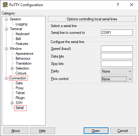
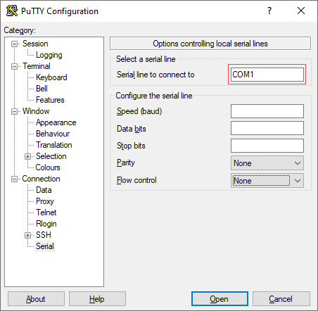
- In the Serial Line To Connect To field, enter the COM port that your device is connected to. The default COM port is COM1.
- In the Configure the Serial Line section, enter the following information.
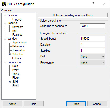
- In the Speed (Baud) field, enter the digital transmission speed. For CSG700 series appliances, the speed must be 115200.
- In the Data bits field, enter the number of data bits used for each character. The recommended value is 8.
- In the Stop bits field, enter the number of bits to be sent at the end of every character. The recommended value is 1.
- In the Parity field, select None. This is the method of detecting errors in transmission.
- In the Flow Control field, select None. This is the method of preventing data overflow.
- Optionally, in the Category navigation pane, click Session, and then in the Saved Sessions field, enter a name to save the session settings.
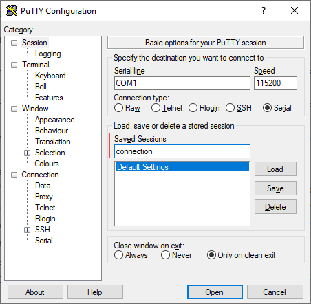
- Click Save.
- To open the session, click Open.

- Log in to the appliance CLI. Please consult Versa technical support for default credentials.

Step 3: Connect a CSG300 Series Appliance to a Network Management Console
You can deploy and manage a CSG300 series appliance from a Director or Concerto node. While you can configure and manage the appliance using a management console, it is recommended that you do so from the Director or Concerto node.
You can perform monitoring and troubleshooting from the CSG300 series appliance's CLI. To access the CLI, connect the appliance to the management console using a cable with an RJ-45 connector. Plug the RJ45 connector into the console port on the CSG300 series appliance, and plug the other end of the cable into the console server or into a management console.