Configure LAN Connections
![]() For supported software information, click here.
For supported software information, click here.
On the Network LAN screen, you can configure LAN profiles, DHCP address pools, static routes, a DNS name server, and port forwarding. You can also reserve an IP address that is assigned by DHCP to a device. You configure these parameters for both Ethernet and WiFi ports.
To restore the default configuration, click Easy Quick Picks. Click the Refresh icon to update information on the screen.
Configure a LAN
- Click Configure in the left menu bar to open the Configure dashboard.
- Hover over the device in the honeycomb, and click Configure to open the site information window.

- Click Next to open the Configuration > Network screen.

- Click the LAN box to open the Network > LAN screen.

- Click to configure the following:
- LAN Profiles
- Ethernet and WiFi Ports
- Port Forwarding
- Device IP Address Reservation

The following sections describe how to configure each of these LAN components.
Configure LAN Profiles
You can configure a LAN profile and use it when you configure Ethernet ports and WiFi interfaces.
To configure a LAN profile:
- Hover over the device in the honeycomb, and then click Configure to open the site information window.
- Click Next to open the Configuration > Network screen.
- Click the LAN box to open the Network > LAN screen.
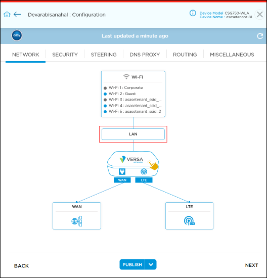
- Click the LAN Profile box to open the Network > LAN > LAN Profiles screen.

For each LAN profile, you configure IRB interfaces (including DHCP, DHCP lease profile, DHCP relay, and DHCP custom options), virtual LANs (Layer 2 and Layer 3 switching), 802.1X RADIUS authentication, and Spanning-Tree Protocol, as described in the following sections.
Configure IRB Interfaces
Integrated routing and bridging (IRB) associates a Layer 3 interface with a Layer 2 bridge domain so that packets can be routed to and from the bridge domain. On IRB interfaces, you can configure all standard Layer 3 interface settings, such as a DHCP server, DHCP relay, and static routing. You can also associate an IRB interface with a VLAN configuration.
To decide whether to route or bridge an incoming packet, a virtual switch uses information in the Layer 2 frame's MAC address. If the destination MAC address in the ingress frame matches the MAC address of one of the IRB interfaces, the packet is routed using that IRB as the ingress interface, and the packet is treated as Layer 3 packet. If the destination MAC address of the ingress frame does not match the MAC address of one of the IRB interfaces, the packet is bridged based on the destination MAC address. Other switches obtain the MAC address of an IRB interface by issuing an Address Resolution Protocol (ARP) request for the associated IP address.
An IRB interface is operationally up when any one of the Layer 2 interfaces associated with the corresponding bridge domain is up. When all the Layer 2 interfaces in a bridge domain are down, the IRB interface is considered to be operationally down.
Virtual routing and forwarding (VRF) is a multisegmented network topology that is part of the organization's VPN. A VRF allows you to configure and maintain more than one instance of the routing and forwarding table in the same router. To configure routing, you must associate a VRF with a specific LAN or WLAN port.
An operator, store admin, MSP, or reseller can enable multi-VRF for organization while creating a new customer. Then, a user can use the option to add VRF when configuring the LAN profile and Ethernet. After the VRF option is enabled for an organization, an administrator cannot disable it using the create or edit organization window. By default, one VRF is created with the name of the organization and all the initial LAN ports are associated with this VRF. You cannot delete the default LAN-VRF after it is created.
To enable the VRF option in the LAN profile configuration, you must first lock the device using the enable lock mode option in the honeycomb view in the Titan Portal > Configure page. The lock icon displays only if the device is deployed. A blue lock icon indicates that the device is unlocked, and a red lock icon indicates that the device is locked. After you publish the changes to Titan Portal, you must unlock the device.
To configure an IRB interface:
- Click Configure in the left menu bar to open the Configure dashboard.
- Hover over the device in the honeycomb, and then click Configure to open the site information window.
- Click Next to open the Configuration > Network screen.
- Click the LAN Profile box to display the IRB tab, and enter information for the following fields.

Field Description IRB Ports (Group of Fields) - IRB Unit
Enter a unit number for the IRB interface. The IRB interface is added to the interface list using this number, and you can use the number to search for a specific IRB interface.
Range: 0 through 127
- MTU
Enter the maximum transmission unit size, in bytes, of the largest protocol data unit that the port can receive or transmit.
Range: 72 through 9000 bytesDefault: 1500 bytes
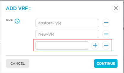
VRF Select the VRF that was added for the organization and device. For multi-VRF, you can add up to 20 VRFs for an organization.
To add a new VRF, click the
 icon. Then, in the Add VRF popup window, enter a VRF name, click the
  icon, and then click Continue. When you add a new VRF, do not use the keyword LAN-VR along with the VRF name.
IP Address - IP Address/Mask (Required)
Enter the IP address and prefix length of the IRB interface. DHCP Server Click to configure DHCP server settings, DHCP lease profiles, and DHCP custom options. For more information, see Configure DHCP Settings, Add a DHCP Lease Profile, and Configure DHCP Custom Options. DHCP Relay Click to configure DHCP relay settings. For more information, see Configure DHCP Relay Settings. Multiple IP Addresses Click to enter multiple IP addresses and subnet masks. The maximum number of IP addresses is 4. Multiple IP addresses and subnet masks are available only with static IP configuration. To use DHCP server or DHCP relay, select the single IP Address/Subnet Mask. - IP Address/Mask (Required)
Enter the IP address and prefix length of the IRB interface and click the
 Add icon. To delete an IP address/mask, click the
  Minus icon.
Bandwidth (Group of Fields) You can configure uplink bandwidth and downlink bandwidth on the LAN interface or per VLAN (subinterface). Values entered in Kbps and Gbps are automatically converted to Mbps. - Uplink Bandwidth
Enter the actual uplink bandwidth purchased from the service provider. The uplink bandwidth is the traffic from the branch to the outside network.
Range:
- In Kbps—1000 through 40000000 Kbps
- In Mbps—1 through 40000 Mbps
- In Gbps—0.001 through 40 Gbps
- Downlink Bandwidth
Enter the actual downlink bandwidth purchased from the service provider. The downlink bandwidth is the traffic from the outside network to the branch.
Range:
- In Kbps—1000 through 40000000 Kbps
- In Mbps—1 through 40000 Mbps
- In Gbps—0.001 through 40 Gbps
Zone Protection (Group of Fields) - Zone Protection
Select a zone protection profile. To associate a zone protection profile to a network, the profile must be pushed to the device, otherwise the configuration fail with an error.
To add a new zone protection profile, click the
 icon. For more information, see Configure Zone Protection Profiles.
- Logging
Click to configure logging:
- None—Click to perform no logging.
- Default—Click to use default logging.
- Custom—Click to configure logging to a customer log server. Based on the rule match, the device may send a large number of log messages.

- Please Select—If you select Custom, click the down arrow to select a log profile.
To create a new custom flow logs profile, click . For more information, see Add Custom Logs Profile.
- Please Select—If you select Custom, click the down arrow to select a log profile.
Configure DHCP Settings
On Titan devices, you can configure a Dynamic Host Configuration Protocol (DHCP) server and a DHCP relay agent. The DHCP server assigns and manages IP addresses from an address pools on the device to DHCP clients. You can configure the DHCP server to assign the IP address of the Domain Name System (DNS) server, the default device, and other parameters. You can also set the IP address of a DHCP server to which the DHCP relay agent forwards client requests.
To configure DHCP settings:
- Hover over the device in the honeycomb, and then click Configure to open the site information window.
- Click Next to open the Configuration > Network screen.
- Click the LAN box to open the Network > LAN screen.
- Click the LAN Profile box to open the Network > LAN > LAN Profiles screen.
- Click the DHCP Server checkbox to activate configuration fields on the screen.
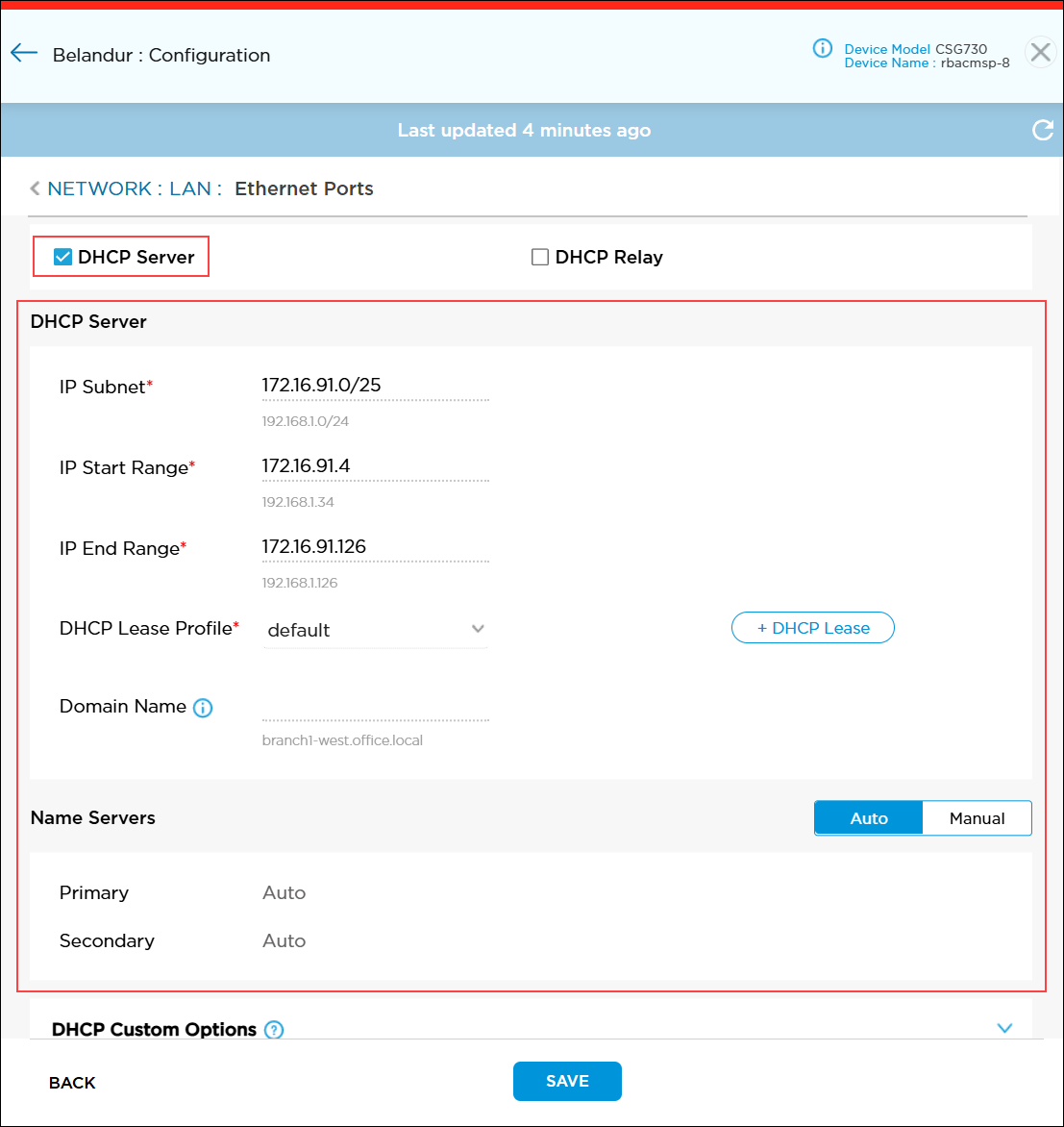
- Enter information for the following fields.
Field Description IP Subnet Enter a valid IP prefix and length. The prefix length must be /25, for example, 172.16.4.0/25. IP Start Range Enter the lowest IP address in the DHCP address pool. IP End Range Enter the highest IP address in the DHCP address pool. DHCP Lease Profile Select the lease profile for the network level. To add a DHCP lease profile, click the
 icon. For more information, see Add a DHCP Lease Profile.
Domain Name For IPv4, enter the name of the domain from which addresses are allocated. Name Servers By default, primary and secondary DNS name servers are configured automatically. To manually configure these servers, click Manual and enter the IP addresses of the primary and secondary DNS name servers. - Click Save to save the settings.
Configure DHCP Relay Settings
- Hover over the device in the honeycomb, and click Configure to open the site information window.
- Click Next to open the Configuration > Network screen.
- Click the LAN box to open the Network > LAN screen.
- Click the LAN Profile box to open the Network > LAN > LAN Profiles screen.
- Click the DHCP Relay checkbox.
- Enter the IP address of the DHCP relay agent. To enter multiple IP addresses, separate them by a comma.

Add a DHCP Lease Profile
A DHCP lease profile specifies the duration and properties of the lease profile.
To add a DHCP lease profile:
- In the Network > LAN > LAN Profiles window, click the DHCP Server field to activate configuration fields on the screen.
- Click the
 icon. In the DHCP Lease Profile popup window, enter information for the following fields.

Field Description Lease Profile Name (Required) Enter a name for the lease profile. The name cannot include any spaces. Description Enter a text description for the lease profile. Life Time Enter how long the lease profile is valid.
Range: 60 through 31536000 seconds
Default: 11600 seconds
Renew Timer Enter the time during which a client can renew the lease profile. You can configure the renew timer to be less than or equal to 50 percent of the valid lifetime.
Range: 60 through 31536000 seconds
Default: 10000 seconds
Rebind Timer Enter the time during which a rebind request can be sent by a client after a period of inactivity. You can configure the rebind timer to be less than or equal to 80 percent of the valid lifetime.
Range: 60 through 31536000 seconds
Default: 20001 seconds
- Click Add. The lease profile displays.
- Click the Trash icon to delete a profile. Note that you cannot edit a lease profile.
- Click Continue.
Configure Custom DHCP Options
For Titan sites, you can configure custom DHCP options on LAN interfaces and on VLANs. All types of LAN interfaces, including Ethernet, VLAN, Aggregated Ethernet, and IRB, support custom DHCP options. You can configure DHCP Options 42, 43, and 66. You can configure the options using the following types of values: Boolean, fully qualified domain name (FQDN), hexadecimal string, IPv4 address, and string.
To configure custom DHCP options:
- In the Network > LAN > LAN Profiles window, click DHCP Custom Options to open the DHCP Custom Options pane.

- Enter information for the following fields.
Field Description Vendor ID Click if vendor information is exchanged between the DHCP server and the client. Default Click to make this custom DHCP option the default. Vendor ID (Required) When a DHCP client represents multiple vendors, enter the vendor ID for DHCP. This field is applicable for vendor ID option. You cannot edit the vendor ID after it has been configured.
Code Enter the DHCP option code to use for default option:
- 42—NTP server
- 43—Vendor-specific
- 66—TFTP server
Type Select the DHCP option data type:
- Boolean
- FQDN
- Hexadecimal string
- IPv4 address
- String
Array Click to use an array to enter multiple DHCP custom option values in all DHCP messages. Persistent Click to include the custom DHCP option in all DHCP messages. Value Enter a value for the option code. If you select Array, click the list in the Value fields to add multiple options. For example, if the data type value is IPv4 Address:
- Click Add IPv4 Address.

- In the Add Multiple DHCP Options popup window, enter the IP address. To enter multiple IP addresses, click the
 Add icon.

- Click Continue.

- Click + DHCP Option to save the option to the DHCP screen. The new option displays on the screen.

- Click the Trash icon to delete a DHCP option.
- Click Save to save the changes to the Titan cloud before leaving the LAN Profiles screen.
Configure Virtual LANs (Layer 2 and Layer 3 Switching)
VLANs are used to enhance performance by reducing the need to send broadcast and multicast packets to unnecessary destinations. VLANs also ease network configuration by logically connecting devices without the need to physically relocating those devices. Note that after you add a VLAN configuration, you cannot change it. However, you can change the static IP address at any time.
To configure VLAN:
- Click Configure in the left menu bar to open the Configure dashboard.
- Hover over the device in the honeycomb, and click Configure to open the site information window.
- Click Next to open the Configuration > Network screen.
- Click the LAN Profile box, and then select the VLAN tab.

- Enter information for the following fields.
Field Description Port Type Select the port type:
- Routed (Layer 3)
- Switched (Layer 2)
Routed (Layer 3) - VLAN Name (Required)
Enter a name for the virtual LAN. - VLAN ID (Required)
Enter the virtual LAN ID.
Range: 0 through 4094
- MTU
Enter the maximum transmission unit size, in bytes, of the largest protocol data unit that the port can receive or transmit.
Range: 72 through 9000 bytes
Default: 1500 bytes
- VRF
Click the VRF list, and then select a VRF. To configure routing, the VRF must be associated with a specific LAN or WAN port.
To add a new VRF, click the
 icon. In the Add VRF popup window, enter a VRF name, click the
  icon, and then click Continue. When you add a new VRF, do not use the keyword LAN-VR along with the VRF name.

IP Address - IP Address/Mask (Required)
Enter the IP address and prefix length. The prefix length must be /25. DHCP Server
Click to configure DHCP server settings, DHCP lease profiles, and DHCP custom options. For more information, see Configure DHCP Settings, Add a DHCP Lease Profile, and Configure DHCP Custom Options. DHCP Relay
Click to configure DHCP relay settings. For more information, see Configure DHCP Relay Settings. Multiple IP Addresses Click to enter multiple IP addresses and subnet masks. The maximum number of IP addresses allowed is 4. Multiple IP addresses and subnet masks are available only with static IP configuration. To use DHCP server or DHCP relay, select the single IP Address/Subnet Mask. - IP Address/Mask (Required)
Enter the IP address and prefix length of the VLAN interface and click the
 Add icon. To delete an IP address/mask, click the
  Minus icon.
Bandwidth (Group of Fields) You can configure uplink bandwidth and downlink bandwidth on the LAN interface or per VLAN (subinterface). Values entered in Kbps and Gbps are automatically converted to Mbps. - Uplink Bandwidth
Enter the actual uplink bandwidth purchased from the service provider. The uplink bandwidth is the traffic from the branch to the outside network.
Range:
- In Kbps—1000 through 40000000 Kbps
- In Mbps—1 through 40000 Mbps
- In Gbps—0.001 through 40 Gbps
- Downlink Bandwidth
Enter the actual downlink bandwidth purchased from the service provider. The downlink bandwidth is the traffic from the outside network to the branch.
Range:
- In Kbps—1000 through 40000000
- Kbps In Mbps—1 through 40000 Mbps
- In Gbps—0.001 through 40 Gbps
Zone Protection (Group of Fields) - Zone Protection
Select a zone protection profile. To associate a zone protection profile to a network, the profile must be pushed to the device, otherwise the configuration fails with an error.
To add a new zone protection profile, click the
 icon. For more information, see Configure Zone Protection Profiles.
- Logging
Click to configure logging:
- None—Click to perform no logging.
- Default—Click to use default logging.
- Custom—Click to configure logging to a customer log server. Based on the rule match, the device may send a large number of log messages.

- Please Select—If you select Custom, click the down arrow to select a log profile.
To create a new custom flow logs profile, click . For more information, see Add Custom Logs Profile.
- Please Select—If you select Custom, click the down arrow to select a log profile.
Switched (Layer 2) - VLAN ID (Required)
Enter the virtual LAN ID.
Range: 0 through 4094
- IRB
Select an IRB interface to associate a Layer 3 interface with a Layer 2 bridge domain. To create an IRB interface, see Configure IRB Interfaces. -
Click the
 icon. The VLAN is displayed with the VLAN ID in the VLAN Tags section.
 -
Click Save.
Configure 802.1X Device Authentication
IEEE 802.1X is a port-based network access control (PNAC) protocol that authenticates devices before they can connect to the network and gain access to network resources. You can configure 802.1X to prevent unauthorized network devices from accessing the network and to allow known devices to connect to the network without requiring authentication. You configure 802.1X on a VNI interface.
When you configure a VNI interface to be an authenticator, a RADIUS server can authenticate each user or device connected to a port before that user or device can access any network services. RADIUS is a distributed client-server system that secures networks against unauthorized access. A RADIUS server provides an external database that you can use to authenticate users before allowing them to access a network, a device, or related services. To configure a RADIUS server, see Configure a RADIUS Server.
To configure 802.1X device authentication, you do the following:
- If you are using RADIUS as the 802.1X authentication server, you must configure the RADIUS server.
- Configure an 802.1X authentication profile. If you are using external RADIUS authentication, define the information that the authenticator uses to communicate with the RADIUS server. For more information, see Configure an 802.1X Authentication Profile.
- To enable authentication on a specific interface, configure the interfaces for 802.1X authentication to control.
Configure 802.1X Device Authentication
- Hover over the device in the honeycomb, and click Configure to open the site information window.
- Click Next to open the Configuration > Network screen.
- Click the LAN box to open the Network > LAN screen.
- Click the LAN Profile box to open the Network > LAN > LAN Profiles screen.
- Click the 802.1X tab and enter information for the following fields.
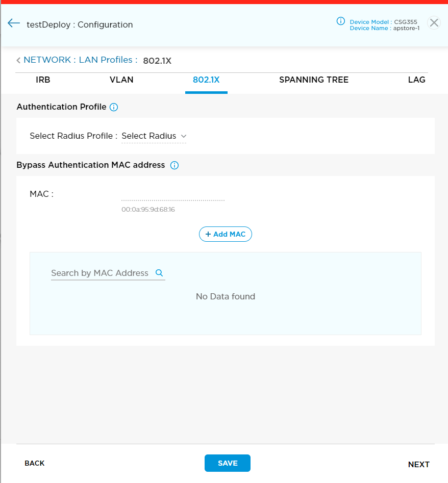
Field Description Authentication Profile - Select RADIUS Profile
Click and select a RADIUS profile from the popup window, and then click Continue. For more information, see Configure an 802.1X Authentication Profile.

Bypass Authentication MAC Address - MAC
Enter the MAC address of a device that is allowed to bypass the 802.1X authentication process. - Click the
 icon, and then click Save.
Configure an 802.1X Authentication Profile
If you are using external RADIUS authentication, configure a RADIUS profile to define the information that the authenticator uses to communicate with the RADIUS server.
To configure an 802.1X authentication profile:
- In the Select RADIUS Profile field, click the RADIUS Profile list.
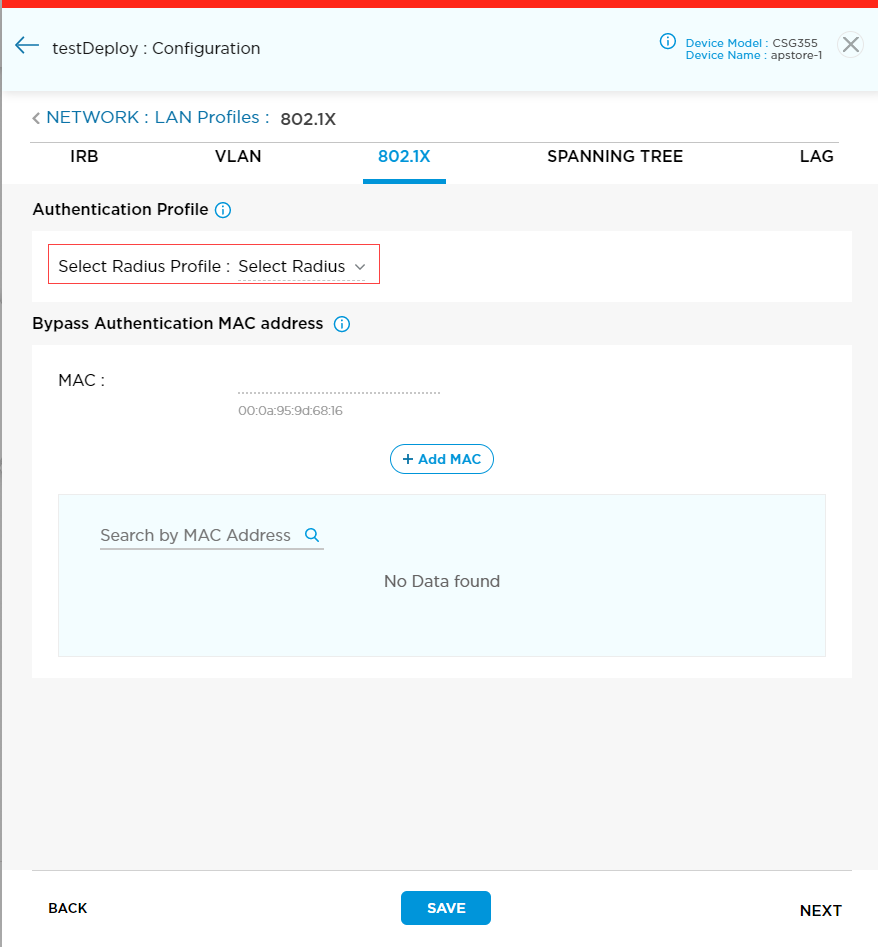
- In the popup window, click the
 icon.
icon.

- In the Add RADIUS Profile popup window, enter information for the following fields.
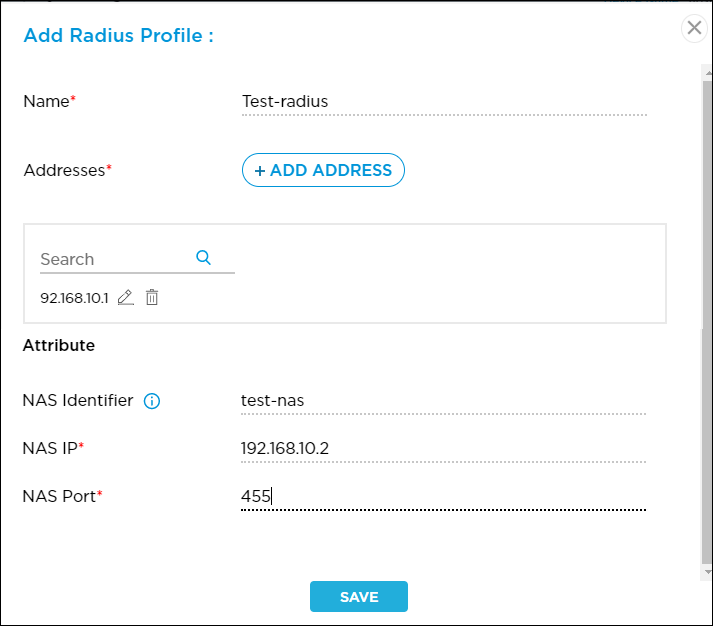
Field Description Name (Required) Enter a name for the 802.1X authentication profile. Addresses (Required) Click the  icon to enter the IP address and other details of the RADIUS server. To configure a RADIUS server, see Configure a RADIUS Server.
Attribute - NAS Identifier
Enter a text string to identify the network access server (NAS) that originates the access request. - NAS IP (Required)
Enter the IP address of the NAS that is requesting authentication. - NAS Port (Required)
Enter the number of the physical port to use to connect to the NAS that is authenticating the user.
Range: 0 through 65535
Default: None
-
Click Save.
Configure a RADIUS Server
If you are using RADIUS as the 802.1X authentication server, configure the RADIUS server:
- In the Select RADIUS Profile field, click the RADIUS Profile list.

- In the popup window, click the
 icon.
icon.

- In the Add RADIUS Profile popup window, click the icon

- In the Addresses popup window, enter information for the following fields.

Field Description IP Address (Required) Enter the IP address of the RADIUS server. Port (Required) Enter the number of the listening port on the RADIUS server. This is the port number to communicate with the RADIUS directory service.
Range: 0 through 65535
Default: None
Shared Secret (Required) Enter a password that the Titan device uses to access the RADIUS server. Routing Instance Select the routing instance to use to communicate with the RADIUS server. - Click Add, and then click Save.
Configure Spanning-Tree Protocol
The Spanning-Tree Protocol (STP) is a network protocol that builds a loop-free logical topology for Ethernet networks. You can configure Rapid Spanning-Tree Protocol (RSTP) or Multiple Spanning-Tree Protocol (MSTP). The STP, RSTP, and MSTP protocols are supported on switching interfaces.
RSTP enables fast spanning-tree reconvergence by simplifying the port states and changing the way ports transition from one state to another. RSTP is backward-compatible with the STP. You can choose to run the RSTP state machine in STP mode.
You configure RSTP in a routing instance, either in a Layer 2 control routing instance or a virtual switch routing instance. When you configure RSTP in a Layer 2 control routing instance, the interface state of a port as determined by the RSTP is associated with all the bridge domain interfaces on the port across all the routing instances. When you configure RSTP in a virtual switch routing instance, all bridge domain interfaces corresponding to that port should be present in the virtual switch only.
MSTP supports one Common Internal Spanning Tree (CIST) and 64 multiple spanning-tree instances (MSTIs). MSTP is an extension of the STP and RSTP that enables the use of alternate spanning trees for different VLANs or groups of VLANs. Using alternate spanning trees can result in alternate paths being utilized more effectively. You can group VLANs into a single MSTI. If a VLAN is not part of any MSTI, it belongs to the CIST. Layer 2 packets follow the MSTI/CIST topology corresponding to the VLAN.
You configure MSTP in a routing instance, either in a Layer 2 control routing instance or a virtual switch routing instance. When you configure MSTP in a Layer 2 control routing instance, the protocol state determined by MSTP is associated with all bridge domain interfaces on a port across all routing instances. When you configure MSTP in a virtual switch routing instance, all bridge domain interfaces corresponding to a port must be present in the virtual switch only.
Configure RSTP
- Hover over the device in the honeycomb, and click Configure to open the site information window.
- Click Next to open the Configuration > Network screen.
- Click the LAN box to open the Network > LAN screen.
- Click the LAN Profile box to open the Network > LAN > LAN Profiles screen.
- Select the Spanning Tree tab and enter information for the following fields.

Field Description Spanning Tree Click the toggle key to enable or disable STP. RSTP Click to configure RSTP parameters. Bridge Priority Enter the RSTP bridge priority value to use to determine which device in the spanning tree is the root bridge. A lower bridge priority value configures a higher priority.
Range: 0 through 61440 (must be a multiple of 4096)
Default: 32768Forward Delay Enter how long an interface remains in the listening and learning states, in seconds.
Range: 4 through 30 seconds
Default: 15 secondsHello Time Enter the time interval for sending hello BPDUs, in seconds.
Range: 2 through 10 seconds
Default: 2 secondsMaximum Age Enter the aging time for received BPDUs. If another BPDU is not received from the remote bridge before the aging timer expires, the received BPDUs expire and the spanning state machine recomputes a new spanning-tree topology.
Range: 6 through 20 seconds
Default: 20 secondsForce STP Click to use STP to avoid loops for the switching instance. This option forces the switch to communicate on all ports using operations that are compatible with STP, as defined in IEEE 802.1D. BPDU Block on Edge Click to configure BPDU protection on all edge ports of a switch. -
Click Save.
Configure MSTP
- Hover over the device in the honeycomb, and click Configure to open the site information window.
- Click Next to open the Configuration > Network screen.
- Click the LAN box to open the Network > LAN screen.
- Click the LAN Profile box to open the Network > LAN > LAN Profiles screen.
- Select the Spanning Tree tab and enter information for the following fields.

Field Description Spanning Tree Click the toggle key to enable or disable STP. MSTP Click to configure MSTP parameters. Region Name Enter a name for the MSTP region. Revision Number Enter the MSTP revision number, which is a 16-bit number that identifies the current MSTP configuration.
Range: 0 through 65535
Bridge Priority Enter the MSTP bridge priority value to use to determine which device in the spanning tree is the root bridge. A lower bridge priority value configures a higher priority.
Range: 0 through 61440 (must be a multiple of 4096)
Default: 32768Hello Time Enter the time interval for sending hello BPDUs, in seconds.
Range: 2 through 10 seconds
Default: 2 secondsMaximum Age Enter the aging time for received BPDUs. If another BPDU is not received from the remote bridge before the aging timer expires, the received BPDUs expire and the spanning state machine recomputes a new spanning-tree topology.
Range: 6 through 20 seconds
Default: 20 secondsMaximum Hops Enter the maximum number of hops that a BPDU can be forwarded in an MSTP region.
Range: 1 through 40
Default: 20Force STP Click to use STP to avoid loops for the switching instance. This option forces the switch to communicate on all ports using operations that are compatible with STP, as defined in IEEE 802.1D. BPDU Block on Edge Click to configure BPDU protection on all edge ports of a switch. -
Click Save.
Configure Link Aggregation Group
You can configure aggregated Ethernet interfaces on a Titan device. An aggregated Ethernet interface comprises two or more Ethernet interfaces that act as one virtual interface. An aggregated Ethernet interface can increase overall throughput and provide redundancy in case one of the links fails. Aggregate interface names start with ae.
You can control the bundling of several physical links to form a single logical link using the Link Aggregation Control Protocol (LACP). LACP allows a network device to negotiate an automatic bundling of links by sending LACP packets to its peer, a directly connected device that also implements LACP. LACP operates in one of two modes:
- Active—Enable LACP unconditionally.
- Passive—Enable LACP only when an LACP device is detected.
An aggregated Ethernet interface can be configured as a Layer 2 or Layer 3 interface. For more information, see Configure Virtual LANs (Layer 2 and Layer 3 Switching).
You must configure the device with minimum one LAN interface in all topologies to create, deploy, or activate the device, especially in LAG deployment. For LAG deployment, ensure that the LAN and LAG interfaces are in the same VRF, for direct internet access to work properly.
To configure an aggregated Ethernet interface:
- Hover over the device in the honeycomb, and click Configure to open the site information window.
- Click Next to open the Configuration > Network screen.
- Click the LAN box to open the Network > LAN screen.
- Click the LAN Profile box to open the Network > LAN > LAN Profiles screen.
- Select the LAG tab and enter information for the following fields.

Field Description Aggregate Ethernet (Group of Fields) - Aggregate Ethernet Port Number
Enter a port number for the aggregate Ethernet interface. - Select LAN Port
Select the LAN port. If a LAN port is not available in the list, go to Network > LAN > Ethernet Ports, and delete LAN ports so that a LAN port is available for LAG. LACP (Group of Fields) Click the toggle to select LACP. - LACP Mode
Select the LACP mode:
- Active
- Passive
-
Click Save.
Configure Ethernet and WiFi Ports
You can assign an IP address to an Ethernet port and configure DHCP addressing from the Ethernet Ports screen. The mapping from port number to LAN number varies based on the number of WAN ports.
Note: You should configure WANs before entering LAN information to ensure that the LAN configuration screen displays correct port numbers for the configuration.
Configure Ethernet Ports
When you select an Ethernet port, the first part of the interface name indicates whether it is a LAN or a WAN interface. The second part of the interface name, with Port followed by a number, refers to the port number printed on the CSG appliance. For example, the interface name LAN1-Port2 indicates the LAN interface 2 that you must connect to the port 2 on the CSG appliance.
Titan devices support routed (Layer 3) and switched (Layer 2) interfaces. For routed interfaces, you must select the VRF that is associated with one or more interfaces on the Titan device. You enable VLAN tagging to bind VLAN subinterface and existing free Layer 3 VLAN profiles to the LAN port. You can configure DHCP server mode or DHCP relay mode on the Layer 3 port.
For switched (Layer 2) interfaces, you can configure the interface to operate in trunk or access mode:
- Access mode—An access interface has an explicit VLAN ID. Any untagged packet that arrives on an access interface is associated with that interface and is treated as a tagged packet with the VLAN ID of the access interface. You associate an IRB profile or a dot1x-encapsulated VLAN with a specific VLAN ID.
- Trunk mode—With trunk-mode Layer 2 ports, you can configure multiple VLANs on an interface. You can define a VLAN interface for each Ethernet port that is configured as a Layer 2 interface to allow VLAN traffic to be routed to Layer 3 destinations outside the VLAN. A trunk Layer 2 port uses native VLAN IDs are to allow an untagged packet to be treated as a tagged packet.
You can also configure authentication for LAN devices in Layer 2 mode so that the Layer 2 LAN port acts as an authenticator for all LAN devices connected in Layer 2. To enable 802.1X authentication, you must configure 802.1X and a RADIUS server in a LAN profile. Titan Portal supports dynamic VLANs and assigns the VLAN to Layer 2 LAN devices after authentication.
To configure an Ethernet port on a LAN:
- Hover over the device in the honeycomb, and click Configure to open the site information window.
- Click Next to open the Configuration > Network screen.
- Click the LAN box to open the Network > LAN screen.
- Click the Ethernet and WiFi Ports box to open the Network > LAN > Ethernet Ports screen.

- In the Ethernet Ports screen, select LAN, click the menu to view a list of available ports and corresponding LAN numbers, and then select a LAN port.
- For port type Routed (Layer 3), enter information for the following fields.

Field Description Port Click the Port toggle to enable or disable the LAN port. Port Type Select Routed (Layer 3)
VRF Click the VRF list, and then select VRF. To configure routing, the VRF must be associated with a specific LAN or WAN port.
To add a new VRF, click the
 icon. In the Add VRF popup window, enter a VRF name, click the
  icon, and then click Continue. When you add a new VRF, do not use the keyword LAN-VR along with the VRF name.

VLAN Tagging Click the VLAN Tagging toggle to turn on VLAN configuration. See Configure VLAN Tagging. IP Address - IP Address/Mask (Required)
Enter the IP address and prefix length. The prefix length must be /25. DHCP Server
Click to configure DHCP server settings, DHCP lease profiles, and DHCP custom options. See Configure DHCP Settings, Add a DHCP Lease Profile, and Configure DHCP Custom Options. DHCP Relay
Click to configure DHCP relay settings. See Configure DHCP Relay Settings. Multiple IP Addresses Click to enter multiple IP addresses and subnet masks. The maximum number of IP addresses allowed is 4. Multiple IP addresses and subnet masks are available only with static IP configuration. To use DHCP server or DHCP relay, select the single IP Address/Subnet Mask. - IP Address/Mask (Required)
Enter the IP address and prefix length, and then click the
 Add icon. To delete an IP address/mask, click the
  Minus icon.
Bandwidth (Group of Fields) You can configure uplink bandwidth and downlink bandwidth on the LAN interface or per VLAN (subinterface). Values entered in Kbps and Gbps will be automatically converted to Mbps. - Uplink Bandwidth
Enter the actual uplink bandwidth purchased from the service provider. The uplink bandwidth is the traffic from the branch to the outside network.
Range:- In Kbps—1000 through 40000000 Kbps
- In Mbps—1 through 40000 Mbps
- In Gbps—0.001 through 40 Gbps
- Downlink Bandwidth
Enter the actual downlink bandwidth purchased from the service provider. The downlink bandwidth is the traffic from the outside network to the branch.
Range:
- In Kbps—1000 through 40000000 Kbps
- In Mbps—1 through 40000 Mbps
- In Gbps—0.001 through 40 Gbps
Zone Protection (Group of Fields) - Zone Protection
Select a zone protection profile. To associate a zone protection profile to a network, the profile must be pushed to the device, otherwise the configuration fails with an error.
To add a new zone protection profile, click the
 icon. For more information, see Configure Zone Protection Profiles.
- Logging
Click to configure logging:
- None—Click to perform no logging.
- Default—Click to use default logging.
- Custom—Click to configure logging to a customer log server. Based on the rule match, the device may send a large number of log messages.

- Please Select—If you select Custom, click the down arrow to select a log profile.
To create a new custom flow logs profile, click . For more information, see Add Custom Logs Profile.
- Please Select—If you select Custom, click the down arrow to select a log profile.
- For port type Switched (Layer 2), enter information for the following fields.

Field Description Port Click the Port toggle to enable or disable the LAN port. Port Type Select Switched (Layer 2). Interface Mode Select the interface mode:
- Access Mode
- Trunk Mode
- Access Mode
Enter information for the following fields.

- VLAN—Click the Select VLAN ID list, select the VLAN ID, and then click Continue. To add a new VLAN ID, click the
 icon. See Configure Virtual LANs (Layer 2 and Layer 3 Switching).
- Click the Configure Authentication Control 8021.x checkbox to configure the Layer 2 LAN port as an authenticator.

- Role—Select the interface role:
- Authenticator—Interface acts as the authenticator.
- Supplicant—Interface acts as a supplicant.
- Supplicant—Select the type of supplicant:
- Single—Authenticate only the first end device. All other end devices that connect to the port later are allowed access without any further authentication. The subsequent devices effectively piggyback on the first end device’s authentication.
- Single Secure—Allow only one end device to connect to the port at a time. No other end device can connect until the first device logs out.
- Multiple—Allow multiple end devices to connect to the port. Each end device is authenticated individually.
- Role—Select the interface role:
- Click the Configure Authentication Control 8021.x checkbox to configure the Layer 2 LAN port as an authenticator.
- Dot1.X—Click to configure dynamic VLAN assignment on Layer 2 interfaces that are also 802.1X authenticator interfaces.
- Click the Configure Authentication Control 8021.x checkbox to configure the Layer 2 LAN port as an authenticator.

- Role (Required)—Select the interface role:
- Authenticator—Interface acts as the authenticator.
- Supplicant—Interface acts as a supplicant.
- Supplicant (Required)—Select the type of supplicant.
- Single—Authenticate only the first end device. All other end devices that connect to the port later are allowed access without any further authentication. The subsequent devices effectively piggyback on the first end device’s authentication.
- Single Secure—Allow only one end device to connect to the port at a time. No other end device can connect until the first device logs out.
- Multiple—Allow multiple end devices to connect to the port. Each end device is authenticated individually.
- Enable Dynamic VLAN—Click to enable dynamic VLANs.
- Guest VLAN ID (Required)—Click the Select VLAN ID list, select the VLAN ID for the guest VLAN, and then click Continue.
The guest VLAN provides limited access for devices that have failed authentication or that are nonresponsive end devices that are not 802.1X-enabled. If no device authenticates using 802.1X authentication, the guest VLAN ID is assigned to the interface. - Default VLAN ID (Required)—Click the Select VLAN ID list, select the VLAN ID for the default VLAN, and then click Continue.
If 802.1X device authentication succeeds and if RADIUS dynamic VLAN is disabled, or if VLAN information is not received from the RADIUS server, the authentication default VLAN ID is assigned to interface. - Enable RADIUS Dynamic VLAN—Click to enable RADIUS dynamic VLANs.VLAN assignment is done based on the response from the RADIUS server authentication server.
- Guest VLAN ID (Required)—Click the Select VLAN ID list, select the VLAN ID for the guest VLAN, and then click Continue.
- Role (Required)—Select the interface role:
- Click the Configure Authentication Control 8021.x checkbox to configure the Layer 2 LAN port as an authenticator.
- Trunk Mode
Enter information for the following fields.

- VLANs (Required)—Click the Select VLAN ID list, select the VLAN ID, and then click Continue. To add a new VLAN ID, click the
 icon. See Configure Virtual LANs (Layer 2 and Layer 3 Switching).
 - Native VLAN—Click the Select Native VLAN ID list, select the VLAN ID, and then click Continue.
MTU Enter the maximum transmission unit size, in bytes, of the largest protocol data unit that the port can receive or transmit.
Range: 72 through 9000 bytes
Default: 1500 bytes
Cost Enter a value for the link cost associated with the interface.
Range: 1 through 200000000
Priority Enter the port priority value. A lower priority value configures a higher priority. If there is a loop in the network, the port priority value is used to decide which ports to place in blocking state.
Range: 0 through 240 (must be a multiple of 16)
Default: 32
Edge Click to configure ports that are connected to end nodes in order to bridge ports. Ports configured as spanning-tree edge ports directly transition to the forwarding state. Edge ports do not generate topology changes when the link state changes. - Click Save.
Configure VLAN Tagging on Ethernet Ports
VLANs enhance performance by reducing the need to send broadcasts and multicasts to unnecessary destinations. VLANs also ease network configuration by logically connecting devices without physically relocating those devices. You cannot change the VLAN configuration after it is added.
To configure VLAN tagging:
- Hover over the device in the honeycomb, and click Configure to open the site information window.
- Click Next to open the Configuration > Network screen.
- Click ;the LAN box to open the Network > LAN screen.
- Click the Ethernet and WiFi Ports box to open the Network > LAN > Ethernet Ports screen.

- In the Ethernet Ports screen, select LAN, click the menu to view a list of available ports and corresponding LAN numbers, and then select a LAN port.
- Click the VLAN Tagging toggle to turn on VLAN configuration and then click Select VLAN ID.
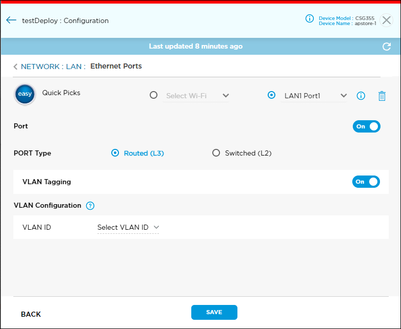
- Select the VLAN ID and then click Continue. To add a new VLAN ID, click the
 icon. See Configure Virtual LANs (Layer 2 and Layer 3 Switching)..

- Click Continue, and then click Save.
Configure an HA Cross-Connect Port
A cross-connect link is the physical connection between the redundant CPE devices in a branch that emulates the missing transport domain and provides redundancy to the attached clients. HA deployments use the cross-connect port. You must allocate one port on each CPE device for the cross-connect port. You can select any of the LAN ports as a cross-connect port. You configure the HA cross-connect port on the primary device, and you cannot delete the cross-connect port from the primary or secondary device.
You must enable the HA cross-connect port in device save mode. After you deploy and activate the device, you cannot change the cross-connect port. Also, the cross-connect port is not displayed in the list of LAN ports.
To configure an HA cross-connect port:
- Click Configure in the left menu bar to open the Configure dashboard.
- Hover over the device in the HA honeycomb, and then click Configure to open the site information window.
- Click Next to open the Configuration > Network screen.
- Click the LAN box to open the Network > LAN screen.
- Click the Ethernet Ports box to open the Network > LAN > Ethernet Ports screen.
- Select a port from the menu to the right of Quick Picks.
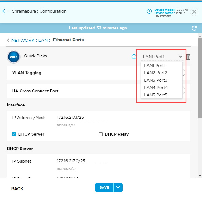
- Click the HA Cross-Connect Port toggle to enable the HA cross-connect port.

- Click Save.
Edit LAN Interfaces on an Active Device
After you configure LAN interfaces and deploy or activate the device, you can make the following changes to a LAN interface:
- Add or remove a WAN, LAN, or LTE interface.
- Switch the gateway on or off.
- Update the transport from internet to MPLS, or vice versa.
- Enable or disable PPPoE.
To make changes to a LAN interface, you must first lock the device using the enable lock mode option in the honeycomb view in the Titan Portal home screen. The lock icon displays only if the device is deployed. A blue lock icon indicates that the device is unlocked, and a red lock icon indicates that the device is locked. After you publish the changes to Titan Portal, you must unlock the device.
To edit LAN interfaces:
- Click Configure in the left menu bar to open the Configure dashboard.

- Click the
 icon in the honeycomb to lock the device.
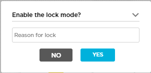
 - Enter the reason for lock in the Enable lock mode popup window, and then click Yes.
- Hover over the device in the honeycomb, and click Configure to open the site information window.
- Click Next to open the Configuration > Network screen.
- Click the LAN box to open the Network > LAN screen.
- Click the Ethernet Ports box to open the Network > LAN > Ethernet Ports screen.
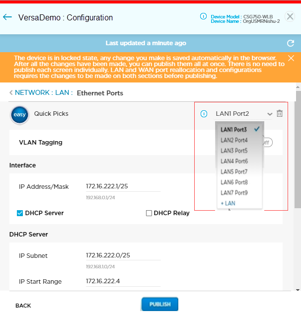
- Click the menu to the right of Easy Quick Picks to view a list of available ports and their LAN numbers.
- Select a LAN/port from the menu.
- Click the
 icon to delete the selected LAN.
 - Click +LAN in the menu, select available ports, and then click Continue to add a new LAN port.

The +LAN is displayed only if number of ports are available to configure in the LAN.
- Click the
- Click Publish, and then click Continue.

- Click the
 icon in the honeycomb to unlock the device, and then click Yes.

Configure WiFi Ports
You can assign a range of IP addresses to each WiFi port. To configure WiFi settings, such as SSID, for WiFi ports see Configure WiFi Networks.
To configure WiFi port settings:
- Hover over the device in the honeycomb, and click Configure to open the site information window.
- Click Next to open the Configuration > Network screen.
- Click the LAN box to open the Network > LAN screen.
- Click the Ethernet and WiFi Ports box to open the Network > LAN > Ethernet Ports screen.

- In the Ethernet Ports screen, select WiFi, click the menu to view a list of available WiFi ports, and then select a WiFi port.

- Enter information for the following fields.
Field Description Port Click Port toggle to enable or disable the WiFi port. VRF Click the VRF list, and then select the VRF. To configure routing, VRF must be associated with a specific LAN or WAN port.
To add a new VRF, click the
 icon. In the Add VRF popup window, enter a VRF name, click the
  icon, and then click Continue. When you add a new VRF, do not use the keyword LAN-VR along with the VRF name.

Address Pool - IP Address/Mask
Enter the IP address and prefix length. The prefix length must be /25. DHCP Server - IP Subnet
Enter a valid IP prefix and length. The length must be /25, for example, 172.16.4.0/25. - IP Start Range
Enter the lowest IP address in the DHCP address pool. - IP End Range
Enter the highest IP address in the DHCP address pool. - DHCP Lease Profile
Select the lease profile for the network level. To add a DHCP lease profile, click the  icon. For more information, see Add a DHCP Lease Profile.
Name Servers By default, primary and secondary DNS name servers are configured automatically. To manually configure these servers, click Manual and enter the IP addresses of the primary and secondary DNS name servers. DHCP Relay - DHCP Relay IP
Enter the IP address of the DHCP relay. Bandwidth (Group of Fields) You can configure uplink bandwidth and downlink bandwidth on the WiFi interface or per VLAN (subinterface). Values entered in Kbps and Gbps are automatically converted to Mbps. - Uplink Bandwidth
Enter the actual uplink bandwidth purchased from the service provider. The uplink bandwidth is the traffic from the branch to the outside network.
Range:- In Kbps—1000 through 40000000 Kbps
- In Mbps—1 through 40000 Mbps
- In Gbps—0.001 through 40 Gbps
- Downlink Bandwidth
Enter the actual downlink bandwidth purchased from the service provider. The downlink bandwidth is the traffic from the outside network to the branch.
Range:
- In Kbps—1000 through 40000000 Kbps
- In Mbps—1 through 40000 Mbps
- In Gbps—0.001 through 40 Gbps
Zone Protection (Group of Fields) - Zone Protection
Select a zone protection profile. To associate a zone protection profile to a network, the profile must be pushed to the device, otherwise the configuration fails with an error.
To add a new zone protection profile, click the
 icon. For more information, see Configure Zone Protection Profiles.
- Logging
Click to configure logging:
- None—Click to perform no logging.
- Default—Click to use default logging.
- Custom—Click to configure logging to a customer log server. Based on the rule match, the device may send a large number of log messages.

- Please Select—If you select Custom, click the down arrow to select a log profile.
To create a new custom flow logs profile, click . For more information, see Add Custom Logs Profile.
- Please Select—If you select Custom, click the down arrow to select a log profile.
- Click Publish.
Configure Port Forwarding
NAT port forwarding, also called port mapping, redirects packets from one address and port number pair to another while the packets are traversing the Titan device. You configure port forwarding rules to allow incoming traffic to reach its destination in the LAN. You should configure WAN ports before configuring port forwarding, because only configured WAN interfaces display in the Port Forwarding screen.
Port forwarding is not enabled by default. To enable it, you configure a rule. When you create a port-forwarding rule, by default, the rule is created in the security firewall rule list, and it has a name in the format port_forwarding_rule_name_frd. You cannot edit or delete a system-generated default rule for port forwarding. However, you can disable or reorder a default rule to change its priority.
To configure a port forwarding rule:
- Hover over the device in the honeycomb and click Configure to open the site information window.
- Click Next to open the Configuration > Network screen.
- Click the LAN box to open the Network > LAN screen.
- Click the Port Forwarding box to open the Network > LAN > Port Forwarding screen.

- In the Port Forwarding screen, click +Rule.

- In the Add Rule screen, enter information for the following fields.
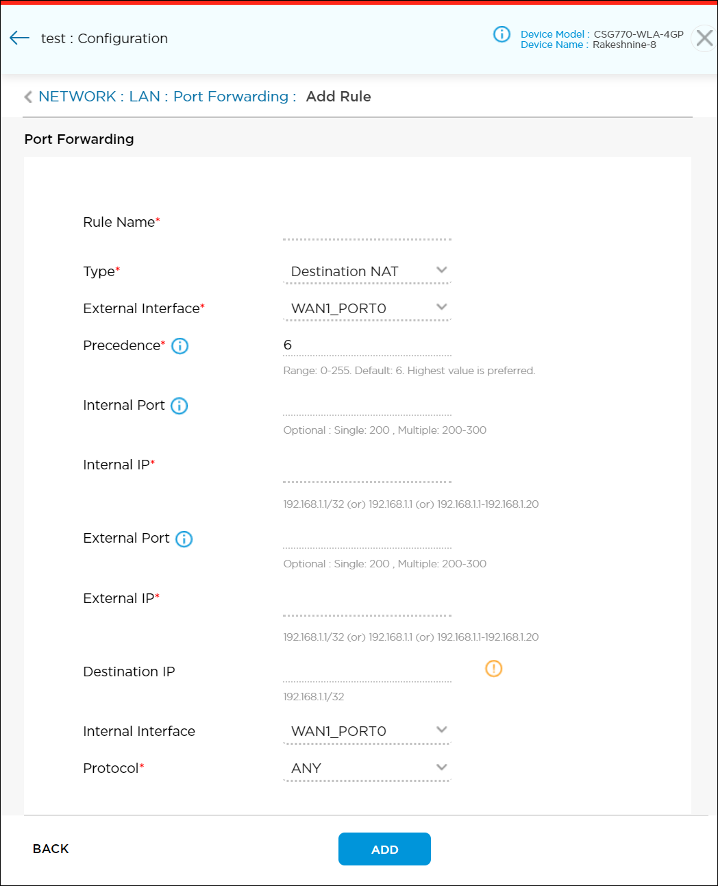
Field Description Rule Name (Required) Enter a name for the rule. Type (Required) Choose the address translation method:
- Destination NAT
- No NAT
- Source NAT
- Static NAT
External Interface (Required) Choose an external WAN interface on which to enable NAT port forwarding. The menu lists only configured WAN interfaces.
When you create a port forwarding rule, the traffic flow for address translation method is as follows:
- If the NAT type is destination NAT, the external interface is the WAN (source) interface and the traffic flow is from the WAN interface to the LAN (destination) servers.
- If the NAT type is static NAT or source NAT, the external interface is the WAN interface and the traffic flow is from the LAN servers to the WAN interface.
- If the NAT type is no NAT, the traffic flow is from the LAN (source) to the WAN interface, and you can select an individual WAN interface or all WAN interfaces.
Precedence (Required) Enter a value for the priority of the rule. You can configure multiple rules and assign each a priority. A rule or rules with a higher priority value take precedence over rules with a lower priority value.
Range: 0 through 255
Default: 6Internal Port Enter the internal port or port range for the LAN interface. You can configure a single port number or a range of port numbers; for example, 200 or 200-300. The type of internal port you configure (single or range) must be the same as the type of external port. For static NAT, you cannot configure an internal port. Internal IP Enter an internal IP address or a range of IP addresses of the LAN servers to which to send NATed traffic. The internal IP addresses must fall within the start and end IP address range of any of the LAN ports. The internal IP type (single or range) must be the same as the external IP type. Internal and external IP ranges must match SNAT rules. External Port Enter the external port or port range for the WAN interface; for example, 2100 or 200-300. The type of external port you configure (single or range) must be the same as the type of internal port. For static NAT, you cannot configure an external port. External IP Enter an external IP address or a range of IP addresses for the WAN interface. The external IP addresses must fall within the start and end IP address range of any of the WAN ports. The external IP type (single or range) must be the same as the internal IP type. Internal and external IP ranges must match SNAT rules. Destination IP Enter a destination IP address. Destination IP is available only for static NAT and source NAT types. Internal Interface Choose an internal interface on which to enable NAT port forwarding. The menu lists only configured WAN interfaces and enterprise LANs.
When you create a port-forwarding rule, the traffic flow for address translation method is as follows:
- If the NAT type is destination NAT, the external interface is the WAN (source) interface and the traffic flow is from the WAN interface to the LAN (destination) servers.
- If the NAT type is static NAT or source NAT, the external interface is the WAN interface and the traffic flow is from the LAN to the WAN interface.
- If the NAT type is no NAT, the traffic flow is from the LAN (source) to the WAN interface, and you can select an individual WAN interface or all WAN interface. When you configure no NAT for any subtenant on a gateway, ensure that you add the security rule in provider organization to allow private IP addresses configured for no NAT.
Note that the internal interface option is displayed only when you configure port-forwarding rules for gateway devices. This option applies only to gateway devices.
Protocol Select the protocol:
- Any
- TCP
- UDP
- Click Add to add the rule to the Titan cloud.

- Click Save to save the new rule to the Titan cloud.
To update a rule:
- Click the rule name to edit the rule, or click X to delete the rule.
- Click Save to update the Titan cloud.
To delete all rules:
- Click Easy Quick Picks. This deletes all port forwarding rules, because the default configuration contains none.
- Click OK in the popup window.
- Click Save to update the Titan cloud.
Reserve an IP Address for a Device
You can permanently assign an IP address to a device by reserving a specific address that is part of the interface's IP address subnet. To reserve an IP address, you can either add a new device by creating a rule or you can click the Add Devices icon to add devices that are already connected. You can also reserve a MAC or an IP address from the WiFi network by associating a device IP reservation rule with WLAN interface ports.
To reserve a device IP address for a device:
- Hover over the device in the honeycomb and click Configure to open the site information window.
- Click Next to open the Configuration > Network screen.
- Click the LAN box to open the Network > LAN screen.
- Click the Device IP Address Reservation box to open the Device IP Address Reservation screen.

- In the Device IP Address Reservation screen, click +Rule.

- In the Add Rule screen, enter information for the following fields.

Field Description Rule Name (Required) Enter a name for the rule. Interface (Required) Select a LAN or WLAN interface name. IP Address (Required) Enter the IP address to reserve. MAC Address (Required) Enter the MAC address of the device for which you are reserving the IP address. - Click the
 Connected Devices icon to view the IP address reservation list for the devices.

- Click Add to add the rule to Titan cloud.

- Click Save to save the new rule to the Titan cloud.
To update a rule:
- Click the rule name to edit the rule.
- Click X to delete the rule.
- Click Save to update the Titan cloud.
To delete all rules:
- Click Easy Quick Picks. This deletes all IP address reservation rules since the default configuration contains none.
- Click OK in the popup window.
- Click Save to update the Titan cloud.
Supported Software Information
Releases 11.2 and later support all content described in this article.
