Configure Appliances, Hubs, and Hub–Controllers
![]() For supported software information, click here.
For supported software information, click here.
The Deploy lifecycle allows you to configure and deploy appliances, hubs, and hub–controllers. You can perform the following tasks:
- Create an appliance, hub, or hub–controller node.
- Set, add, or change a profile on an appliance, hub, or hub–controller.
- Configure the bind variables for an appliance.
- Publish an appliance configuration to Versa Director.
- Activate appliances with ZTP.
- View configuration history.
Create an Appliance, Hub, or Hub–Controller Node
To create a new appliance, hub, or hub–controller node in a site:
- In Tenant view, select the Deploy lifecycle in the left menu bar.
- In Honeycomb, Map, or Table view, double-click the site in which to create the new appliance or hub. The Site Summary screen displays.
- Click + Appliance, + Hub, or + Hub–Controller at the top of the screen.

- If you select + Appliance, enter information for the following fields.

Field Description Name (Required) Enter a name for the appliance. Global Appliance ID Enter a global appliance ID number. If you do not enter an ID number, the system allocates one automatically.
Range: 101 through 16383
Default: None
ZTP Type (Required) Click to select perform ZTP on the appliance:
- Serial Number—Enter the serial number of the appliance.
- URL—Serial number is entered automatically.
Serial Number If you select Serial Number as the ZTP type, enter the serial number of the new appliance. RMA Serial Number Enter the RMA serial number for the device. For more information, see Update the Serial Number for an RMA Device in Concerto. Model Select an appliance model. Staging Controller Select a staging Controller node. VPN Profile Select a VPN profile License Period (Required) (For Releases 11.4.1 and later.) Select the period, in years, for which the license is valid:
- 1 year
- 3 years
- 5 years
Bandwidth (Required) Select the amount of bandwidth that the appliance can use. Site Displays the site name. Email Enter an email address for the site contact Set Template Click Set Template, select the template, and then click Apply. You can also select the template later.
Note that in Releases 12.2.2 this field is called Set Profile.

- If you select + Hub, enter information for the following fields.

Field Description Name (Required) Enter a name for the hub. Global Appliance ID Enter a global appliance ID number. If you do not enter an ID number, the system allocates one automatically.
Range: 101 through 16383
Default: None
ZTP Type (Required) Click to select how to perform ZTP on the hub:
- Serial Number—Enter the serial number of the appliance.
- URL—Serial number is entered automatically.
Serial Number If you select Serial Number as the ZTP type, enter the serial number for the new hub. RMA Serial Number Enter the RMA serial number of the device. For more information, see Update the Serial Number for an RMA Device in Concerto. Model Select a hub model. Staging Controller Select a staging Controller node. VPN Profile Select a VPN profile. License Period (Required) (For Releases 11.4.1 and later.) Select the period, in years, for which the license is valid:
- 1 year
- 3 years
- 5 years
Bandwidth (Required) Select the amount of bandwidth that the hub can use. Site Displays the site name. Email Enter an email address for the site contact. Set Template Click Set Template, select the template, and then click Apply. You can also select the template later.
Note that in Releases 12.2.2 this field is called Set Profile.
- (Releases 11.4.1 and later) If you select + Hub–Controller, enter information for the following fields.
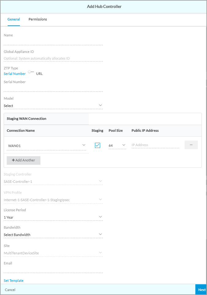
Field Description Name (Required) Enter a name for the hub–controller. Global Appliance ID Enter a global appliance ID number. If you do not enter an ID number, the system allocates one automatically.
Range: 101 through 16383
Default: None
ZTP Type (Required) Click how to perform ZTP on the hub–controller:
- Serial Number—Enter the serial number of the appliance.
- URL—Serial number is entered automatically.
Serial Number If you selected Serial Number as the ZTP type, enter the serial number of the new hub–controller. RMA Serial Number Enter the RMA serial number of the device. For more information, see Update the Serial Number for an RMA Device in Concerto. Model Select a device model. Staging WAN Connection (Group of Fields) - Connection Name
Select WAN connection. If you have enabled staging, this WAN connection is used to perform ZTP on spoke appliances that use this hub–controller. A staging IPsec VPN profile is created for each of the staging-enabled WAN connections. - Staging
Click to enable the staging. - Pool Size
Select the staging pool size:
- 8
- 32
- 64
- 128
- 256
- Public IP Address
If the WAN connection has a public IP address that is different from the IP address of the interface, enter the public IP address of the WAN connection. - + Add Another
Click to add the staging WAN connection and to show the GUI fields to add another staging WAN connection. Click the  Delete icon to remove a connection from the list.
Staging Controller If you have enabled URL ZTP for the hub–controller, select a staging Controller node. VPN Profile Select a VPN profile on the selected staging Controller node. License Period (Required) Select the period, in years, for which the license is valid:
- 1 year
- 3 years
- 5 years
Bandwidth (Required) Select the amount of bandwidth that the hub–controller node can use. Site Displays the site name. Email Enter an email address for the site contact. Set Template Click Set Template, select the template, and then click Apply. You can also select the template later.
Note that in Releases 12.2.2 this field is called Set Profile.

- Click Next. The Permissions tab displays for Add Appliance, Add Hub, and Add Hub-Controller. The screen displays permissions for all of the configured roles. The permission for each role is selected by default, and you can update it. To change permissions for a role, select or deselect the Read, Update, Delete, Set Template, Edit Configuration, Sync From Director, Set Variable, Clear Alarm, and Publish fields for the role. The following screen shows the Permissions tab for the Add Appliance.

- Click Save.
Configure a LAN Interface on an Appliance
You can configure the following LAN interfaces on an appliance:
- Layer 2 Wired—Multiple Layer 2 wired interfaces can have the same Layer 3 integrated routing and bridging (IRB) interface.
- Layer 2 Wireless—Wireless LAN is a network based on radio transmissions rather than wired connections, such as a WiFi network. The devices in a WLAN share a service set identifier (SSID)
- IRB—Associates a Layer 3 interface with a Layer 2 bridge domain so that packets can be routed to and from the bridge domain.
Configure a LAN Interface on an Appliance (Releases 13.1.1 and Later)
To configure a Layer 2 wired, Layer 2 wireless, or an IRB interface on an existing appliance:
- In Tenant view, select the Deploy lifecycle in the left menu bar. The Sites tab is selected by default and displays all configured sites.

- Double-click a site to open it.

- Hover over an appliance hexagon, and then click View Configuration from the action menu. The Edit Main Template screen displays workflow step 1, Deployment Tier and High Availability.
- Select workflow step 2, Network Interfaces.

- Select the LAN tab, and then click Add and select Add New LAN Interface.

- In the Add LAN Interface screen, enter information for the following fields:
- To add a Layer 2 wired interface:
Field Description Category Select LAN or Secondary Device LAN. Sub-Category Select Wired. Interface Type Select the interface type:
- enet
- vni
Interface (Required) Select a VNI or enet interface. VLAN ID Enter a VLAN number.
Default: None
Range: 0 through 4094
Note: For tagged interfaces, use VLAN IDs 1 through 4094. Use VLAN 0 only for an untagged interface.
Link Configuration (Group of Fields) Define the properties for data transmission on the interface. - Speed
Select a speed option for the interface:
- Auto
- 10 Mbps
- 100 Mbps
- 1 Gbps
- 10 Gbps
- 40 Gbps
- 100 Gbps
- Mode
Select the mode for the interface. The options are:
- Auto
- Half duplex
- Full duplex
- MTU
Enter the maximum transmission unit (MTU) size, in bytes, of the largest PDU that the interface can receive or transmit.
Range: 72 through 9000 bytes
Default: None
Is this interface for guests? Click the toggle to enable the interface for guests. When enabled, the interface is designated for guest connectivity only. Guest user traffic is not mixed with enterprise traffic. You can select a routing instance that has been designated for use by guests. Default: Disabled
Routing Instance Name (Required) Select a routing instance for the LAN interface. If you disable the guest user option, you can choose an enterprise routing instance. If you enable the guest user options, choose a guest routing instance. - To add a Layer 2 wireless interface:
Field Description Category Select LAN or Secondary Device LAN. Sub-Category Select Wireless. Wireless LAN (WLAN) (Group of Fields) - Service Set Identifier (SSID)
Enter a value for the SSID. - Broadcast SSID
Click to enable the broadcast identifier. - Protocol
Select the protocol. WiFi Radio (Group of Fields) - Frequency
Select the frequency range.
- 2.4 GHz
- 5 GHz
- WiFi Radio Name (Required)
Select a WiFi radio name. Is this interface for guests? Click the toggle to enable the interface for guests. When enabled, the interface is designated for guest connectivity only. Guest user traffic is not mixed with enterprise traffic. You can select a routing instance that has been designated for use by guests. Default: Disabled.
Routing Instance Name (Required) Select a routing instance for the LAN interface. If you disable the guest user option, you can choose an enterprise routing instance. If you enable the guest user options, choose a guest routing instance. - To add an IRB interface:
Field Description Category Select LAN or WAN. Sub Category Select VLAN interface (IRB or SVI). Interface (Required) Select a VNI or enet interface. VLAN ID VLAN ID—Enter a VLAN number. - Range: 0 through 4094
- Default: None
Note: For tagged interfaces, use VLAN IDs 1 through 4094. Use VLAN 0 only for an untagged interface.
Is this interface for guests? Click the toggle to enable the interface for guests. When enabled, the interface is designated for guest connectivity only. Guest user traffic is not mixed with enterprise traffic. You can select a routing instance that has been designated for use by guests. Default: Disabled.
Routing Instance Name (Required) Select a routing instance for the LAN interface. If you disable the guest user option, you can choose an enterprise routing instance. If you enable the guest user options, choose a guest routing instance.
- To add a Layer 2 wired interface:
- Select step 5, Review and Submit.
- Review the configuration and make any needed changes, and then click Submit.
Configure a LAN Interface on an Appliance (Releases 12.2.2 and Earlier)
To configure a Layer 2 wired, Layer 2 wireless, or an IRB interface on an existing appliance:
- In Tenant view, select the Deploy lifecycle in the left menu bar. The Sites tab is selected by default and displays all configured sites.

- Double-click a site to open it.

- Hover over an appliance hexagon, and then click View Configuration from the action menu. The Edit Appliance Configuration screen displays with the General tab selected by default.

- Select the Profile > Network tab, and then click the LAN box.

- In the LAN screen, click Add Interfaces, then click Create New to add a new interface.
- In the Create Interface screen, select the General tab.

- Enter information for the following fields:
- To add a Layer 2 wired interface:
Field Description Name Enter a name for the Layer 2 interface. Type Select Physical as the interface Type. Enabled Click the toggle to Enabled to enable the interface. Category Select Layer 2. Sub Category Select Wired. Location Select a VNI interface. Interface Mode Select Access or Trunk. VLAN ID If you selected the Access interface mode, enter a VLAN ID.
If you selected the Trunk interface mode, enter one or more VLAN IDs or VLAN ID ranges. Click the
Check icon to add the VLAN ID or VLAN ID range. Click the
 Delete icon to clear the VLAN ID field.
Range: 1 through 4094
Default: None
IRB Membership (Access interfaces only.) Select an IRB of which the Layer 2 interface is a member. Link (Group of Fields) - Speed
Select a link speed for the interface:
- Auto
- 10 Mbps
- 100 Mbps
- 1 Gbps
- Mode
Select the link mode:
- Auto duplex
- Full duplex
- Half duplex
- MTU
Enter a maximum transmission unit (MTU) for the interface.
Range: 72 through 9000
Default: None
- To add a Layer 2 wireless interface:
Field Description Name Enter a name for the Layer 2 interface. Type Select Physical as the interface Type. Enabled Click the toggle to enable the interface. Category Select Layer 2. Sub Category Select Wireless. Virtual Location Select WiFi, and then select a WLAN interface in the field to the right. IRB Membership Select an IRB of which the Layer 2 interface is a member. Radio (Group of Fields) - Frequency
Select a frequency for the interface:
- 2.4 GHz
- 5 GHz
- Profile Name
Select a profile name according to the frequency selected:
- Radio-2.4 GHz
- Radio-5 GHz
Tags Enter one or more tags. A tag is an alphanumeric text descriptor with no white space or special characters. You can add multiple tags for the same object. These tags are used for searching the objects. - To add an IRB interface:
Field Description Name Enter a name for the IRB interface. Type Select Physical as the interface Type. Enabled Click the toggle to enable the interface. Category Select LAN or WAN. Sub Category Select IRB. Location Select an IRB location to which the IRB interface is a member.
- To add a Layer 2 wired interface:
- Click Next, or click the Permissions tab and revise the permissions as desired.
- Click Save.
Set, Add, or Change a Template on an Appliance or Hub
After you create a site and add appliances to it, you add a template to the appliances from the existing templates. You can set templates from any of the Deploy lifecycle views—honeycomb, map, or table. You can change an appliance's template using the same procedure.
Set, Add, or Change a Template on an Appliance or Hub (Releases 13.1.1 and Later)
- In Tenant view, select the Deploy lifecycle in the left menu bar.
- Select a site that has one or more appliances.

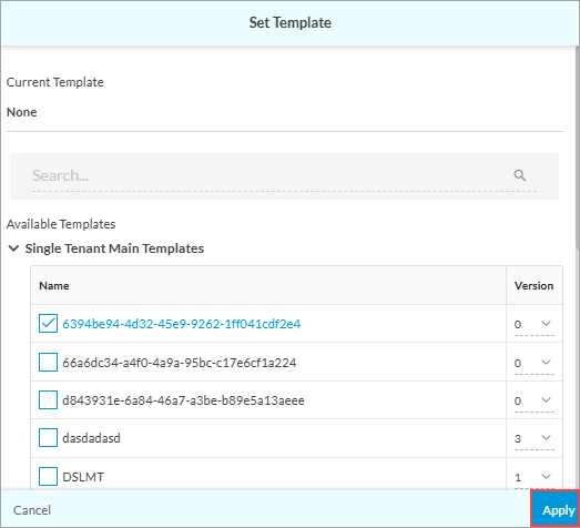
- To assign a template to the appliances, click Set Template. The Set Template screen displays.

- Select one or more appliances, and then click Next. The Choose Profile tab displays.

- In the Search box, search for a template, or select a template from the list of available templates. Note that you can apply different versions of the same templates to different appliances.
- Click Apply.
- To publish the new or changed template for the site, select the Publish command in the Honeycomb, Map, or Table views.

When you modify a reusable object, such as a main template, it becomes a custom version. Creating a custom template does not create a new version of the main template, and the change is not added to the repository of reusable objects.
For example, in the screenshot below, the profiles HQ-Device-Profile version 4 and WestCoast-Security version 2 have been modified, so the version is appended, as indicated by the word Custom.

To display summary information about a site, double-click the site. The Site Summary displays the templates that are assigned to each site.

Set, Add, or Change a Profile on an Appliance or Hub (Releases 12.2.2 and Earlier)
- In Tenant view, select the Deploy lifecycle in the left menu bar.
- Select a site that has one or more appliances.

- To assign a profile to the appliances, click Set Profile. The Set Profile screen displays.

- Select one or more appliances, and then click Next. The Choose Profile tab displays.

- In the Search box, search for a profile, or select a profile from the list of available profiles. Note that you can apply different versions of the same profile to different appliances.
- Click Apply.
- To publish the new or changed profile for the site, select the Publish command in the Honeycomb, Map, or Table views.

When you modify a reusable object, such as a master profile, it becomes a custom version. Creating a custom profile does not create a new version of the master profile, and the change is not added to the repository of reusable objects.
For example, in the screenshot below, the profiles HQ-Device-Profile version 4 and WestCoast-Security version 2 have been modified, so the version is appended, as indicated by the word Custom.
To display summary information about a site, double-click the site. The Site Summary displays the profiles that are assigned to each site.

Download Template Assignments in CSV Format
For Releases 11.3.2 and later.
You can download a report to a file in CSV format that shows which devices are assigned a specific template, and also download a report that shows all the devices at a site and which templates are assigned to them.
Note: For Releases 12.2.2 and earlier, the Template Assignment section of the Site Summary pane was called Profile Assignment.
To download template assignments reports to a file in CSV format:
- Go to the Deploy lifecycle. All configured sites display, along with a summary of all the sites in the right-hand pane.

- In the Template Assignment section of the Site Summary, click the
 Expand icon. The Profile Usage screen displays with the first profile in the list highlighted in the main pane and in the Summary pane (profile kpt1.v1-Custom in the example below). You can click the name of a different profile in the main pane to see the details of the appliances assigned to that profile in the Summary pane.

- To download the summary information for the highlighted profile, click the
 Download icon in the Summary pane.
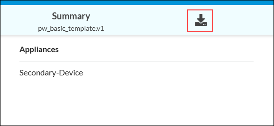
The summary information downloads to a file in CSV format, similar to the following:

- To download a report that shows all the devices at a site and which profiles are assigned to them, click the Download icon to the left of the Publish button.

The information downloads to a file in CSV format.
Activate Appliances with ZTP
After an appliance's configuration is published, the Director and Controller nodes have all the configuration information needed to accept the appliance into the enterprise network. The appliance, either a physical or virtual appliance, is bootstrapped using the ZTP process based either on the serial number or the URL, depending on the configuration. When the appliance completes the ZTP process, the hexagon edge color in Honeycomb view changes from gray to blue, indicating that the ZTP process has completed and the appliance is now connected to the Director node.
View the Configuration Publish History
You can view and compare the publish history of configuration changes made locally in Concerto. You can compare any two published configurations, and you can also compare an unpublished version with the last published version.
Note: You cannot compare configuration changes made in Versa Director.
View the Configuration Publish History (Releases 13.1.1 and Later)
To view the configuration history and compare versions:
- In the left menu bar, select Deploy to display all sites in Honeycomb view.
- Double-click a site hexagon, hover over an appliance hexagon, and click View Publish History.

- The View Publish History pane displays the configuration version history for the appliance.
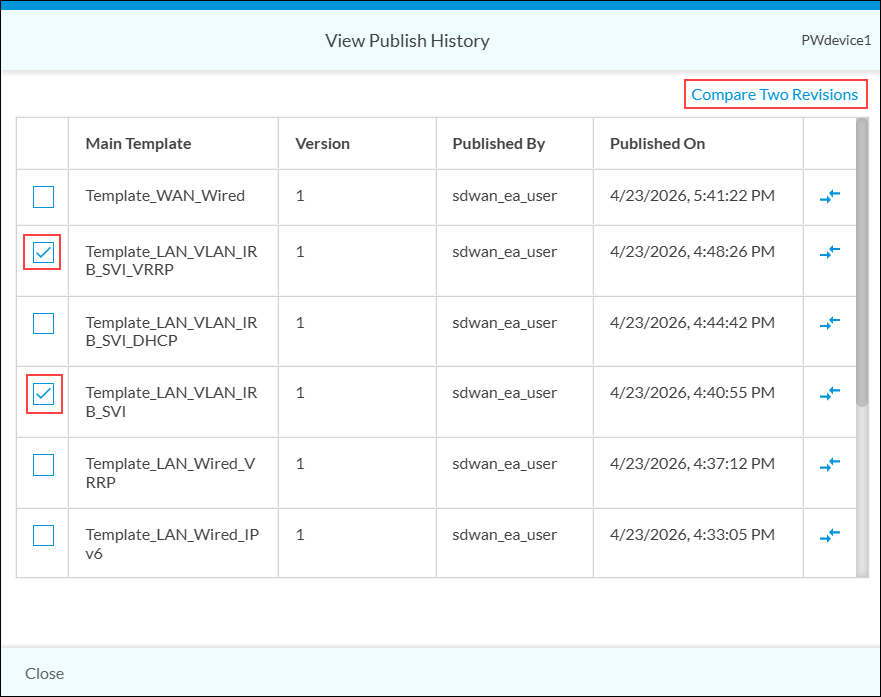
- To compare versions of published configurations, click the checkbox next to the desired versions, and then click Compare Two Revisions. The Configuration Diff screen displays.

- To download a text file of a configuration, click the
 Download icon.
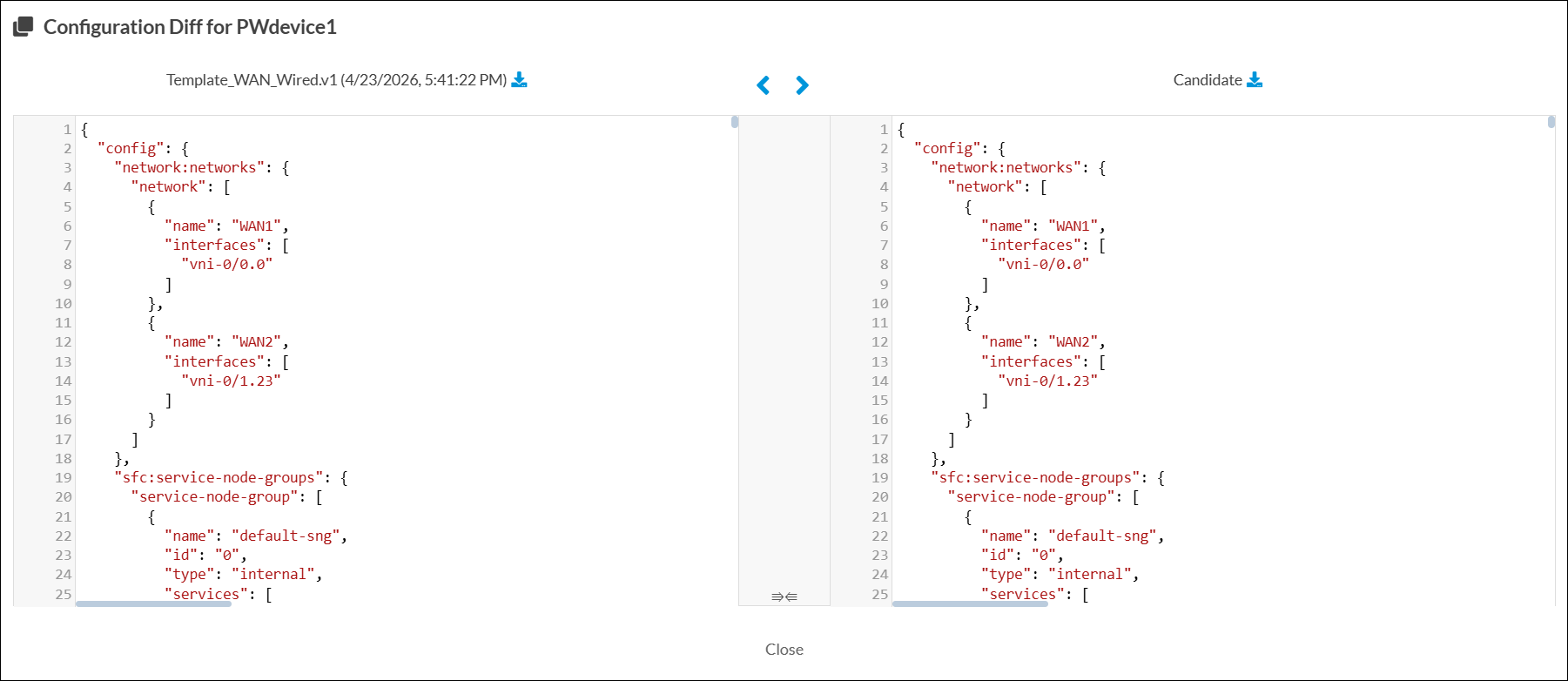
 - To view the differences between a published configuration and a current unpublished configuration, click the
Arrows icon to the right of one of the versions.
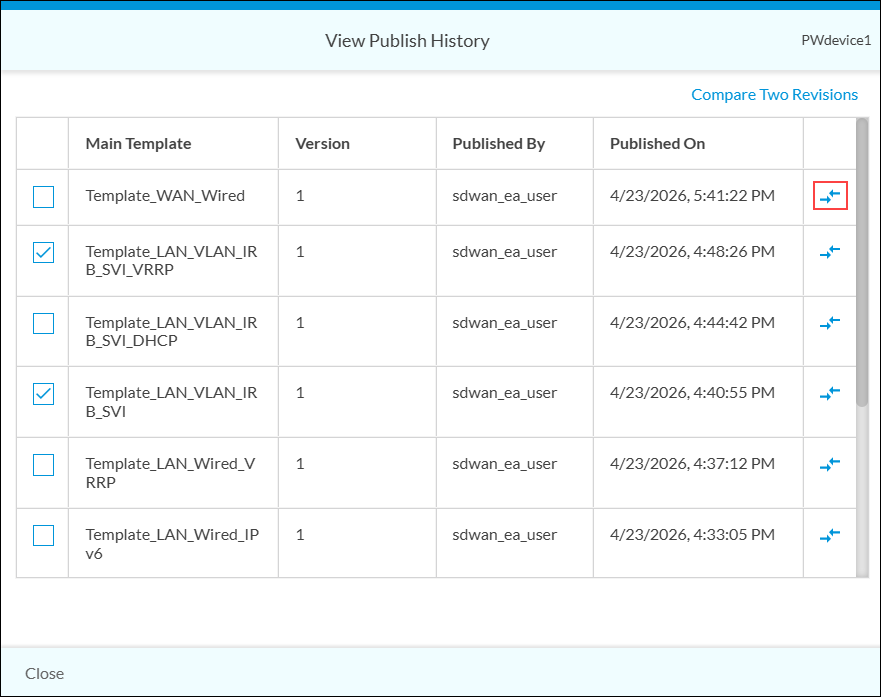
The Configuration Diff screen displays. The unpublished configuration is on the right-side and is labeled Candidate.
- Click Close.
View the Configuration History (Releases 12.2.2 and Earlier)
To view the configuration history and compare versions:
- In the left menu bar, select Deploy to display all sites in Honeycomb view.
- Double-click a site hexagon, hover over an appliance hexagon, and click View History.

- The View History pane displays the configuration version history for the appliance.

- To compare versions of published configurations, click the checkbox next to the desired versions, and then click Compare. The Configuration Diff screen displays.

- To download a text file of a configuration, click the Download icon.
- To view the differences between a published configuration and a current unpublished configuration, click the
Arrows icon to the right of one of the versions.

The Configuration Diff screen displays. The unpublished configuration is on the right and is labeled Current.

- Click Close.
Supported Software Information
Releases 10.1.1 and later support all content described in this article, except:
- Release 10.2.1 adds support for configuring Layer 2 wired and wireless interfaces and IRB interfaces on an appliance.
- Release 11.3.2 adds support for downloading a report to a file in CSV format that shows which devices are assigned a specific profile, and for downloading a report that shows all the devices at a site and which profiles are assigned to them.
- Release 11.4.1 adds support for configuring hub–controller nodes on appliances and choosing a license period option for appliances and hubs.
- Release 13.1.1 introduces a new configuration workflow for adding LAN interfaces.