Configure Layer 3 SD-WAN Traffic Steering Based on Available Bandwidth
![]() For supported software information, click here.
For supported software information, click here.
When a Layer 3 SD-WAN deployment has multiple WAN links and multiple paths to reach a destination, SD-WAN traffic steering chooses the best path to send traffic to its destination. SD-WAN traffic steering chooses the best path using statically configured methods, either the CoS shaping rate or the uplink and downlink bandwidths configured on the interface. For Releases 21.2.1 and later, you can also configure SD-WAN traffic steering to choose the best path dynamically, by monitoring WAN path capacity and choosing the path that currently has the most available bandwidth. To use either the static or dynamic method to choose the best path, you configure the connection selection method in an SD-WAN traffic steering forwarding profile.
By default, when an SD-WAN site has multiple WAN paths to a destination, traffic is load-balanced per flow using weighted round-robin (WRR), and all packets for a given flow are sent over one path. To choose the WAN connection to use, you can select one of four methods. The default is WRR, which balances flows onto paths proportional to their available bandwidth, and you can also use the path that has the most available bandwidth. Both of these methods choose the best path using either the configured CoS shaping rate or the configured interface uplink and downlink bandwidths. For Releases 21.2.1 and later, you can also use path WRR and path high-available bandwidth, which both dynamically monitor and periodically compute the available path bandwidth across all paths towards the remote site. These two methods then load-balance the traffic flows across the available paths using either WRR or the path that has the most available bandwidth, respectively.
When you use path WRR or path high-available bandwidth as the connection selection method, if a path bandwidth monitor is not available or not enabled for a remote branch, the local VOS device uses local acknowledgment-based load balancing, that is, either WRR or high available bandwidth, respectively. If automatic path bandwidth is enabled on the remote branch, but the monitored bandwidth value is not available for one of the paths, the local VOS device assumes that that path has highest available bandwidth capacity.
Note that you should use the path WRR and path high-available bandwidth connection selection methods only in hub-and-spoke topologies. Do not use them in full-mesh topologies.
The path WRR and path high-available bandwidth connection selection methods maintain a historical maximum of the monitored available bandwidth for each path over a period of time, which helps the path selection software identify long-term bandwidth trends at specific times of day.
To dynamically monitor the available bandwidth on each WAN circuit, you must do the following:
- Configure a speed-test server. For more information, see Configure a Versa Speed-Test Server in Troubleshoot Link Bandwidth Issues.
- Enable bandwidth monitoring on the VOS device.
- Configure bandwidth monitoring.
- Configure an SD-WAN traffic steering forwarding profile, and select the path WRR or path high-available bandwidth connection selection method. For more information, see Configure Layer 3 SD-WAN Traffic-Steering Forwarding Profiles.
This article describes how to enable and then configure bandwidth monitoring.
Enable Bandwidth Monitoring
To enable the use of monitored bandwidth for traffic steering:
- In Director view:
- Select the Configuration tab in the top menu bar.
- Select Templates > Device Templates in the horizontal menu bar.
- Select an organization in the left menu bar.
- Select a post-staging template in the main pane. The view changes to Appliance view.
- Select the Configuration tab in the top menu bar.
- Select Others > System > Speed Test in the left menu bar. The Speed Test screen displays.
- Click the Settings tab in the Speed Test screen.

- Click the
 Edit icon in the Client Options pane.
 - In the Monitored Bandwidth Usage field, select Enabled.
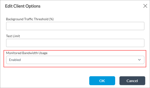
- Click OK.
Configure Bandwidth Monitoring
To configure monitored bandwidth for steering SD-WAN traffic:
- In Director view:
- Select the Configuration tab in the top menu bar.
- Select Templates > Device Templates in the horizontal menu bar.
- Select an organization in the left menu bar.
- Select a post-staging template in the main pane. The view changes to Appliance view.
- Select the Configuration tab in the top menu bar.
- Select Others > System > Speed Test in the left menu bar. The Speed Test screen displays.
- Click the Auto Bandwidth Measurement tab in the Speed Test screen.
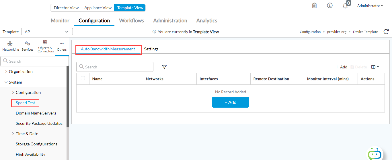
- Click the
 Add icon. In the Add Bandwidth Measurement popup window, enter information for the following fields.

Field Description Name (Required) Enter a name for the speed-test client. Remote Destination (Required) Enter the IP address of the device to which the speed test will be run. Monitor Interval (Required) Enter the interval between speed tests, in minutes.
Default: 30 minutes
Range: 5 to 300 minutes
Networks or Interfaces (Group of Fields) Select either a network or interfaces to use for the speed test. You cannot select both. - Networks
Select a network to use for the speed test. - Interfaces
Click the  Add icon, and select up to 8 interfaces from which to run the speed test.
 - Click OK.
Supported Software Information
Releases 21.2.1 and later support all content described in this article.
Additional Information
Configure CoS
Configure Interfaces
Configure SD-WAN Traffic Steering
Troubleshoot Link Bandwidth Issues