CSG1000 Series Hardware Guide
At a Glance
The Versa Cloud Services Gateway (CSG) 1000 series appliances deliver carrier-grade reliability, high performance, and high compute capacity for enterprise-grade routing, SD-WAN, next-generation security, and uCPE scenarios. They are designed for deployment in large enterprise branches, campus sites, or data centers that require advanced secure SD-WAN along with comprehensive advanced application and cloud-intelligent SD-WAN services on premises.
The CSG1000 series appliances come with LAN and WAN ports, including Ethernet and non-Ethernet (ADSL2+/VDSL2 and T1/E1) interfaces and wireless (3G, 4G LTE, LTE Advanced, 5G, and WiFi access point) WAN and LAN access technologies.
These appliances provide the following features:
- Support for different CPUs and memory sizes
- Interface ports
- One RJ45 1-Gigabit Ethernet port
- One RJ45 serial console port
- Two RJ45 10-Gigabit Ethernet ports for WAN Interfaces
- Eight RJ45 1-Gigabit Ethernet PoE (30 W) ports for LAN Interfaces
- Two SFP+ 10-Gigabit Ethernet ports for WAN Interfaces
- Four SFP+ 10-Gigabit Ethernet ports for LAN Interfaces
- Two USB 2.0 management port for plugging in external LTE or WiFi modems
- Two LTE wireless interface
- Two WiFi wireless interface
- Field replaceable 1+1 redundant, hot-swappable power supply units (PSUs)
- Field replaceable 3+1 fans for cooling
- Rack-mountable in a 19-inch rack.
- Two of the 10-Gigabit Ethernet interfaces are multirate copper interfaces capable of operating as 1- or 10-Gigabit Ethernet interfaces.
- The remaining 10-Gigabit Ethernet interfaces have SFP+ ports that support 10-Gigabit Ethernet or 1-Gigabit Ethernet fiber or copper modules.
CSG1000 Series Appliance Models
The CSG1000 series appliances are available in the following models:
- CSG1300, with 128 GB of storage
- CSG1500, with 256 GB of storage
Chassis Views
The CSG1300 series and CSG1500 series appliances are physically identical.
The front panel is the side of the appliance with the SIM slots, LEDs for status and power, soft reset button, and various connectors and ports. It also has integrated rack-mount ears for installation in standard 19-inch racks. This is the side that is visible when you install the appliance in an office environment.
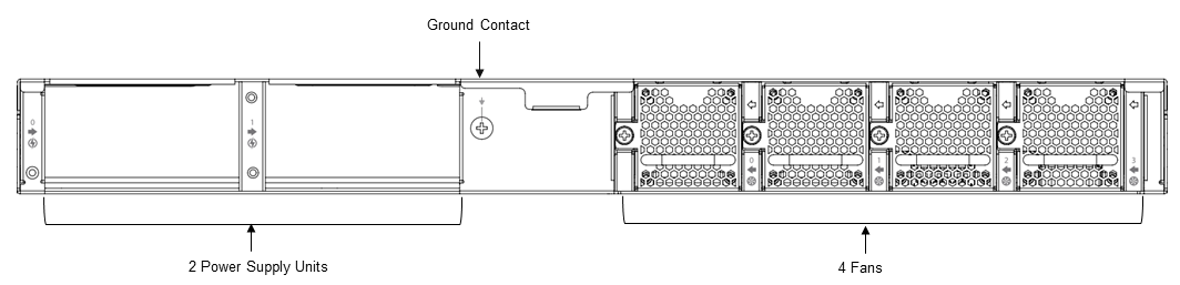
The rear panel has the power supply units, ground contact, and cooling fans. This is the side that is visible when you mount the appliance in a 19-inch rack.
Figure 1 and Figure 2 show the front and rear panels of a CSG1500 series appliance.
Figure 1: Front Panel of a CSG1500 Series Appliance

Figure 2: Rear Panel of a CSG1500 Series Appliance

Front and Rear Panel Components
This article describes the front and rear panel components of a Cloud Services Gateway (CSG) 1000 series appliance. For the exact location of these components on the appliance, see At a Glance.
Front Panel
The front panel of a CSG1000 series appliance has a power button, a reset button, and six status LEDs located in two rows, as shown in Figure 1. (Note that the CSG1300 series and CSG1500 series appliances are physically identical.)
Figure 1: Front Panel of a CSG1500 Series Appliance

LEDs
Table 1 lists the LEDs, their colors and states, and the status they indicate.
Table 1: Front Panel LEDs in a CSG1000 Series Appliance
| LED | Color | Status |
|---|---|---|
| Power | Green |
|
| Status | Green, Red |
|
| Cloud | Green, Red | Currently not supported. |
| Wireless | White |
|
| LTE | White |
|
Power Button
The Power button on the front panel of a CSG1000 series appliance turns the power on and off.
To turn the power on, press and immediately release the Power button when the appliance is off.
To turn the power off, press the Power button when the appliance is on, as follows:
- If you press and immediately release the button, the appliance does a graceful software shutdown that is equivalent to issuing the shutdown now command from the operating system shell.
- If you press and hold the button for 10 seconds or more, the power for the appliance turns off and the appliance shuts down.
Reset Button
The Reset button on the front panel of a CSG1000 series appliance resets the appliance. The reset functionality depends on the number of times you press the button within a span of 30 seconds, as described in Table 3. In between each press on the reset button, you must pause for a second to register the key presses.
The Reset button is recessed so that it is not accidentally pressed while the appliance is operational.
To press the Reset button, use a sharp, narrow tool.
Table 3: Reset Button Press Behavior
| Number of Presses |
Behavior |
|---|---|
| 2 | Reset the appliance to the factory-default snapshot. |
| 4 | Reset the appliance to the branch prestaging configuration. |
| 6 | Reset the appliance to the branch staging configuration. |
| 8 | Reset the appliance to branch post-staging configuration. |
You can reset the appliance to the factory-default configuration by issuing the request system reset CLI command.
SIM Card Slots
The front panel of a CSG1000 series appliance has two nano-SIM card slots. If you subscribe to a single wireless service, install the LTE device in the SIM 1 slot. If you subscribe to dual wireless services, use both the SIM 1 and SIM 2 slots to activate the LTE devices.
Note: It is strongly recommended that you use only preactivated SIMs in the SIM card slots.
Reset the Appliance to the Factory-Default Configuration from the CLI
You can reset the appliance to the factory-default configuration from the CLI. You can connect to the appliance through the serial console port or by using SSH.
The factory default reset procedure may take up to 20 minutes to complete. Do not power off the appliance during this time.
To reset an appliance to the factory default configuration:
- To connect to the appliance through the serial console port, see Configure a Management Console to Connect to a CSG1000 Series Appliance.
- Log in to the appliance CLI. Please consult Versa technical support for default credentials.
Note: To connect to the appliance using SSH, connect your PC to the management port of the appliance. For the port mapping on the CSG1000 series appliance, see Interface Numbering. The management port has the default static IP address 10.10.10.10/24. Configure the PC IP address to any IP from this segment, for example, 10.10.10.1/24. Open an SSH session to the appliance using its IP address, 10.10.10.10.
- Issue the following commands to reset the configuration to factory default. If the current software version on the appliance is the same as that of the factory reset snapshot, the procedure takes about 10 minutes to complete. If the software versions are different, the procedure takes about 20 minutes to complete. Do not power off the appliance during the process.
% cli
% request system reset
- Verify that all Versa services are running by issuing the vsh status command from the Linux bash CLI. The following is a sample output of this command. If all the services are shown as stopped, issue the vsh start command from the Linux bash CLI to start them manually.
# vsh status
versa-service    is Running, [*] process 6784
versa-infmgr     is Running, [-] process 5623
versa-rfd        is Running, [-] process 5838
versa-vmod       is Running, [-] process 5839
versa-ip2user    is Running, [-] process 5844
versa-imgr       is Running, [-] process 5848
versa-acctmgrd   is Running, [-] process 5845
versa-fltrmgr    is Running, [-] process 5648
versa-vstated    is Running, [-] process 5625
versa-addrmgrd   is Running, [-] process 5857
versa-rt-cli-xfm is Running, [-] process 5798
versa-rtd        is Running, [-] process 5827
versa-dhcpd      is Running, [-] process 5620
versa-eventd     is Running, [-] process 5843
versa-vrrpd      is Running, [-] process 5643
versa-dnsd       is Running, [-] process 5646
versa-ppmd       is Running, [-] process 5793
versa-snmp-xform is Running, [-] process 5800
versa-certd      is Running, [-] process 5849
versa-ntpd       is Running, [*] process 5612
versa-dhclient6  is Running, [-] process 5807
versa-redis      is Running,[-] process 6927
versa-av-redis   is Running, [-] process 5003
versa-spackmgr   is Running, [-] process 5832
versa-monit      is Running, [*] process 6078
versa-confd      is Running, [*] process 4798
versa-fail2ban   is Running, [*] process 6093
versa-auditd     is Running, [*] process 6116
versa-nodejs     is Running, [-] process 5775
- Power off the appliance.
Rear Panel
The rear panel of a CSG1000 series appliance has the following components, as shown in Figure 2:
- Two power supply units, internal 920 W, that provide 1+1 redundancy, hot-swappable, with back-to-front airflow and AC to DC
- Four front-to-back cooling fans that provide 3+1 redundancy
- One ground contact
Figure 2: Rear Panel of a CSG1000 Series Appliance
Additional Information
Network Interface Cards
The Cloud Services Gateway (CSG) 1000 series appliances offer field-based configurability using the network interface card (NIC) slot. This article describes the CSG1000 appliance NICs.
NIC Types
Table 1 describes the NICs and the Versa Operating SystemTM (VOSTM) software releases in which the NIC is supported.
Table 1: CSG1000 Series Appliance NIC Support
| NIC Type and Model | NIC Options | Description | VOS Support |
|---|---|---|---|
| Gigabit Ethernet | |||
|
4-port RJ45 copper Gigabit Ethernet PoE/PoE+, 60 W |
|
Releases 21.1.1 and later |
|
4-port RJ45 copper Gigabit Ethernet PoE/PoE+, 120 W |
|
Releases 21.1.1 and later |
| ADSL+/VDSL | |||
|
1 RJ45 port ADSL+/VDSL, Annex A |
|
Releases 21.1.1 and later |
|
1 RJ45 port ADSL+/VDSL, Annex B |
|
Releases 21.1.1 and later |
| T1/E1 | |||
|
4 RJ-45 ports T1/E1 |
|
Releases 21.1.1 and later |
To supplement the eight built-in PoE+ ports, you can add a 4-port copper Gigabit Ethernet PoE+ NIC, to provide twelve PoE+ ports. CSG1000 appliances and the optional 4-port PoE+ NIC support the 802.3af and 802.3at standards. Note that an external power supply unit is required for the optional 4-port PoE+ NIC. Figure 1 shows the four RJ45 connectors for the four Ethernet ports (1-GB copper Gigabit Ethernet port and 1-GB copper Gigabit Ethernet with PoE port.)
Figure 1: CSG1500 RJ-45 Connectors for 1-GB Copper Gigabit Ethernet Ports

NIC Specifications
Table 2 lists the NIC specifications for a CSG1000 series chassis.
Table 2: CSG1000 Series NIC Specifications
| Items | Specifications |
|---|---|
|
Item Specification |
|
| Typical power consumption | 10 Watts |
| System power input | 3.3 VDC @ 3A |
| PoE power adapter input | 54 VDC @ 2.78A, 100-240 VAC @ 2A, 50-60 Hz |
|
Physical Specifications |
|
| Height | 1.54" (39 mm) |
| Width | 3.25" (82.5 mm) |
| Depth | 5.52" (140 mm) |
| Weight | |
|
0.33 lb (150 gm) |
|
0.44 lb (200 gm) |
|
0.33 lb (150 gm) |
|
0.44 lb (200 gm) |
|
0.33 lb (150 gm) |
|
Package Specifications |
|
| Package height | 3.25" (82.55 mm) |
| Package width | 6" (152.4 mm) |
| Package depth | 9" (228.6 mm) |
| Package weight | 0.77 lb (350 gm) |
|
Operating Conditions |
|
| Temperature | 0 to 40°C (32 to 104°F) |
| Humidity | 10 to 85% relative humidity |
| Altitude | Maximum 3000 m (10000 ft) |
| Noise level | 0 dBm |
|
Storage Conditions |
|
| Temperature |
–20 to 70°C (–4 to 158°F) at sea level |
| Humidity | 10 to 85% relative humidity |
DSL NIC Modules
Versa CSG series appliances have digital subscriber line (DSL) capabilities, with interfaces that can operate in asymmetric digital subscriber line (ADSL2+) mode and very high speed digital subscriber line (VDSL2) mode networks. ADSL2+/VDSL2 NIC modules support a single WAN interface, allowing you to connect to ADSL2 and VDSL2 networks, providing high-speed digital data transmission between customer premises equipment (CPE) and DSL access multiplexers (DSLAMs).
You can use ADSL2+/VDSL2 NIC modules to upgrade existing xDSL infrastructure. You can install or remove them on a CSG300 series appliance while the appliance is powered off. These modules have built-in impulse over-voltage protection.
ADSL2+/VDSL2 NIC modules are built on a high performance chipset that conforms to VDSL2 or ADSL2+ standards, driving data rates up to 200+ Mbps downstream and upstream directions on twisted pair copper connections using a carrier band up to 30 MHz. The ADSL2+/VDSL2 NIC module is available in two SKUs with the following standards supported:
- Annex A for POTS-based DSL line connections
- VDSL2: ITU-T G.993.2 Profiles 8, 12, 17, 30 MHz
- VDSL2 G.993.2 Profile 8a, 8b, 8c, 8d, 12a, 12b, 17a. 30a
- ADSL: ITU-T G.992.1/3/5 Annexes A, L and M
- ITU-T G.993.5 Vectoring
- ITU-T G.998.4 PHY Layer Re-Transmission profiles up to 30 MHz
- Annex B for ISDN-based DSL line connections
- VDSL2: ITU-T G.993.2 Profiles 8, 12, 17, 30 MHz
- VDSL2 G.993.2 Profile 8a, 8b, 8c, 8d, 12a, 12b, 17a. 30a
- ADSL: ITU-T G.992.1/3/5 Annexes B and J, T1.413
- ITU-T G.993.5 Vectoring
- ITU-T G.998.4 PHY Layer Re-Transmission profiles up to 30 MHz
You can deploy Versa Operating SystemTM (VOSTM) SD-WAN, security, routing, and network performance management features on ADSL2+ and VDSL2 interfaces. VDSL2 interfaces support triple-play services, such as voice, video, data, and high-definition television (HDTV).
ADSL2+ and VDSL2 interfaces support the following encapsulation types:
- Point-to-Point Protocol over Ethernet (PPPoE)
- Point-to-Point Protocol over Ethernet over ATM (PPPoEoA)
- VLAN
You can configure ATM, LLC, or VC-MUX-based transparent bridging for the NIC with the virtual path identifier (VPI)/virtual channel identifier (VCI) configuration option. VOS network packet processing includes a full set of Layer 2, Layer 3, and Layer 4 to Layer 7 functions, including VLAN and other methods to separate traffic.
Versa Networks recommends using surge protection devices for WAN lines, such as on DSL lines, to protect appliances from electrical surge and spikes that can come from the copper wire. For more information, see Surge Protection for WAN Lines.
Interface Numbering
Figure 1 shows the mapping of the Ethernet ports to virtual network interface (VNI) numbering for the CSG1000 series appliance. Note that the CSG1300 and CSG1500 chassis are identical.
Figure 1: CSG1500 Port-to-VNI Mapping

Figure 2 shows port-to-VNI mapping for the CSG1300 and CSG1500 appliances. Note that the CSG1300 and CSG1500 chassis are identical.
Figure 2: CSG1300 and CSG1500 Port-to-VNI Mapping

Installation Guidelines
This article provides general safety standards and warnings relating to installing or connecting a CSG1000 series appliance.
General Safety Guidelines
Caution: Before installing or removing a CSG1000 series appliance, ensure that the appliance chassis is electrically connected to ground. When you are installing or removing an appliance, ensure that you wear an ESD grounding wrist strap. To put the ESD grounding strap on properly, attach it to an ESD point and then place the other end of the strap around your bare wrist, making good skin contact. Failure to use an ESD grounding strap could damage the appliance.
- Install the CSG1000 series appliance in compliance with the following local, national, and international electrical codes:
- United States—National Fire Protection Association (NFPA 70), United States National Electrical Code.
- Other countries—International Electromechanical Commission (IEC) 60364, Part 1 through Part 7.
- Evaluated to the TN power system.
- Canada—Canadian Electrical Code, Part 1, CSA C22.1.
- Locate the emergency power-off switch in the installation area. In case of an electrical accident, turn off the power quickly.
- Disconnect power to the appliance before installing or removing it.
- Disconnect power from the circuit that is being used for the appliance.
- If hazardous conditions exist, do not work alone.
- If you are working under conditions that might be hazardous to the eyes, wear safety glasses or goggles.
Caution: There is a risk of explosion if the battery is replaced by an incorrect type.
Federal Communication Commission Interference Statement
This device complies with Part 15 of the FCC Rules. Operation is subject to the following two conditions: (1) This device may not cause harmful interference, and (2) this device must accept any interference received, including interference that may cause undesired operation.
This equipment has been tested and found to comply with the limits for a Class A digital device, pursuant to part 15 of the FCC Rules. These limits are designed to provide reasonable protection against harmful interference when the equipment is operated in a commercial environment. This equipment generates, uses, and can radiate radio frequency energy and, if not installed and used in accordance with the instruction manual, may cause harmful interference to radio communications. Operation of this equipment in a residential area is likely to cause harmful interference in which case the user will be required to correct the interference at his own expense.
If this equipment does cause harmful interference to radio or television reception, which can be determined by turning the equipment off and on, the user is encouraged to try to correct the interference by one of the following measures:
- Reorient or relocate the receiving antenna.
- Increase the separation between the equipment and receiver.
- Connect the equipment into an outlet on a circuit different from that to which the receiver is connected.
- Consult the dealer or an experienced radio/TV technician for help.
FCC Caution: Any changes or modifications not expressly approved by the party responsible for compliance could void the user's authority to operate this equipment.
This transmitter must not be collocated or operating in conjunction with any other antenna or transmitter.
Radiation Exposure Statement
This equipment complies with CE and FCC radiation exposure limits set forth for an uncontrolled environment. This equipment should be installed and operated with minimum distance 20 cm between the radiator and your body.
Warning: Operation of this equipment in a residential environment could cause radio interference.
Warning: Operation of this equipment is for indoor use only.
NBTC Thailand (SDoC) Statement
This telecommunication equipment conforms to the standard or technical requirements of NBTC.
เครื่องโทรคมนาคมและอุปกรณ์นี้ มีความสอดคลอ้ งตามมาตรฐานหรือขอ้ กำหนดทางเทคนิคของ กสทช.
QR Code

Install a CSG1000 Series Appliance
This article provides instructions about how to unpack a Cloud Services Gateway (CSG) 1000 series appliance and how to mount a CSG1000 series appliance in a 19-inch rack.
Unpack a CSG1000 Series Appliance
The CSG1000 series appliance is packed in a plastic box, and it is shipped in a cardboard carton, secured with foam packing material. The carton also contains an accessory box. It is recommended that you unpack the appliance only when you are ready to install it.
To unpack a CSG1000 series appliance:
- Open the top flaps of the cardboard carton.
- Remove from the box the foam packing material holding the appliance and the accessories in place. See Figure 1.
- Remove the accessory box and the appliance from the foam packing material.
- Remove the accessories from the accessories box.
- Verify the components against the packing list that is included in the box.
Figure 1: Unpack a CSG1000 Series Appliance

Note: It is recommended that you save the shipping carton and packing material when unpacking the appliance, in case you need to later move the appliance or return it. See How To Return Hardware.
Packing List for the CSG1000 Series Appliance
The cardboard carton in which a CSG1000 series appliance is shipped contains a packing list. Check the packing list against the parts that you receive in the shipping carton.
Table 1 lists the parts shipped with a CSG1300 or CSG1500 appliance.
Table 1: Parts Shipped with a CSG1300 or CSG1500 Appliance
| Components | Quantity |
|---|---|
| CSG1300 or CSG1500 appliance chassis | 1 |
| Power cable (US only) | 1 |
| LTE antenna (included only with LTE module) | 2 |
| WiFi antenna (included only with WiFi module) | 2 |
| Grounding wire (#18 AWG) | 1 |
| Rear-post brackets | 2 |
| Rear-post bracket ears | 2 |
| Screws for ear locking | 2 |
| Screws for rack mounting |
4 (size M6) |
| Screws |
20 (size M4) |
Warning: This equipment is not suitable for use in locations where children are present.
Mount a CSG1300 or CSG1500 Appliance in a Rack
You can mount a CSG1300 or CSG1500 appliance in a four-post 19-inch rack. Two people are required to mount the appliance.
To mount the appliance, ensure that you have the following tools:
- Number 2 Phillips (+) screwdriver
- Tape measure
To mount a CSG1300 or CSG1500 appliance in a four-post 19-inch rack:
- Place the appliance chassis on a flat, stable surface.
- Check the internal dimensions of the rack with a tape measure. The appliance is 43.8 mm wide (about 17.24 inches) and must fit within the mounting posts.
- Attach the two rear post brackets to the appliance chassis using a minimum of M4 screws that are shipped with the appliance. Do not overtighten the screws.
- Secure the appliance to the rack using the four M6 screws that are shipped with the appliance. Do not overtighten the screws.
Figure 2: Adjust the Rear Post Bracket Ears to a CSG1300 or CSG1500 Series Appliance

- Lock the position of the rear post bracket ears using the two position-locking screws. You can adjust the rear post bracket ears to fit different rack depths, from 56 cm to 75 cm.
Connect a CSG1000 Series Appliance
This article describes how to connect a Cloud Services Gateway (CSG) 1000 series appliance to an AC power source and to a management console.
Versa recommends an uninterruptible power strategy that prevents power interruptions. A UPS can isolate unpredictable power outages or blackouts, brownouts, lightning, power surges, or spikes.
Step 1: Connect Earth Ground to a CSG1000 Series Appliance
To ensure proper operation of a CSG1000 series appliance and to meet safety and electromagnetic interference (EMI) requirements, you must connect the appliance to earth ground before you connect power to the appliance.
- Connect the appliance to earth ground before you connect power to the appliance. See Figure 1.
Figure 1: Connect Earth Ground to a CSG1000 Series Appliance

- Ensure that the rack is properly grounded and in compliance with ETSI ETS 300 253. Verify that there is a good electrical connection to the grounding point on the rack, and that the grounding point has no paint or isolating surface treatment.
- Attach the grounding wire (#18 AWG) to the grounding point on the device rear panel.
- Connect the other end of the wire to rack ground.
Caution: The earth connection must not be removed unless all supply connections are disconnected.
Step 2: Connect AC Power to a CSG1000 Series Appliance
Before you begin connecting AC power to a CSG1000 series appliance, ensure that you have:
- Electrostatic discharge (ESD) wrist strap.
- An AC power cord is shipped with the appliances only for U.S. customers. Each power supply has a C14 plug that allows you to plug in standard power cords with C13 termination. The other end of the cord must have appropriate NEMA 5-15 local plug.
To connect a CSG1000 series appliance to an AC power source:
- Install two AC power supply units (PSU) in the device. Ensure that they are fully latched in place.
- Connect an external AC power source (C13) to each PSU.
- Plug the NEMA 5-15 end of the AC power cord into an AC power source outlet.
- Push the power button to power on the device.
Figure 2: Connect AC Power to a CSG1000 Series Appliance

Step 3: Check that the CSG1000 Series Appliance Is Powered On
To check the CSG1000 series appliance is powered on, check that the Power LED is on. When operating normally, the power LED is green.
Figure 3: Check the CSG1000 Series Appliance Power Status

Step 4: Configure a Serial Management Console to Connect to a CSG1000 Series Appliance
CSG1000 series appliances are equipped with an RJ45 serial console port.
To connect to the console port, use an RJ45-to-USB serial console cable:
- Plug the RJ45 end of the console cable into the console port located on the rear panel of the CSG1000 series appliance.
- Plug the USB end of the console cable into the management console (that is, the laptop).
To communicate with the appliance, you must have a terminal emulation program, such as PuTTY, running on your system. When you set up the connection, use the following default console port settings:
- Speed (baud): 115200
- Data bits: 8
- Stop bits: 1
- Parity: None
- Flow control: None
To connect a management console to a CSG1000 series appliance:
- Open the PuTTY application. The PuTTY configuration window displays.

- In the Category navigation pane, click Session, and then in the Connection Type menu, click Serial.

- In the Category navigation pane, click Connection > Serial. The Options Controlling Local Serial Lines page displays.

- In the Serial Line To Connect To field, enter the COM port that your device is connected to. The default COM port is COM1.

- In the Configure the Serial Line section, enter the following information.

- In the Speed (Baud) field, enter the digital transmission speed. For CSG1000 series appliances, the speed must be 115200.
- In the Data bits field, enter the number of data bits used for each character. The recommended value is 8.
- In the Stop bits field, enter the number of bits to be sent at the end of every character. The recommended value is 1.
- In the Parity field, select None. This is the method of detecting errors in transmission.
- In the Flow Control field, select None. This is the method of preventing data overflow.
- Optionally, in the Category navigation pane, click Session, and then in the Saved Sessions field, enter a name to save the session settings.

- Click Save.
- To open the session, click Open.

- Log in to the appliance CLI. Please consult Versa technical support for default credentials.
