Titan Portal 9.1.1
![]() For supported software information, click here.
For supported software information, click here.
Getting Started with Titan Portal
The Versa Titan Portal application allows cloud management of your Versa Secure SD-WAN, making it easier for IT to manage and secure branch services. Titan Portal provides a central dashboard for you to deploy and monitor networking devices.
Features
Versa Titan Portal provides the following features:
- Activate Versa appliances using Versable, WiFi, or GZTP
- Corporate and guest WiFi
- Easy Quick Picks option automatically repopulates a configuration area with default values
- Ability to configure appliances in high-availability (HA) pairs
- Ability to configure branches in AWS
- Enterprise-class advanced security for appliance and site, including UTM, NGFW, antivirus, anti-malware, intrusion detection, and DoS prevention
- Traffic conditioning and QoS for SaaS and business applications
- Internet or site-to-site (VPN) connectivity speed test
- Appliance health and status monitoring in real time
- Real-time and historical analysis of network, security policy including URL category and IP reputation, and application bandwidth use
- Access to Versa support through phone, email, chat, online, and the customer support portal
Connect to Titan Portal
To connect to Titan Portal:
- After registering with Versa, you will receive a welcome email with a link to the Titan Portal login screen where you create an initial password. Your username is the email address where you received the welcome message.
- From a browser, navigate to https://titan.versa-networks.com/oxauth/login.htm to display the Titan Portal login screen.

- Enter your valid email ID in the Username field and your password. These are the same login credentials you use with Titan Mobile.
- Click Login. Upon successful validation, you are directed to the Titan portal.
Titan Portal Home Screen
After you successfully log in as an operator, store administrator, managed service provider (MSP), or reseller, Titan Portal displays the home screen, with the Organization menu item selected by default. The home screen includes a list of organizations, tasks, and a settings menu.
You can create new customers, order new devices, and upgrade and renew devices from the Titan dashboard. The customers created and managed from the dashboard are not synced to the MSP portal (Shop). If you plan to use the MSP portal, continue to use the MSP portal for customer creation and license management.

If you log in as an enterprise administrator or enterprise user, Titan Portal displays the home screen with the Configure menu item selected by default. The home screen includes a left menu bar, a bottom menu bar, and a honeycomb area.
Some screens and options may not display depending on the privileges assigned to an account.

Left Menu Bar
The left portion of the window displays the menu bar, which contains the following items.
| Field | Description |
|---|---|
| Audit Logs | Display details about API calls and responses. You can view and download the audit logs. |
|
Configure |
Display the Configure dashboard for the current device to configure settings such as network, security, WiFi, and steering. |
|
Inventory |
Display the Inventory dashboard to view a list of devices configured on the system. You can view subscriptions and manage licenses, check the software version, turn the service on and off, and manage actions such as deactivating devices, requesting device location, upgrade and renew licenses, and managing subscriptions. |
|
Monitor |
Display the Monitor dashboard to monitor network and security settings, view connected devices, and run an internet speed test. |
| Operators | Display the Operators dashboard to view a list of operators added to the system. The operators menu is displayed only when you log in as an operator. |
| Organizations | Display the Organizations dashboard to view the list of organizations added to the system, create new customers, create maintenance notifications, and view task lists. The Organizations dashboard display when a user has one or more privileges of the following privileges: operator, store administrator, MSP, or reseller. |
|
Troubleshoot |
Display the Troubleshooting dashboard to troubleshoot topics such as connecting to the internet or WiFi and accessing websites. |
|
Users |
Display the Users dashboard to view a list of users added to the system. The enterprise administrator can add new users and administrators, set user roles and privileges, and lock or unlock user accounts. |
Top Menu Bar
The top portion of the window displays a menu bar that contains the following items.

| Field | Description |
|---|---|
| Tasks | Display the Titan and Versa Director tasks. |
| Region | Display the Director region/hierarchy. |
| Search | Search for sites. |
| Notification | Display the notifications for device renewal, upgrade, status change, maintenance etc. |
| Languages | Select a language. |
| Product Documentation | Go to Titan documentation page. |
| Contact | Display the Titan support contact information. Only enterprise admin users can view and access contact and Versa Titan support links. |
| Support | Titan support page. Only enterprise admin users can view and access contact and Versa Titan support links. |
| Settings |
Display settings menu. |
Task View
Click the ![]() icon to view the Titan and Versa Director tasks.
icon to view the Titan and Versa Director tasks.

You use the Task list to view the details and progress of any activity done by Titan users. Expand an activity to view more information, which you can use to analyze and troubleshoot any issues.

Documentation
Click the ![]() icon to go to the Titan documentation page. When you click the documentation link, you are prompted to log in to the Titan documentation portal.
icon to go to the Titan documentation page. When you click the documentation link, you are prompted to log in to the Titan documentation portal.

To log out of the Titan documentation portal, select Settings > Logout. Logging out of the Titan documentation portal also logs you out of the Titan Portal.

Versa Titan Contact
Click the icon to view the Titan support contact information. Only enterprise admin users can view and access the contact link. Before you contact support team, ensure that you have the device serial number. You can find the serial number on the back of the box.
Versa Titan Support
Click the support link to view the Titan support page. Only enterprise admin users can view and access the support link.
Bottom Menu Bar
The bottom portion of the window displays the bottom menu bar.

| Field | Description |
|
Device License |
Click CSG1000, CSG700, or CSG300 to display available license packages. Each icon displays the remaining number of available licenses. |
| Legend |
Click to view, download, or print the site legend. |
|
Map View |
Toggle to switch between honeycomb and map view. |
|
Group |
Toggle to group sites by location. |
|
Filter |
Click the  |
|
Wrench |
Click the |
Default Configuration Values
Titan Portal comes with a default configuration. When you create a new site, Titan populates the site's device configurations with the values from the default configuration. You can edit the default configuration using the ![]() Wrench icon on the bottom menu bar in the Titan Portal home screen. All sites created after you save the changes use the new values. You can edit defaults for WiFi radios, networking, security, and steering. See Configure WiFi Radios, Configure Device Networking, Configure Security, and Configure Steering for information on these settings. Titan Portal uses only the settings that apply to a device. For example, if a device does not support WiFi, then Titan Portal ignores the WiFi settings when creating a site. You cannot edit LAN or LTE defaults.
Wrench icon on the bottom menu bar in the Titan Portal home screen. All sites created after you save the changes use the new values. You can edit defaults for WiFi radios, networking, security, and steering. See Configure WiFi Radios, Configure Device Networking, Configure Security, and Configure Steering for information on these settings. Titan Portal uses only the settings that apply to a device. For example, if a device does not support WiFi, then Titan Portal ignores the WiFi settings when creating a site. You cannot edit LAN or LTE defaults.
Use the Easy Quick Picks feature to reset a device configuration to the default values. See Easy Quick Picks.
Honeycomb View
The Configure, Monitor, and Troubleshoot dashboards display sites in honeycomb format. Each honeycomb represents a site in the customer topology and displays a site name, location, and devices for that site.

Device icons appear as blue, gray, or gold squares that reflect the license type. HA sites display 2 device icons.
Device-Options Cards
Hover over a device in a honeycomb to display a device-options card. The card displays the administrative state in the Configure dashboard or the operation state in the Monitor and Troubleshoot dashboards.

Legend View
Legend provides an explanation of different LEDs, icons, images, etc. on the honeycomb. Legend can be viewed from the Titan Dashboard Configure and Monitor menus.
Click the ![]() icon to view, download, or print the site legend.
icon to view, download, or print the site legend.
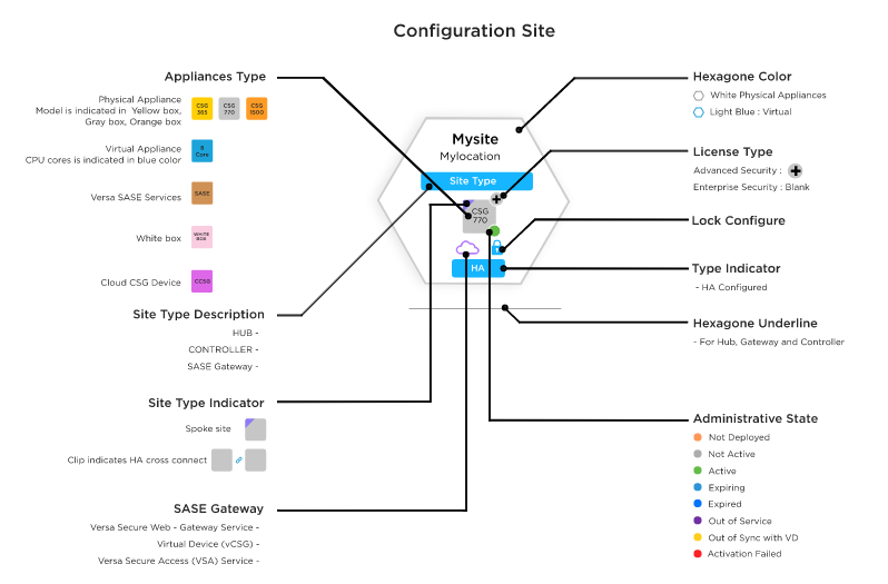
Map View
Move the toggle at the bottom of the Configure or Monitor dashboards to the right to switch from honeycomb to map view.

Easy Quick Picks
The Easy Quick Picks icon displays on many configuration screens. This feature repopulates a device configuration area with default values. It repopulates values for that configuration area only. For example, clicking Easy Quick Picks in the WiFi area only affects WiFi radio values. You can edit default configuration values using the Wrench icon in the bottom menu bar. See Default Configuration Values.
You cannot edit LAN settings in the default configuration, so clicking Easy Quick Picks in the LAN, Ethernet Ports, WiFi Ports, Port Forwarding, or Device IP Address reservation areas always resets to factory defaults. In the Steering area, the Easy Quick Picks icon is labeled Easy Steering Picks. In the Security area, it is labeled Easy Security Picks.
![]()
You can choose Easy Quick Picks in the following configuration areas:
- Steering
- Security
- WiFi
- LAN (Allows you to apply defaults to the following 4 areas with one click)
- Ethernet Ports
- WiFi Ports
- Port Forwarding
- Device IP Address Reservation
Create a New Customer from the Dashboard
An operator, store administrator, MSP, or reseller can create a new customer under them and then manage the customers.
To create a new customer:
- In the Organizations dashboard, click + New Customer.

- In the Add New Customer popup window, enter the following information.

Field Description First Name Enter the customer's first name. Last Name Enter the customer's last name. Email Enter an email address for the customer. Mobile Number Select the country code and enter the mobile number for the customer. Organization Name Enter the organization name. Two-Factor Authentication Click to enable two-factor authentication. Region Select a region for Versa Director. You can select multiple regions. Select Installation Methods - Versable
- URL ZTP
- GZTP
VD Customer Role Select the Versa Director customer role:
- TenantDashboardOperator
- TenantOperator
- TenantSecurityAdmin
- TenantSuperAdmin
Privileges Write Access—Grant permission to modify the selected network (WAN, LTE, WiFi, and LAN), security, and steering settings.
Read Access—Grant view permission:
- Versa Director—Grant access to the Live Monitoring dashboard in the Titan Portal.
- Analytics—Grant access to the Analytics and Director dashboards in Titan Portal.
- Audit Logs—Grant access to the Audit Logs dashboard in the Titan Portal.
- Click Submit.
Create a Notification
To create a maintenance notification:
- In the Organizations dashboard, select the organization. Then click Create Notification.

- In the Create Maintenance Notification popup window, enter the message and select the notification area.

- Click Send. A notification is sent to the user's mobile application. The user must be logged in to view the email message.
Add Devices
To add devices to an organization:
- In the Organizations dashboard, locate the organization in the grid, click the 3-dot icon, and then click Add Devices.

- In the Add Device Details popup window, select the hardware device:
- CSG
- cCSG
- vCSG
- Whitebox
- Cloud Gateway—Customer can purchase a private SASE gateway from cloud gateway through a store admin, MSP, or reseller.
- To add a CSG device, click CSG button, and then enter the following information.

Field Description Device Type Select the hardware device type CSG300, CSG700, or CSG1000
Region Choose a region:
- Americas & EMEA
- Asia
Hardware Add-on Click to display the hardware add-on menu, and then click the add-on. Wireless Interface Click to display the wireless interface menu, and then select wireless interface. Add-on NIC Click to display the add-on NIC menu, and then select the add-on. Software License Tier Select the software license:
- Advanced Security—Advanced security features
- Enterprise Security—Standard license
Subscription Duration Select the length of the subscription:
- 1 year
- 3 years
- 5 years
PO License Start Date Enter the purchase order license start date PO Number Enter the purchase order number Hardware Replacement Select the hardware replacement time:
- Next business day
- Same business day
Quantity Enter the number of hardware devices to order. - To add cCSG, vCSG, or Whitebox device, click the hardware button, and then enter the following information.

Field Description Device SKU Select the hardware device SKU:
- For cCSG devices:
- cCSG-L
- cCSG-M
- cCSG-XL
- For vCSG devices:
- vCSG-L
- vCSG-M
- vCSG-XL
- Whitebox
- Cloud Gateway—Customer can purchase a private SASE gateway from a cloud gateway using a store admin, MSP, or reseller.
Software License Tier Select the software license:
- Advanced Security—Advanced security features
- Enterprise Security—Standard license
Subscription Duration Select the length of the subscription:
- 1 year
- 3 years
- 5 years
PO License Start Date Enter the purchase order license start date PO Number Enter the purchase order number Quantity Enter the number of hardware devices to order. - For cCSG devices:
- Click Submit.
Prerequisites for Deploying cCSG Devices
This section describes the prerequisites for deploying a cCSG device on any cloud through the Versa Titan dashboard.
Before you begin, perform the following tasks on any cloud:
- Create a cloud server and mount to the internal gateway to reach the internet.
- In the cloud server deployed, install VOS 20.2.x, based on the Versa Director being used.
- Collect the LAN subnet information for the cloud server. Note that you must configure the cCSG LAN interfaces to match the cloud environment networks prior to deployment of the cCSG device.
Device Configuration and Activation Overview
This section provides a step-by-step procedure to configure and activate CSG300, CSG700, and CSG1000 series appliances in a non-HA configuration. To configure a CSG300, CSG700, and CSG1000 series appliances in an HA configuration, see Configure and Activate an HA Site. To configure virtual appliances using Amazon Web Services (AWS), see Configure a Branch in AWS.
To configure and activate a non-HA CSG300, CSG700, or CSG1000 series Versa appliance:
- Create a site using a software license. See Create a Site.
- Create a device configuration for the site. See Configure Device Networking, Configure Security, and Configure Steering.
The device configuration is stored in the Titan cloud portal when you save the configuration. You should configure WAN interfaces before deployment.
- Deploy the device configuration to the Versa Controller. See Deploy a Device Configuration.
Deploying a device configuration informs the Versa Controller that the configuration exists.
- Activate the appliance. See Activate an Appliance.
Activation validates the appliance, downloads its configuration, and allows traffic to begin flowing through it.
Note: After you activate a device, the configuration screen displays a Publish option in place of the Save option. Publish saves the configuration in the Titan cloud portal and the appliance. Procedures in this article use Save and Publish interchangeably.
After activation, you can display live status information, view device analytics, and monitor individual device status from the Live Monitoring, Analytics, and Monitor dashboards. See Manage Device Analytics, and Monitor Device Status.
Changes After Deployment or Activation
Some items cannot be changed after deployment or activation. In those cases, you must undeploy and redeploy the device configuration or deactivate (remove) and recreate the site. See Undeploy a Device Configuration and Remove a Site.
Note: You must wait 5 minutes after undeploying a device configuration before redeploying. Titan must sync internal data structures when you undeploy; if this process is not complete you will receive an error message when you attempt to activate the appliance.
The following configuration changes require you to undeploy then redeploy a device configuration. This applies to deployed configurations for both activated and unactivated devices:
- To add an additional WAN interface to the site—For example, if a system has only 1 WAN and you need to configure an additional WAN.
- To remove a WAN interface—For example, if a system is configured for 2 WAN ports and you need only 1 WAN port and do not choose to use the turn-off function of the port, then you must undeploy the configuration in order to remove the WAN port.
- To add an LTE interface to a device configuration.
- To change the site Topology type between any of the following:
- Full-mesh to Spoke
- Spoke to Full-mesh
- Full-mesh to Hub
- To change a site from being a single device to an HA pair.
- To change a WAN interface from internet to MPLS routing technique.
- To change a WAN interface from MPLS to internet routing technique.
- To enable or disable the gateway feature on a WAN interface.
- To enable PPPoE on an already-deployed WAN interface.
The following changes require you to deactivate (remove) then recreate a site:
- To change the appliance model for a location.
- To remove a site from the system.
Create a Site
This section provides a step-by-step procedure to create a site for CSG300 and CSG700 series appliances. To create an AWS site, see Configure a Branch in AWS. To create a site for an HA configuration, see Configure and Activate an HA Site.
Notes: You should choose the site topology type before saving the device configuration. To change the topology after saving, you must undeploy, change the topology, then redeploy the configuration. See Undeploy a Device Configuration.
You cannot change the license type after creating the site. You must remove and recreate the site using the correct license type.
To create a site for CSG300 and CSG700 series appliances:
- Click Configure in the left menu bar to open the Configure dashboard.
- Click one of the license package icons to display available license packages.
- CSG700 Series
- CSG300 Series

Licenses use the following naming conventions.
Acronym Description (blank) No WiFi and LTE WLA WiFi and LTE WLA-4GP WiFi and LTE and 4 copper GE PoE ports 2LA No WiFi, 2 LTE 2LA-4GP No WiFi, 2 LTE and 4x copper GE PoE ports
- Drag the license package onto the dashboard to add the site to the honeycomb.

The New Site: Configuration window displays.

- Enter information for the following fields.
Field Description Site Name Enter name of site. Address
Enter street address, zip code, city, state, and country.
Latitude and Longitude
Click the Auto Generate toggle to enable Latitude and Longitude coordinates automatically. Otherwise, enter coordinates manually (default). Device Group Select the device group that inherits the device configuration from another device. Topology Click Topology to configure the site role:
- Configure as Hub
- Configure as Hub Controller
- Configure as Spoke—There must be a hub already configured in order to configure a spoke.

HA Mode Click HA Mode to configure two appliances in an HA pair. See Configure and Activate an HA Site for details on configuring HA Mode. Service View device details.
- Serial Number—Enter the serial number of the CSG appliance.
- Click the down arrow next to Deploy to display the Save pop-up.

- Click Save.
Titan Portal saves the new site information in the Titan cloud and creates a honeycomb for the site.
Remove a Site
You can remove a site using the device-options card in the honeycomb or from the Inventory dashboard (see Inventory Actions). You can remove a site before deployment, after deployment, or after activation. For HA sites, you can use the device-options card for either of its 2 devices to remove the site.
To remove a site using its device-options card:
- From the Configure dashboard, hover on the device for the site to be removed.

- Click Remove on the options card for the device.
A confirmation message displays and the site is removed from the honeycomb. Device licenses used by the site are placed back in inventory.
Configure Device Networking
After you create a site, you create a configuration for the site devices. Device configurations include settings for Networking, Security, and Steering. This section describes the Network configuration settings including WiFi, LAN, and WAN.
Use the Configure Dashboard
To configure network settings from the Configure dashboard:
- Click Configure in the left menu bar to open the Configure dashboard.
- Hover over the site in the honeycomb to open the options card for the device.

- Click Configure in the Actions column of the device-options card to open the site information window.
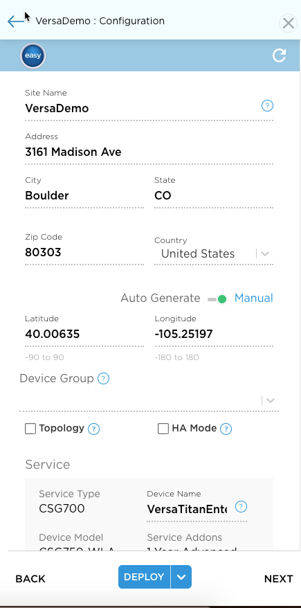
- Click Next to open the Configuration > Network screen.
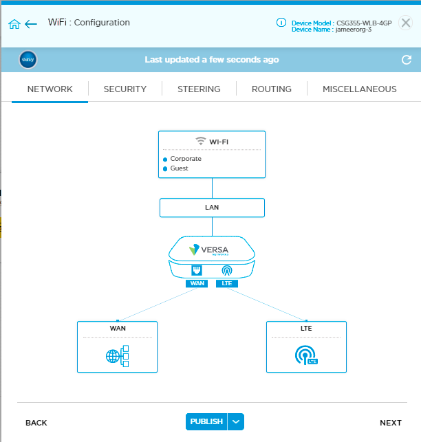
From the Configuration > Network screen, you can change configuration settings for the following configuration areas:
- WiFi—See Configure WiFi Radios
- LAN—See Configure LAN Connections
- WAN—See Configure WAN Connections
- LTE—See Configure LTE and APN Settings
Configure WiFi Radios
Versa appliances that support WiFi include WiFi radios, each radio connecting to a WiFi port. One radio connects to Corporate WiFi at port Wi-Fi-1, which accesses the corporate VPN (SD-WAN), and the other connects to Guest WiFi at port Wi-Fi-2, which accesses the internet. This section discusses configuring radio settings such as SSID and bandwidth. To configure IP addresses for devices connecting to these ports, see Configure WiFi Ports.
Configure Corporate WiFi
To configure Corporate WiFi settings:
- Click Configure in the left menu bar to open the Configure dashboard.
- Hover over the device in the honeycomb and click Configure to open the site information window.
- Click Next to open the Configuration > Network screen.
- Click the Wi-Fi box to open the Network > Wireless Networks screen.

The Network > Wireless Networks screen displays 2 WiFi radios. These are Corporate Wi-Fi, which uses an SSID of Titan-Corporate in this example, and Guest Wi-Fi, which uses an SSID of Titan-Guest.
- Click the current SSID for Corporate Wi-Fi to open the Network > Wireless Networks > Edit Network screen.
- Click the SSID and Passphrase fields to clear the current credentials, then enter new credentials. The WiFi SSID can be no more than 32 characters, and passwords must be between 8-25 characters.

- Choose a radio frequency from Dual Band, 2.4 GHz or 5 GHz.
- The Channel selection for Dual Band is set to Auto and cannot be changed. For 2.4 GHz and 5 GHz, the channel selection can be Auto or a Channel number.
- Click Add. This saves the change locally but does not save to the Titan cloud.
- Click Save to save the changes to the Titan cloud.
To assign IP addresses to the corporate WiFi port, Wi-Fi-1, see Configure WiFi Ports.
Configure Guest WiFi
To configure Guest WiFi settings:
- Click Configure in the left menu bar to open the Configure dashboard.
- Hover over the device in the honeycomb and click Configure to open the site information window.
- Click Next to open the Configuration > Network screen.
- Click the Wi-Fi box to open the Network > Wireless Networks screen.
- Click Guest in the Network > Wireless Networks window to open the Edit Network screen.

- Click in the SSID and Passphrase fields to clear the current credentials, then enter new credentials.
Bandwidth Control is automatically set to Auto. Access Control specifies that guests accessing this Wi-Fi are restricted to use the Internet only; guests do not have access to the company VPN. - Click the LTE toggle to enable or disable the use of LTE access by WiFi guests.
The radio channel is automatically set to Dual Band with a Channel Selection of Auto. - Choose the Dual Band, 2.4 GHz, or 5 GHz radio frequency.
The Channel selection for Dual Band is set to Auto and cannot be changed. For 2.4 GHz and 5 GHz, the channel selection can be Auto or a Channel number. - Click Add. This saves the change locally but does not save to the Titan cloud.
- Click Save to save the changes to the Titan cloud.
To configure IP addresses for the guest WiFi port, Wi-Fi-2, see Configure WiFi Ports.
Configure LAN Connections
On the Network LAN screen, you configure DHCP address pools, static routes, a DNS name server, and port forwarding. You can also reserve an IP address that is assigned by DHCP to a device. You configure these parameters for both Ethernet and WiFi ports.
To restore the default configuration, click Easy Quick Picks. Click the Refresh icon to update information on the screen.
To configure a LAN:
- Click Configure in the left menu bar to open the Configure dashboard.
- Hover over the device in the honeycomb and click Configure to open the site information window.
- Click Next to open the Configuration > Network screen.
- Click the LAN box to open the Network > LAN screen to configure the following:
- Ethernet Ports
- Wi-Fi Ports
- Port Forwarding
- Device IP Address Reservation

Configure Ethernet Ports
You can assign an IP address to an Ethernet port and configure DHCP addressing from the Ethernet Ports screen. The mapping from port number to LAN number varies based on the number of WAN ports.
Note: You should configure WANs before entering LAN information to ensure that the LAN configuration screen displays correct port numbers for the configuration.
To configure Ethernet ports on a LAN:
- Hover over the device in the honeycomb and click Configure to open the site information window.
- Click Next to open the Configuration > Network screen.
- Click the LAN box to open the Network > LAN screen.
- Click the Ethernet Ports box to open the Network > LAN > Ethernet Ports screen.

- Click the drop-down menu to the right of Easy Quick Picks to view a list of available ports and their corresponding LAN numbers.
- Select a LAN/port from the drop-down menu.
- Configure the following settings on the page:
- VLAN tagging
- HA cross-connect port
- DHCP settings
- Name servers
Configure VLAN Tagging
VLANs are used to enhance performance by reducing the need to send broadcasts and multicasts to unnecessary destinations. VLANs also ease network configuration by logically connecting devices without physically relocating those devices. You cannot change the VLAN configuration after it is added.
To configure VLAN tagging:
- Click Configure in the left menu bar to open the Configure dashboard.
- Hover over the device in the honeycomb and click Configure to open the site information window.
- Click Next to open the Configuration > Network screen.
- Click the LAN box to open the Network > LAN screen.
- Click the Ethernet Ports box to open the Network > LAN > Ethernet Ports screen.
- Select a port from the menu to the right of Easy Quick Picks.
- Click the VLAN Tagging toggle to turn on VLAN configuration options.

Enter information for the following fields.
Field Description VLAN ID
Enter the VLAN ID. IP Address/Mask
Enter a valid IP prefix and length. The length must be in /25 CIDR subnet mask notation, for example, 172.16.4.0/25. - Click Add VLAN to save the changes.
- Click Save to save the configuration.
Configure HA Cross-Connect Port
The cross-connect link is a physical connection between the redundant CPE devices that emulates the missing transport domain in a branch and provides redundancy to the attached clients. The cross-connect port is used in HA deployments and user must allocate one port on each CPEs for the cross-connect port. You can select any one of the LAN ports as a cross-connect port from the available list of LAN ports. You configure HA cross-connect port on the primary device and cannot delete the cross-connect port from the primary or secondary device.
You must enable the HA cross-connect port in device save mode. After you deploy and activate the device, you cannot change the cross-connect port and also it is not displayed in the LAN port list.
To configure the HA cross-connect port:
- Click Configure in the left menu bar to open the Configure dashboard.
- Hover over the device in the HA honeycomb and click Configure to open the site information window.
- Click Next to open the Configuration > Network screen.
- Click the LAN box to open the Network > LAN screen.
- Click the Ethernet Ports box to open the Network > LAN > Ethernet Ports screen.
- Select a port from the menu to the right of Quick Picks.

- Click the HA Cross Connect Port toggle to turn on HA cross-connect port.
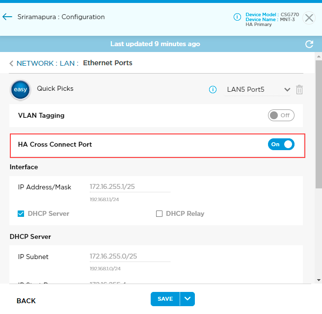
- Click Save.
Configure DHCP Settings
Titan devices include the Dynamic Host Configuration Protocol (DHCP) server and the DHCP relay-agent software. The DHCP server implementation assigns and manages IP addresses from specified address pools within the device to DHCP clients. The DHCP server can be configured to assign additional parameters, such as the IP address of the Domain Name System (DNS) server and the default device. You can also set the IP address of a DHCP server to which the DHCP relay agent forwards client requests.
To configure DHCP settings:
- Hover over the device in the honeycomb and click Configure to open the site information window.
- Click Next to open the Configuration > Network screen.
- Click the LAN box to open the Network > LAN screen.
- Click the Ethernet Ports box to open the Network > LAN > Ethernet Ports screen.
- Select a port from the menu to the right of Quick Picks.
- Click the DHCP Server checkbox to activate configuration fields on the screen.

- Enter information for the following fields.
Field Description IP Subnet Enter a valid IP prefix and length. The length must be /25 CIDR subnet mask notation, for example, 172.16.4.0/25. IP Start Range
Enter the IP address at the beginning of the DHCP address pool. IP End Range
Enter the IP address at the end of the DHCP address pool. Name Servers By default, a primary and secondary DNS name server is configured automatically. - Click Save to save the settings.
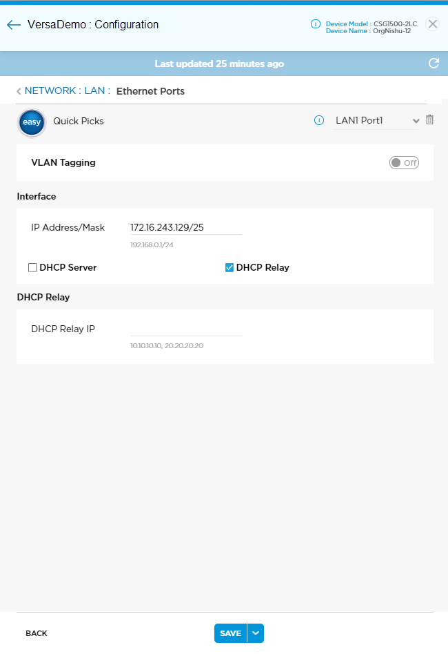
DHCP Relay
- Select the DHCP Relay option.
- Enter the IP address of the DHCP relay agent. You can enter multiple IP addresses separated by a comma.
DHCP Client Options
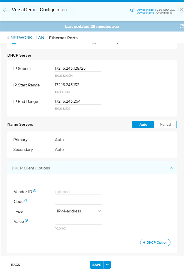
You can configure DHCP Client Options on a per-LAN-interface and per-VLAN basis for Versa Titan sites. Available options are Option 43, Option 66, and Option 42, with corresponding support for Boolean, IPv4 address, String, and FQDN type fields.
To configure DHCP client options:
- From the Network > LAN > Ethernet Ports window, click DHCP Client Options to open the DHCP Client Options window.
- Enter information for the following fields.
Field Description Vendor ID (optional) Enter vendor ID.
Code Enter DHCP option code. Valid options are 42 (NTP server), 43 (vendor specific), or 66 (TFTP server). Type Enter data type of the value. These are the system-defined types:
- boolean
- fqdn
- ipv4-address
- string
Value Enter a value for the chosen option code.
- Click + DHCP Option to save the option to the DHCP screen. The new option displays on the screen.

- Click the Trash icon to delete a DHCP option.
- Click Save to save the changes to the Titan cloud before leaving the Ethernet Ports screen.
Edit LAN Interfaces on an Active Device
After you configure LAN interfaces and deploy or activate the device, you can make the following changes to a LAN interface:
- Add or remove a WAN, LAN, or LTE interface.
- Switch the gateway on or off.
- Update the transport from internet to MPLS, or vice versa.
- Enable or disable PPPoE.
To make changes to a LAN interface, you must first lock the device using the enable lock mode option in the honeycomb view in the Titan Portal home screen. The lock icon displays only if the device is deployed. A blue lock icon indicates that the device is unlocked, and a red lock icon indicates that the device is locked. After you publish the changes to Titan Portal, you must unlock the device.
To edit LAN interfaces:
- Click Configure in the left menu bar to open the Configure dashboard.

- Click the
 icon in the honeycomb to lock the device.
 - Enter the reason for lock in the Enable lock mode popup window and click Yes.

- Hover over the device in the honeycomb and click Configure to open the site information window.
- Click Next to open the Configuration > Network screen.
- Click the LAN box to open the Network > LAN screen.
- Click the Ethernet Ports box to open the Network > LAN > Ethernet Ports screen.

- Click the drop-down menu to the right of Easy Quick Picks to view a list of available ports and their corresponding LAN numbers.
- Select a LAN/port from the drop-down menu.
- Click the
 icon to delete the selected LAN.
 - Click +LAN in the drop-down menu, select available ports, and then click Continue to add a new LAN port.

The +LAN is displayed only if number of ports are available to configure in the LAN.
- Click the
- Click Publish and then click Continue.

- Click the
 icon in the honeycomb to unlock the device and click Yes.

Configure WiFi Ports
You can assign a range of IP addresses to each WiFi port. To configure WiFi radio settings, such as SSID, for these ports see Configure WiFi Radios.
To configure WiFi port settings:
- Hover over the device in the honeycomb and click Configure to open the site information window.
- Click Next to open the Configuration > Network screen.
- Click the LAN box to open the Network > LAN screen.
- Click the Wi-Fi Ports box to open the Network > LAN > Wi-Fi Ports screen.

- Select the DHCP Server checkbox. Enter information for the following fields:
Field Description IP Subnet Enter a valid IP prefix and length. The length must be /25 CIDR subnet mask notation, for example, 172.16.4.0/25. IP Start Range
Enter the IP address at the beginning of the DHCP address pool. IP End Range
Enter the IP address at the end of the DHCP address pool. Name Servers By default, primary and secondary DNS name servers are configured automatically. To change values, click Manual then enter a valid primary and secondary value. - Click Save to save the settings.
Configure Port Forwarding
NAT port forwarding, also called port mapping, redirects packets from one address and port number pair to another while the packets are traversing the Titan device. You configure port forwarding rules to allow incoming traffic to reach its destination in the LAN. You should configure WAN ports before configuring port forwarding. Only configured WAN interfaces are available in the Port Forwarding screen. Port forwarding is not enabled by default; you must configure a rule. When a rule is created, it is automatically enabled.
To configure a port forwarding rule:
- Click Configure in the left menu bar to open the Configure dashboard.
- Hover over the device in the honeycomb and click Configure to open the site information window.
- Click Next to open the Configuration > Network screen.
- Click the LAN box to open the Network > LAN screen.

- Click the Port Forwarding box to open the Network > LAN > Port Forwarding screen.
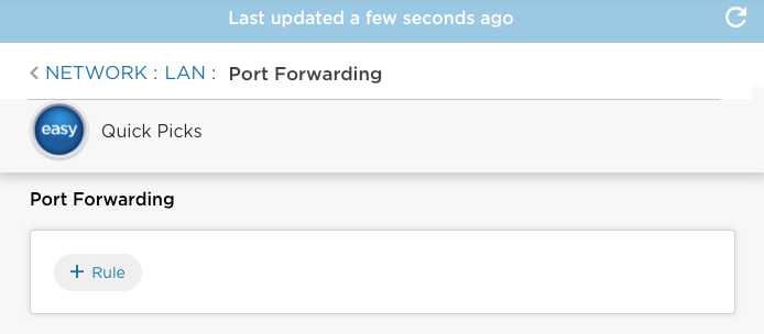
- Click + Rule on the Network > LAN > Port Forwarding screen to display the Add Rule screen and enter information for the following fields.
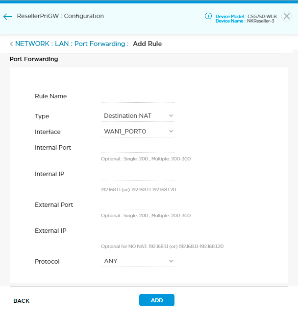
Field Description Rule Name Enter a name for the rule. Type Choose the address translation method:
- Destination NAT
- Source NAT
- Static NAT
- No NAT
Interface Choose a WAN interface. The drop-down menu lists only configured WAN interfaces.
Internal Port Enter a port number. You can configure a single port number or a range of port numbers, for example, 200 or 200–300. The type of internal port you configure (single or range) must be the same as the type of external port. For static NAT, the internal port option is not applicable. Internal IP Enter an internal IP address or IP address range. The IP addresses must fall within the start and end IP address range of any of the LAN ports. The internal IP type (single or range) must be the same as the external IP type. Internal and external IP ranges must match SNAT rules. External Port Enter a port number. You can configure a single port number or a range of port numbers, for example, 2100 or 200-300. The type of external port you configure (single or range) must be the same as the type of internal port. For static NAT, the external port option is not applicable. External IP Enter an external IP address or IP address range. The IP addresses must fall within the start and end IP address range of any of the LAN ports. The external IP type (single or range) must be the same as the internal IP type. Internal and external IP ranges must match SNAT rules. Protocol Select Any, TCP, or UDP. - Click Add. This adds the rule to the screen but does not save to the Titan cloud.

- Click Save to save the new rule to the Titan cloud.
To update a rule:
- Click the rule name to edit the rule, or click X to delete the rule.
- Click Save to update the Titan cloud.
To delete all rules:
- Click Easy Quick Picks. This deletes all port forwarding rules since the default configuration contains none.
- Click OK in the pop-up window.
- Click Save to update the Titan cloud.
Reserve an IP Address for a Device
To permanently assign an IP address to a device, you can reserve a specific address that is part of the interface's IP subnet. To reserve an IP address for a device, you can either add a new device by creating a rule or click the Add Devices icon to add devices that are already connected.
To reserve a device IP address for a device:
- Click Configure in the left menu bar to open the Configure dashboard.
- Hover over the device in the honeycomb and click Configure to open the site information window.
- Click Next to open the Configuration > Network screen.
- Click the LAN box to open the Network > LAN screen.

- Click the Device IP Address Reservation box to open the Device IP Address Reservation screen.

- Click + Rule on the Network > LAN > Device IP Address Reservation screen to display the Add Rule screen.
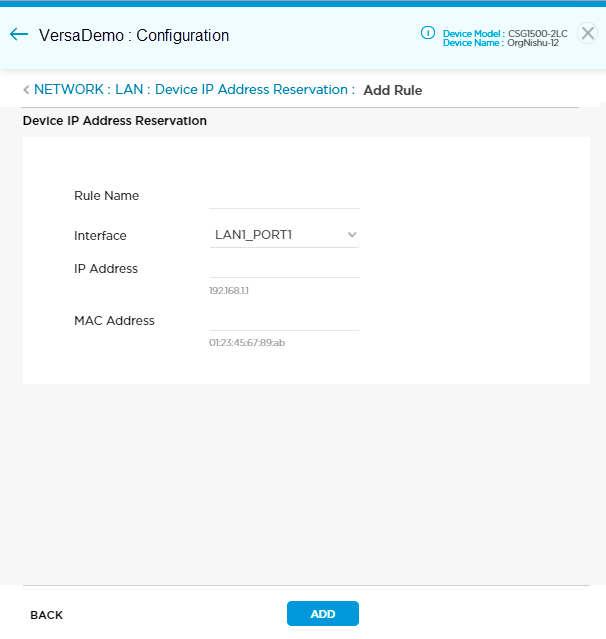
- Configure settings for the following fields.
Field Description Rule Name Enter a name for the rule. Interface Select an interface name. IP Address Enter the IP address to reserve. This IP address must be part of the interface's IP subnet. MAC Address Enter the MAC address of the device for which you are reserving the IP address. - Click Add to add the rule. This adds the rule to the screen but does not save to the Titan cloud.

- Click Save to save the new rule to the Titan cloud.
To update a rule:
- Click the rule name to edit the rule, or click X to delete the rule.
- Click Save to update the Titan cloud.
To delete all rules:
- Click Easy Quick Picks. This deletes all IP address reservation rules since the default configuration contains none.
- Click OK in the pop-up window.
- Click Save to update the Titan cloud.
Configure WAN Connections
This section describes how to change WAN settings. The WAN configuration affects LAN port numbering, so you should configure WANs first. You must configure WAN interfaces before a device is deployed.
Note: You should configure WAN interfaces before saving the device configuration, including the following settings:
- Adding or deleting WAN interfaces
- Choosing MPLS or internet routing technique
- Enabling the gateway feature
- Enabling PPPoE protocol
- Enabling HA Mode
To change these settings saving, you must undeploy, change the settings, then redeploy the configuration. See Undeploy a Device Configuration.
To configure a WAN:
- Click Configure in the left menu bar to open the Configure dashboard.
- Hover over the device in the honeycomb and click Configure to open the site information window.
- Click Next to open the Configuration > Network screen.
- Click the WAN icon to open the Network > WAN screen.

- Click WAN1-Port0 to add one or multiple WAN interfaces.

- If needed, click the + WAN icon in the drop-down menu to add a WAN. To delete the highest-numbered WAN, select it from the drop-down and then click the trash icon.
- Select the WAN to be configured from the drop-down menu. The WAN connection at appliance port 0 is WAN1, port 1 is WAN2, etc.
- Use the toggle switch to switch a WAN interface on or off.
- Click a circuit role:
- Primary—The interface that sends SD-WAN and DIA traffic.
- Hot Standby—When used as a hot standby, you can create rules to steer traffic on the interface. Titan only sends DIA traffic to the interface if the primary interface is down.
- Choose the link mode. Default link mode is set to Auto. Link mode can also be set to half-duplex or full-duplex.
- Choose the link speed. Link speed can be set to 10 Mbps, 100 Mbps, or 1 Gbps. For link speed above 1 Gbps, use the default value (Auto).
- Click On or Off to enable or disable the interface as a gateway. After you enable an interface to be a gateway, the branch becomes a gateway and a sends default route to its peer branch or branches. You can set up a gateway configuration in two topologies:
- Full mesh—All peer devices receive a default route from the device that is set as the gateway. Typically, this topology is not used.
- Hub (in hub-and-spoke topology)—A gateway is used in a hub-and-spoke topology to allow spokes to route traffic through the hub. To deploy and create a spoke site, you must first create a hub on which a gateway is enabled and deployed. Enabling a gateway as a hub allows you to define traffic-steering rules and policies for having the spoke perform local internet breakout for some traffic while sending all other traffic to the hub gateway.
- Choose the transport domain to be Internet or MPLS, depending on the WAN connection.
- Uplink bandwidth refers to the traffic from the branch to the outside network. Enter the actual bandwidth purchased from the service provider.
- Downlink bandwidth refers to the traffic from the outside network to the branch. Enter the actual bandwidth purchased from the service provider.
- For a hub–controller topology, use the toggle switch to switch the Hub Controller Staging on or off, and then select the staging pool size.
- Choose the tunnel type using the Tunnel Selection drop-down list:
- Globe icon—Internet only
- Hub icon—VPN only
- Combined Globe and Hub icon—SD-WAN and Internet (DIA) Split Tunnel
Note: Spoke sites must have at least one WAN set to VPN only. This configures the spoke to accept and use the default route propagated by the Hub gateway for centralized internet access. Versa recommends that you set only one WAN interface as VPN-only for the spoke. - Enter the VLAN ID for the interface.
- Click the Network Address toggle to select DHCP or Static.
- For a static network, enter a valid IP address and gateway address.
- For a static network, enter the primary and secondary IP addresses for the DNS servers.
- If the device is configured in a hub–controller topology, click the NATeD toggle to enable NAT firewall, and then enter the public IP address of the firewall WAN interface. Note that for a hub–controller topology, you cannot configure DHCP.
- Click Save to save the settings.
Edit WAN or LTE Interfaces in an Active Device
After you configure WAN interfaces and deploy or activate the device, you can make the following changes to a WAN or LTE interface:
- Add or remove a WAN, LAN, or LTE interface.
- Switch gateway ON or OFF.
- Update the transport from internet to MPLS or vice versa.
- Enable or disable PPPoE.
To make changes to a WAN or LTE interface, you must first lock the device using the enable lock mode option in the honeycomb view in the Titan Portal home screen. The lock icon displays only if the device is deployed. A blue lock icon indicates that the device is unlocked, and a red red lock icon indicates that the device is locked. After you publish the changes to Titan Portal, you must unlock the device.
To edit WAN interfaces:
- Click Configure in the left menu bar to open the Configure dashboard.

- Click the
 icon in the honeycomb to lock the device.
 - Enter a reason for enabling lock mode in the Enable lock mode popup window and click Yes.

- Hover over the device in the honeycomb and click Configure to open the site information window.
- Click Next to open the Configuration > Network screen.
- Click the WAN box to open the Network > WAN screen.
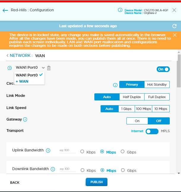
- Click WAN1-Port0 to display a list of available ports and their corresponding WAN numbers.
- Select a WAN port.
- Click the
 icon to delete the selected WAN.
 - Click the + WAN icon to add a WAN interface. The + WAN icon displays only if WAN ports are available to be configured.

- Click the
- Click Publish and then click Continue.

- Click the
 icon in the honeycomb to unlock the device and then click Yes.

Configure the IPsec VPN Setting
You use the IPsec VPN option to build an IPsec tunnel to other appliances or applications. Titan Portal then adds the tunnel name to the drop-down menus for WAN static IP routes, steering rules, and firewall rules for route-based IPsec profiles. For policy- and rule-based VPNs, no zone/menu options are available in static, steering, and security rules. Tunnels use preshared key (PSK) authentication and are built using IKEv1, IKEv2, or both IKEv1 or IKEv2. If you configure the tunnel using IKEv1, ensure that the shared key value for the local authentication and peer authentication are the same.
You can click + Add to configure multiple tunnels.
Note: You must add a static route to enable routing over this IPsec tunnel.
To configure an IPsec tunnel:
- From the Network > WAN screen, click the IPsec VPN option to display the IPsec VPN fields.

- In the IPsec VPN option drop-down, enter information for the following fields.
Field Description Name Enter IPsec tunnel name. Titan Portal adds the tunnel name to the IPsec drop-down menu in the Static IP Route screen. Redistribute Click to make the IPsec tunnel eligible for redistribution into the VPN network when thee tunnel is used as the next hop for a static route. Peer Type Enter format for the peer value: hostname, fully qualified domain name (FQDN), or IP address. Peer Type Value Enter peer value using the format selected in peer type. Local Auth - Auth Type
Displays the Auth type (PSK). - Identity Type
Enter format for the identity type value: email, FQDN, or IP address. - Identity Type Value
Enter value in the format selected in identity type. - Shared Key
Enter preshared key. Peer Auth - Auth Type
Displays the Auth type (PSK). - Identity Type
Enter format for the identity type value: email, FQDN, or IP address. - Identity Type Value
Enter value in the format selected in identity type. - Shared Key
Enter the preshared key. IKE Version Select the IKE version:
- IKEv1
- IKEv2
- IKEv1 or IKEv2
- Hash Algorithm
Select the hash algorithms to use:
- MD5—MD5 Message Digest Algorithm
- SHA-1—Secure Hash Algorithm 1 with 160-bit digest
- SHA-256—Secure Hash Algorithm 2 with 256-bit digest
- SHA-384—Secure Hash Algorithm 2 with 384-bit digest
- SHA-512—Secure Hash Algorithm 2 with 512-bit digest
- Encryption
Select the encryption algorithms to use:
- 3DES—Triple DES encryption algorithm
- AES 128—AES CBC Encryption Algorithm with 128-bit key
- AES 256—AES CBC Encryption Algorithm with 256-bit key
- DH Group
Select the Diffie-Hellman group to use:
- Diffie-Hellman Group 1—768-bit modulus
- Diffie-Hellman Group 2—1024-bit modulus
- Diffie-Hellman Group 5—1536-bit modulus
- Diffie-Hellman Group 14—2048-bit modulus
- Diffie-Hellman Group 15—3072-bit modulus
- Diffie-Hellman Group 16—4096-bit modulus
- Diffie-Hellman Group 19—256-bit elliptic curve
- Diffie-Hellman Group 20—384-bit elliptic curve
- Diffie-Hellman Group 21—521-bit elliptic curve
- Diffie-Hellman Group 25—192-bit elliptic curve
- Diffie-Hellman Group 26—224-bit elliptic curve
- IKE Rekey Time
Enter the time interval for how often to regenerate the IKE key.
Range: 3600 through 28800 seconds
Default: 3600 secondsIPsec Transforms Specify the IPsec transform and Diffie-Hellman group. - Hash Algorithm
Select the hash algorithms to use:
- MD5—MD5 Message Digest Algorithm
- SHA-1—Secure Hash Algorithm 1 with 160-bit digest
- SHA-256—Secure Hash Algorithm 2 with 256-bit digest
- SHA-384—Secure Hash Algorithm 2 with 384-bit digest
- SHA-512—Secure Hash Algorithm 2 with 512-bit digest
- XCBC—Extended Cypher Block Chaining
- Encryption
Select the encryption algorithm to use:
- 3DES—Triple DES encryption algorithm
- AES128—AES CBC encryption algorithm with 128-bit key
- AES128-CTR—AES counter mode encryption algorithm with 128-bit key
- AES128-GCM—AES GCM encryption algorithm with 128-bit key
- AES256—AES CBC encryption algorithm with 256-bit key
- AES256-GCM—AES GCM encryption algorithm with 128-bit key
- NULL
- Perfect Forward Secrecy Group
Select the Diffie-Hellman groups to use for PFS:
- Diffie-Hellman Group 1—768-bit modulus
- Diffie-Hellman Group 2—1024-bit modulus.
- Diffie-Hellman Group 5—1536-bit modulus
- Diffie-Hellman Group 14—2048-bit modulus
- Diffie-Hellman Group 15—3072-bit modulus
- Diffie-Hellman Group 16—4096-bit modulus
- Diffie-Hellman Group 19—256-bit elliptic curve
- Diffie-Hellman Group 20—384-bit elliptic curve
- Diffie-Hellman Group 21—521-bit elliptic curve
- Diffie-Hellman Group 25—192-bit elliptic curve
- Diffie-Hellman Group 26—224-bit elliptic curve
- No PFS
- IPsec Rekey Time
Enter the time interval for how often to regenerate the IPsec key.
>Range: 3600 through 28800 seconds
Default: 3600 secondsTunnel Network (Route-Based Only) Use a route-based tunnel configuration. - Tunnel IP Local Address
Enter the IP address of the local tunnel interface in CIDR format. If you do not specify a value, the IP address is automatically generated. - Tunnel IP Remote Address
Enter the IP address of the remote tunnel interface. If you do not specify a value, the IP address is automatically generated. Policy-Based VPN Click the Policy-Based VPN toggle to turn on VPN policies configuration options. If you select this option, click the
 Add Rule icon to add a policy. You can configure a tunnel either using route-based or policy-based options.
In the Policy-Based VPN popup window, enter information for the following fields.
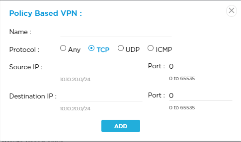
- Name—Enter a name for the policy.
- Protocol—Select a protocol:
- Any
- ICMP
- TCP
- UDP
- Source IP—Enter the IPv4 source address or prefix.
- Port—Enter the source port number.
- Destination IP—Enter the IPv4 destination address or prefix.
- Port—Enter the destination port number.
- Click Add.
- Click +Add IPsec Profile. This saves the tunnel to the IPsec VPN screen but not the Titan cloud.

Use the trash icon to delete a tunnel or the pencil icon to edit a tunnel. Click the Eye icon to display tunnel details.
 - Click Save to save the changes to the Titan cloud. Once saved, Titan Portal adds the IPsec tunnel name to the drop-down menus for WAN static IP routes, steering rules, and firewall rules. See Manage Firewall Policies, SD-WAN Steering, and Internet Steering.
Configure PPPoE Settings
Point-to-Point Protocol over Ethernet (PPPoE) is used with DSL services in which individual users connect to a DSL modem over Ethernet. The PPPoE username and password configured on the WAN interface must match settings on the WAN server to be active; otherwise, PPPoE is inactive. You cannot remove or add a new PPPoE instance once a device has been deployed but you can edit the PPPoE username and password at any time.
When PPPoE is active, you can monitor status within the WAN interface from the Monitoring > Network screen. You can also perform a speed test and view steering options from the Speed Test and Steering screens.
Versa Titan supports xDSL interface on CSG355 and CSG365 appliances. You must upgrade these appliances to Versa Operating SystemTM VOSTM (VOS) Release 21.2.1 or later to get the xDSL option displayed in your Versa Titan Portal. GZTP and WiFi are not available for xDSL activation with static IP and PPPoE. Use Versable activation with mobile app to activate the device when xDSL with static IP and PPPoE is configured. You can configure and enable PPPoE only on WAN1 and WAN2 ports before you deploy the device. You use Titan Portal to configure and deploy xDSL device. Titan Mobile can be used only for xDSL device activation and monitoring the status.
To configure PPPoE:
- Click Configure in the left menu bar to open the Configure dashboard.
- Hover over the device in the honeycomb and click Configure to open the site information window.
- Click Next to open the Configuration > Network screen.
- Click the WAN icon and select the WAN interface.
- Click the PPPoE tab and switch the PPPoE Status toggle to on.

- Select an interface type.
- Ethernet
- xDSL
- Select a multiplexing type:
- LLC
- VC-MUX
- Choose an instance type from the drop-down list:
- Internet Only—Traffic is directed to DIA only.
- SD-WAN Only—Traffic is directed to the SD-WAN VPN only.
- SD-WAN and Internet (DIA) Split Tunnel—VPN traffic is directed to the SD-WAN VPN. Internet traffic is directed to DIA.
- Enter the username and password in the fields provided.
- Enter the Service Name provided by DSL provider.
- Enter the name of the access concentrator. The access concentrator name on both the client and the server must be the same to establish the PPPoE session.
- Enter the virtual path identifier.
Range: 0 through 256 - Enter the Virtual channel identifier.
Range: 32 through 65535; 0 through 31 are reserved - Enter the VLAN ID configured for the xDSL line.
- Click Save to save the settings.
Configure LTE and APN Settings
You can configure Long-Term Evolution (LTE) wireless broadband services on appliances that support LTE. LTE wireless functionality is useful when a branch does not have a wired connection to the internet.
An access point name (APN) establishes a connection to the gateway between the carrier's network and the internet. Your service provider may require specific setting for the connection, and you can enter these APN details manually.
Note: You should configure LTE interfaces before saving the device configuration. To change add or remove an LTE interface after saving you must undeploy, change the settings, then redeploy the configuration. See Undeploy a Device Configuration.
To view LTE settings and update APN settings:
- Click Configure in the left menu bar to open the Configure dashboard.
- Hover over the device in the honeycomb and click Configure to open the site information window.
- Click Next to open the Configuration > Network screen.
- Click the LTE box to open the Network: LTE Screen.

- Use the drop-down menu to select an existing LTE interface, or select +LTE to add an additional interface (up to 4 total).
- Switch the LTE interface on or off using the toggle.
- Click a circuit role:
- Primary—The interface that sends SD-WAN and DIA traffic.
- Hot Standby—When used as a hot standby, you can create rules to steer traffic on the interface. Titan only sends DIA traffic to the interface if the primary interface is down.
- Cold Standby—The interface is operationally down. No traffic flows on the interface until the primary interface is detected as down.
- Switch the toggle to turn the LTE gateway configuration on or off. You must turn this feature on before the configuration is deployed.
- Enter the maximum transmission unit (MTU). Range: 72 through 9000 bytes.
- Enter the actual bandwidth purchased from the service provider. Uplink bandwidth refers to the traffic from the branch to the outside network.
- Enter the actual bandwidth purchased from the service provider. Downlink bandwidth refers to the traffic from the outside network to the branch.
- Choose the type of tunnel using the Tunnel Selection drop-down list:
- Globe icon—Internet only
- Hub icon—VPN only
- Combined Globe and Hub icon—SD-WAN and Internet (DIA) Split Tunnel
- The network address and name servers are set to Auto and cannot be changed.
- Click Manual to configure the APN manually. APN is set to Auto by default. Enter information for the following fields.

Field Description APN Enter the access point name (APN) that you received from your service provider. PIN For a USB modem that is locked with a PIN, enter a PIN number. Username Enter the username provided by the service provider to use to access the wireless WAN. This username is used when a CDMA modem prompts for a username. Password Enter the password provided by the service provider to access the wireless WAN. This password is used when a CDMA modem prompts for a password. Click Show/Hide to view the new password. - Click Save to save the settings.
- Verify the settings from the Monitoring screen any time you change between Manual or Auto.
Configure Security
From the Security tab you can configure firewall policies, secure traffic flow based on URL, set antivirus strength, tune the intrusion prevention system (IPS), and TLS decryption. You can customize security settings before or after you activate the device. TLS decryption is supported only when you enable advanced security settings. That is, you must enable firewall, security profile, antivirus, and intrusion prevention system to configure TLS decryption.
To configure security settings:
- Click Configure in the left menu bar to open the Configure dashboard.
- Hover over the device in the honeycomb and click Configure to open the site information window.
- Click Next to open the Configuration > Network screen.
- Click the Security tab.

- Click Security Policy to open the Security settings screen.

Customize the following settings on the Configure > Security screen:
- Firewall Policies—Set firewall rules
- Security Profile Definition—Categorize URLs, configure reputation, antivirus, and intrusion prevention,
Manage Firewall Policies
The Titan portal is preconfigured with default firewall rules. You cannot modify the default rule but you can add a new rule.
To configure firewall settings:
- In the Firewall Policies section, click Firewall Rules to open the Configuration > Security > Firewall Rules screen.
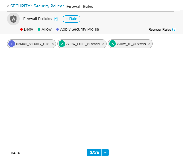
Each rule displays a numbered circle indicating its position in the rule set. Circle color indicates whether a rule denies (red) or allows (green) traffic, or applies one of the profiles listed in the Security Profile Definition section (purple).
- If needed, click Reorder Rules to enter rule reorder mode.
- To change a rule order, click the colored circle and drag the rule to a different spot in the rule set. The rule numbers are updated automatically.
- Click Publish Reordered Rules to save the changes to the Titan cloud.
- If needed, click + Rule to add a new firewall rule.

- Configure settings on the screen:
| Field | Description |
|---|---|
| Rule Name | Enter a name for the rule. |
| Match Criteria | There are 4 types of match criteria. Click Protocol, Address, Hostname, or Application to add details for that criteria type. Match criteria details are listed in the Match Criteria for Rules section. |
| Scope | |
| Source Zone |
Click the down arrow in the Please Select field. A pop-up window displays the configured interfaces and tunnels. Choose a source zone then click Continue. To create a tunnel, see IPsec VPN. |
| Arrow |
Choose a |
| Destination Zone |
Click the down arrow in the Please Select field. A pop-up window displays the configured interfaces and tunnels. Choose a destination zone then click Continue. To create a tunnel, see IPsec VPN. |
| Action |
Choose Deny, Allow, or Apply Security Profile. When you click Apply Security Profile, a pop-up window displays. Choose a level of security for each of the following:
Security levels can be Low, Standard, or Advanced. |
- Click Add to save the changes. The new rule appears on the Firewall Rules screen.
- Click Publish to save all firewall policies.
Click X in the icon to remove a rule, then click Publish.
Click the following on the Security > Firewall Rules: New Rules screen to view default firewall rules:
- Allow_From_SDWAN
- Allow_To_SDWAN
- Default_Security_Rule
- Default_security_wifi (if the device supports WiFi)
Note that you cannot edit a default Rule.

Create a Firewall Rule for SASE Gateway
To create a firewall rule for Secure Access Service Edge (SASE) gateway:
- In the Firewall Policies section, click Firewall Rules to open the Configuration > Security > Firewall Rules screen.

Each rule displays a numbered circle indicating its position in the rule set. The color of the circle indicates whether a rule denies traffic (red), allows traffic (green), or applies one of the profiles listed in the Security Profile Definition section (purple). - If needed, click Reorder Rules to enter rule reorder mode.
- To change a rule order, click the colored circle and drag the rule to a different spot in the rule set. The rule numbers are updated automatically.
- Click Publish Reordered Rules to save the changes to the Titan cloud.
- Click +Rule to add a new firewall rule.

- Configure settings on the screen:
| Field | Description |
|---|---|
| Rule Name | Enter a name for the rule. |
| Match Criteria | There are 4 types of match criteria. Click Protocol, Address, Hostname, or Application to add details for a criteria type. See Match Criteria for Rules for match criteria details |
|
Click the down arrow in the Please select drop-down list to select the protocol.
|
|
| Scope | |
| Source Zone |
Click the down arrow in the Please Select drop-down list. A pop-up window displays the zones that classify the traffic flows coming to the gateway from various sources. Select a source zone, and then click Continue.
|
| Arrow |
Choose a |
| Destination Zone |
Click the down arrow in the Please Select drop-down list. A pop-up window displays the zones that classify the traffic flows coming to the gateway from various sources. Select a destination zone, and then click Continue.
|
| Action |
Choose Deny, Allow, or Apply Security Profile. When you click Apply Security Profile, a pop-up window displays. Choose URLs and select a security level:
|
-
- Click Publish to save all firewall policies.
Click X in the icon to remove a rule, then click Publish.
Manage Security Profile Definitions
Security profile definitions contain 3 components:
- URL settings, including a URL blacklist and URL whitelist
- Antivirus settings
- Intrusion Prevention System (IPS) settings
You can manage individual components from the Security screen. You can enable or disable all components with one click from the Inventory menu. See Manage Device License Inventory.
To manage the security profile components:
- From the Configuration > Security tab, click the Security Policy to open the Security settings screen.

- Slide the toggle to turn individual security components on or off.
Configure a URL Blacklist
Add websites to be blocked on the network so that users cannot access the sites. Add multiple websites by separating them with a comma.
To add URLs to a Blacklist:
- Click Configure in the left menu bar to open the Configure dashboard.
- Hover over the device in the honeycomb and click Configure to open the site information window.
- Click Next to open the Configuration > Network screen.
- Click the Security tab.
- In the Security Profile Definition section, click Blacklisted URLs to open the Configuration > Security > Blacklisted URLs screen.

- Enter a single URL or enter multiple URLs separated by a comma.
- Click + Add URL to add URLs to the Blacklist.
- Click Publish to save the settings.
To delete URLs from the list, click the X next to the URL.
Configure a URL Whitelist
Add websites allowed on the network, even if blocked by other settings. Add multiple websites by separating them with a comma.
To add URLs to the Whitelist:
- Click Configure in the left menu bar to open the Configure dashboard.
- Hover over the device in the honeycomb and click Configure to open the site information window.
- Click Next to open the Configuration > Network screen.
- Click the Security tab.
- In the Security Profile Definition section, click Whitelisted URLs to open the Configuration > Security > Whitelisted URLs screen.

- Enter a single URL or enter multiple URLs separated by a comma.
- Click + Add URL to add URLs to the Whitelist.
- Click Publish to save the settings.
To delete URLs from the list, click the X next to the URL.
Configure URL Categories
To set a category filter for types of URLs to allow or block:
- Click Configure in the left menu bar to open the Configure dashboard.
- Hover over the device in the honeycomb and click Configure to open the site information window.
- Click Next to open the Configuration > Network screen.
- Click the Security tab.
- Click a Category level to open the configuration screen for that level:
- Low
- Standard
- Advanced

- Click to select the categories to Block or Alert & Confirm.
- Click Publish to save the settings.
Configure IP Reputation Filtering
To set a reputation filter for types of URLs to allow or block:
- Click Configure in the left menu bar to open the Configure dashboard.
- Hover over the device in the honeycomb and click Configure to open the site information window.
- Click Next to open the Configuration > Network screen.
- Click the Security tab.
- Click a Reputation level to open the configuration screen for that level:
- Low
- Standard
- Advanced

- Click to select the reputation level.
Field Description Red
Blocked Amber Ask Blue Allowed High Risk IP Addresses Range: 01-20
There is a higher than average predictive risk that these IP addresses will deliver attacks to infrastructure or endpoints.Suspicious IP Addresses
Range: 21 - 40
There is a higher than average predictive risk that these IP addresses will deliver attacks to infrastructure or endpoints.Moderate Risk Range: 41 - 60
These are generally benign IP addresses but have exhibited some potential risk characteristics. There is some predictive risk that these IP addresses will deliver attacks to infrastructure or endpoints.Low Risk Range: 61 - 80
These are benign IP addresses are rarely exhibit some characteristics that expose infrastructure and endpoints to security risks. There is a low predictive risk of attack.Trustworthy Range: 81-100
These are clean IP addresses that have not been tied to a security risk. There is a low predictive risk that infrastructure and endpoints will be exposed to attack. - Click Publish to save the settings.
Configure Antivirus Protection
To choose where to apply antivirus protection:
- Click Configure in the left menu bar to open the Configure dashboard.
- Hover over the device in the honeycomb and click Configure to open the site information window.
- Click Next to open the Configuration > Network screen.
- Click the Security tab.
- Click an Antivirus level to complete the configuration:
- Low—Web Traffic
- Standard—Email Attachment
- Advanced—Web and Email Attachment
- Click Publish to save the settings.
Configure the Intrusion Prevention System
To configure IPS:
- Click Configure in the left menu bar to open the Configure dashboard.
- Hover over the device in the honeycomb and click Configure to open the site information window.
- Click Next to open the Configuration > Network screen.
- Click the Security tab.
- Click to choose an Intrusion Detection Protection level to open the configuration screen for that level:
• Low
• Standard
• Advanced

- Enter information for the following fields.
Field Description Choose Intrusion Detection Prevention Level Click the toggle to set attack detection level. The following values are the default settings for the selected Intrusion Detection Protection level:
- Low—Client Protection. Loads all client-side attack detection.
- Standard—Standard Recommended Profile. Recommended profile for adequate security and performance.
- Advanced—All attack rules. Loads all attack signatures.
All Anomaly Rules Load all the anomaly signatures. All Attack Rules Load all attack signatures. This is the default protection in the Advanced setting. Client Protection This profile loads all client-side attack detection. Database Profile Load the Oracle database server vulnerability signatures. ICS Profile Load the Industrial Control System (ICS) vulnerability signatures. Linux OS Profile Detect all attacks related to Linux OS. MAC OS Profile Detect all attacks related to MAC OS. Malware Profile Detect all antivirus attacks. Server Protection Detect server-side attacks. Standard Recommended Profile This profile is the one recommended by Versa for adequate security and performance. Windows OS Profile Detect attacks specific to Windows OS. - Click Publish to save the settings.
Configure TLS Decryption
Transport Layer Security (TLS) decryption enforces security policies on encrypted traffic to prevent malicious content from entering the network and to protect sensitive data disguised as encrypted traffic from leaving the network. TLS decryption is supported only when you enable advanced firewall security settings and the professional license type. That is, you must enable a firewall, security profile, antivirus, and IPS to configure TLS decryption. This feature is available only when the device is activated and running. For more information, see Configure Security.
Before you create a TLS decryption rule, you need to create a profile for decryption. To decrypt the TLS traffic to inspect for malware, you upload the certificate and its associated private key. By default, Titan provides a unique Versa-generated certificate and associated private key for every organization that you can download and install on the customer's end devices to connect to gateways. Alternately, you can use your own private key and certificate. To upload or download a certificate, see Upload a Certificate.
For tenant organizations, you need to create a TLS decryption profile and rule. However, for provider organizations, default security rules are created and applied. You need to enable decryption and configure the URL category.
To configure TLS decryption:
- Click Configure in the left menu bar to open the Configure dashboard.
- Hover over the device in the honeycomb and click Configure to open the site information window.

- Click the Security tab, and then click Decryption.

- Click the
 icon in the Profiles section to create a profile for decryption.

- In the Decryption Add window, enter the following information.

Field Description Profile Name Enter a name for the profile.
CA Certificate Click to upload a certificate. In the Certificate List popup window, select the certificate and click Continue.

If you need to upload your own certificate, you can add the key and then add the certificate for the provider organization. You cannot upload your own certificate for tenant organizations.
TLS Protocol Select the TLS protocol:
- Minimum Version
- Maximum Version
- Click Add.
- Click the
 icon in the TLS Decryption section to create a rule for decryption.
 - In the Decryption Add window, enter the following information.

Field Description Rule Name Enter a name for the rule. Slide the toggle to enable or disable rules.
Protocol In the Match Criteria section, click the Protocol tab and select HTTPS. Action - Decrypt
Click to enable Decryption. - Decrypt Bypass
Click to bypass the decryption of SSL traffic that matches the predefined actions. - Click the URL tab and enter the following information.

Field Description URL Pattern Enter the URL pattern, for example, https://google.*.
URL Category Select the URL categories to decrypt. Titan devices support a wide range of predefined URL categories that you can apply in different types of security policies. You can look up URL categories in the database of predefined URL database to determine the URL category. The predefined URL database is updated daily or in real time as part of security package (SPack) updates.

URL Reputation Select the URL reputation to decrypt and click Continue.

Scope (Group of Fields) Select the traffic source and destination. - Source
Click the down arrow in the Please Select drop-down list. A popup window displays the zones that classify the traffic flows coming to the gateway from various sources. Select a source zone, and then click Continue.

- SD-WAN—Select for the traffic coming to the gateway over overlay tunnels from remote SD-WAN branches.
- Untrust (Internet)—Select for internet-facing WAN interfaces.
- Trust (LAN)—Select for LAN interfaces that are controlled by enterprises.
- Remote Client—Select the ingress zone for traffic coming from VSA clients.
- Destination
Click the down arrow in the Please Select drop-down list. A popup window displays the zones that classify the traffic flows coming to the gateway from various sources. Select a destination zone, and then click Continue.
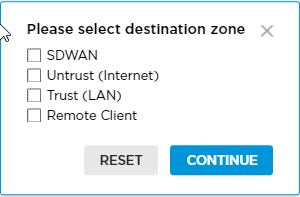
- SD-WAN—Select for the traffic coming to the gateway over overlay tunnels from remote SD-WAN branches.
- Untrust (Internet)—Select for internet facing WAN interfaces.
- Trust (LAN)—Select for LAN interfaces that are controlled by enterprises.
- Remote Client—Select the ingress zone for traffic coming from VSA clients.
- Click Add.
Configure Steering
When you configure steering, all traffic is load-balanced across all available WAN links, and voice and video traffic are prioritized dynamically to deliver the best user performance. You can specify SD-WAN steering and internet steering based on protocol, IP address, hostname, or application.
Note: You can configure internet steering only on spoke sites. When you view the Steering menu on non-spoke sites, the internet steering option does not display.
SD-WAN Steering
You can configure SD-WAN steering on spoke and non-spoke devices.
To configure SD-WAN steering:
- Click Configure in the left menu bar to open the Configure dashboard.
- Hover over the device in the honeycomb and click Configure to open the site information window.
- Click Next to open the Configuration > Network screen.
- Click the Steering tab to open the Configuration > Steering screen. Note that you can click Easy Steering Picks to populate steering with default values, see Default Configuration Values.

- Click SD-WAN Steering.
- Click one of the following boxes to open the configuration screen for the selection:
• Real Time
• Business Critical
• Default
• Low Priority
Create a Steering Rule
The actions available on the Real Time screen are identical to the Internet Steering, Business Critical, Default, and Low Priority screens. The examples below use the Real Time screen.
To create a new rule:
- From the Steering > SDWAN Steering screen, click Real Time to display the Real Time screen.

- Click + Rule to display the STEERING > SDWAN Steering > Real Time > Rules > Add screen.
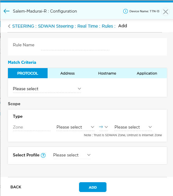
- Enter information for the following fields.
Field Description Rule Name Enter a name for the rule. Match Criteria Click Protocol, Address, Hostname, or Application to add details for that criteria type. Match criteria details are listed below in the Match Criteria for Rules section. Scope Source Zone Click the down arrow in the Please Select field. A pop-up window displays the configured interfaces and tunnels.
Choose a type: Untrust, Wired LAN, Wireless LAN, VPN, or an IPsec tunnel. To create a tunnel, see IPsec VPN.

Arrow Choose a
 one-way or
  two-way connection.
Destination Zone Click the down arrow in the Please Select field. A pop-up window displays the configured interfaces and tunnels.
Choose a type: Untrust, Wired LAN, Wireless LAN, VPN, or an IPsec tunnel. To create a tunnel, see IPsec VPN.

Select Profile Use the drop-down menu to select a profile. To create a new profile, see Create a Steering Profile. - Click Add. The rule is saved to the screen but not the Titan cloud.
- Click Save to save the rule to the Titan cloud.
Create a Steering Rule for SASE Gateway
Ensure that you create a profile before creating a rule. To create a new profile, see Create a Steering Profile for SASE Gateway.
To add a new steering rule for SASE gateway:
- Click Steering > SD-WAN Steering > Real Time to display the Real Time screen.

- Click the
 icon to add a new steering rule.

- Configure settings on the screen:

| Field | Description |
|---|---|
| Rule Name | Enter a name for the rule. |
| Match Criteria | There are 4 types of match criteria. Click Protocol, Address, Hostname, or Application to add details for a criteria type. See Match Criteria for Rules for match criteria details. |
|
Click the down arrow in the Please select drop-down list to select the protocol.
|
|
| Scope | |
| Source Zone |
Click the down arrow in the Please Select drop-down list. A pop-up window displays the zones that classify the traffic flows coming to the gateway from various sources. Select a source zone, and then click Continue.
|
| Arrow |
Choose a |
| Destination Zone |
Click the down arrow in the Please Select drop-down list. A pop-up window displays the zones that classify the traffic flows coming to the gateway from various sources. Select a destination zone, and then click Continue.
|
| Select Profile |
Use the drop-down list o select a profile. To create a new profile, see Create a Steering Profile. |
-
- Click Save to save the rule to the Titan cloud.
Match Criteria for Rules
You can use up to 4 types of match criteria in a rule: Protocol, Address, Hostname, or Application.
To specify match criteria:
- Protocol
- Click the Protocol tab to display the Protocol window.

- Click the FTP drop-down menu, then select a protocol. Titan Portal automatically populates the next field with common port numbers.
- If needed, click the port number field and edit the port number range.
- Click the Protocol tab to display the Protocol window.
- Address
- Click the Address tab to display the Address window.
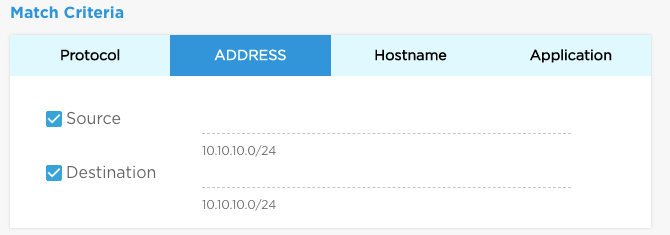
- If needed, click Source and enter a source IP address in CIDR format.
- If needed, click Destination and enter a destination IP address.
- Click the Address tab to display the Address window.
- Hostname
- Click the Hostname tab to display the Hostname window.

- If needed, click Source and enter a source hostname.
- If needed, click Destination and enter a destination hostname.
- Click the Hostname tab to display the Hostname window.
- Application
- Click the Application tab to display the Application window.

- Click Add or Modify Applications. Check boxes to add applications to the match criteria.
- Click Add. This saves the changes to the window but not the Titan cloud.

- Click the Application tab to display the Application window.
Edit or Delete Rule
To edit or delete a rule:
- From the Steering > SDWAN Steering screen, click Real Time, Business Critical, Default, or Low Priority.
- Click a rule name to edit a rule. Click the X to delete a rule.
- Click Save to save the changes to the Titan cloud.
Create a Steering Profile
The actions available on the Real Time screen are identical to the Business Critical, Default, and Low Priority screens. The examples below show the Real Time screen.
To create a new profile:
- From the Steering > SDWAN Steering screen, click Real Time to display the Real Time screen.

- Click +Profile to display the STEERING > SDWAN Steering > Real Time > Profiles > Add screen.

- Enter information for the following fields.
Field Description Profile Name Enter name you are assigning to the profile. Select Circuit Select WAN interface. Next Hop Select the next hop:

- Optimization—Enables all application traffic to select the best path.
- Enable—Set to enable if the profile is mapped to SD-WAN policy with at least one application in the match criteria.
- Disable—Set to disable if the SD-WAN policy does not have any applications in the match criteria.
- Select Gateway—Select one or more next hops from Versa-hosted SASE gateways.
- Select Devices List—Select one or more next hops from SD-WAN sites in the network.
- Select Circuits—Select one or more WAN links on the device.
Circuit Selection Criteria Click the circuit selection criteria, then specify:
- Latency—Click Low, or click Ms to specify the amount of latency in milliseconds.
- Packet Loss—Click Low, or click Percentage to specify the amount of packet loss by percentage.
- Delay Variation—Click Low, or click Percentage to specify the amount of packet loss by percentage.
Loss Recovery Choose the loss recovery method:
- Forward Error Correction (FEC)
- Packet Replication
Load Balance Choose the load balancing mechanism:
- Per Flow
- Per Packet
- Optimization—Enables all application traffic to select the best path.
- Click Add. The profile is saved to the screen but not the Titan cloud.
- Click Save to save the profile to the Titan cloud.
Create a Steering Profile for SASE Gateway
To create a new profile for SASE gateway:
- From the Steering > SDWAN Steering screen, click Real Time to display the Real Time screen.

- Click +Profile to display the Steering > SDWAN Steering > Real Time > Profiles > Add screen.

- Enter information for the following fields.
Field Description Profile Name Enter a name for the profile. Select Circuit Select WAN interface is not supported for SASE gateway. Circuit Selection Criteria Click the circuit selection criteria, then specify:
- Latency—Click Low, or click ms to specify the latency in milliseconds.
- Packet Loss—Click Low, or click Percentage to specify the percentage of packet loss.
- Delay Variation—Click Low, or click Percentage to specify the percentage of delay variation.
Loss Recovery Choose the loss recovery method:
- Forward Error Correction (FEC)
- Packet Replication
Load Balance Choose the load balancing mechanism:
- Per Flow
- Per Packet
- Click Add. The profile is saved to the screen but not to the Titan cloud.
- Click Save to save the profile to the Titan cloud.
Internet Steering
Internet Steering is used in a hub-and-spoke topology to provide DIA (local breakout) rather than remote break out from the hub.
When you save the configuration, the system automatically:
- creates specific traffic steering rules
- identifies the next hop as the local internet-accessible WAN interface
- creates a matching security rule to allow the traffic and route preference changes to ensure redundancy
- creates the next-hop setting for local internet breakout defined rules
To configure internet steering:
- Click Configure in the left menu bar to open the Configure dashboard.
- Hover over the device in the honeycomb and click Configure to open the site information window.
- Click Next to open the Configuration > Network screen.
- Click the Steering tab to open the Configuration > Steering screen. Note that you can click Easy Steering Picks to populate steering with default values, see Default Configuration Values.

- Click Internet Steering.

- Follow the instructions in the Create A Steering Rule section. The procedure to create a rule is the same.
Configure Routing
From the Routing tab, you can configure static routing and the OSPF and EBGP routing protocols. You can customize route redistribution for each routing protocol.
Configure Static IP Route
To configure a static IP route to a destination:
- Click Configure in the left menu bar to open the Configure dashboard.
- Hover over the device in the honeycomb and click Configure to open the site information window.
- Click the Routing tab and then click the Static tab. Enter the following information.

Field Description Interface Select the interface on which to enable static routing. Redistribute Click Redistribute to advertise the static IP route to the SD-WAN. Destination (IPv4/Mask) Enter the destination IP address and subnet mask. Next Hop Address (IPv4) Click Address or IPsec next to Next-Hop Address, and then enter one of the following. You must add IPsec from the WAN network to configure IPsec in routing.
- Next Hop (IPv4)—Enter the next-hop IP address. The IP address is automatically generated if this is not specified.
- IPsec—Select an IPsec tunnel. To create an IPsec tunnel, see IPsec VPN.
- Click the
 icon.
icon. - Click Save and then Publish.
Whenever the WAN IP address of the IPsec tunnel address pool changes, the previous IP address is not deleted as a static route in the SASE device and Versa Director. To delete the static route entry:
- Configure the static IP route with the IP address that needs to be deleted. See Configure Static IP Route.
- Click the
 icon, and then click Publish.
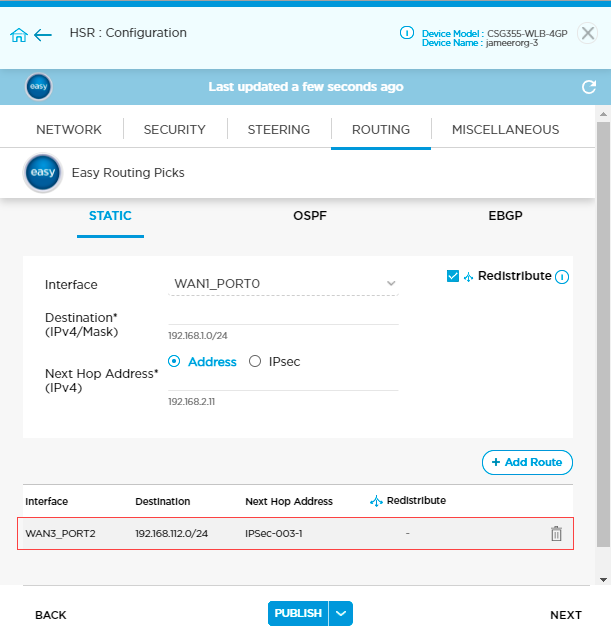
Configure OSPF
The Open Shortest Path First (OSPF) is an interior gateway routing protocol (IGP) that uses a link-state routing algorithm. OSPFv2 for IPv4 is defined in RFC 2328. You can configure OSPF instances on both LAN and WAN interfaces. On a WAN interface, OSPF applies only to the static WAN.
To configure OSPF:
- Click Configure in the left menu bar to open the Configure dashboard.
- Hover over the device in the honeycomb and click Configure to open the site information window.
- Click the Routing tab and then click the OSPF tab. Enter the following information.
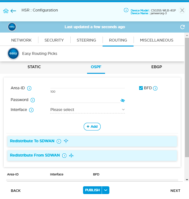
Field Description Area ID Enter the OSPF area ID. A backbone area has an area ID of 0.0.0.0. Areas with non-zero IDs are non-backbone areas.
BFD Click to enable BFD for OSPF. When BFD is enabled, if OSPF goes down, the router is marked as being down. Password Enter the password to authenticate the OSPF peers. MD5 authentication is used with a default key ID of 0. Interface Select the interface on which to enable OSPF. - Click the
 icon.
icon. - Click Redistribute to SD-WAN to configure the policy to control advertisement of OSPF routes received by the enterprise VPN network.

- If necessary, click Reorder Rules to enter rule reorder mode.
- To change a rule order, click the colored circle and drag the rule to a different spot in the rule set. The rule numbers are updated automatically.
- Click Save Reordered Rules to save the changes to the Titan cloud.
- Click the
 icon to add a new OSPF redistribution rule. Enter the following information.

Field Description Rule Name Enter a name for the rule. Match Criteria Enter the IPv4 address prefix to match. Action Select the action to take on matching routes:
- Allow—Click to allow routes on this prefix list.
- Deny—Click to deny routes on this prefix list.
- Click the
 icon, and then click Save.
 - Click Redistribute From SD-WAN to configure the policy to control advertisement of enterprise VPN routes received by the OSPF network.

- Click Reorder Rules to enter rule reorder mode.
- To change a rule order, click the colored circle and drag the rule to a different spot in the rule set. The rule numbers are updated automatically.
- Click Save Reordered Rules to save the changes to the Titan cloud.
- Click the
icon to add a new OSPF redistribution rule. Enter the following information.

Field Description Rule Name Enter a name for the rule. Match Criteria Enter the IPv4 address prefix to match. Action Select the action to take on the routes:
- Allow—Click to allow routes on this prefix list.
- Deny—Click to deny routes on this prefix list.
- Click the
icon, and then click Save.
Configure EBGP
The Border Gateway Protocol (BGP) is an exterior gateway protocol (EGP) used for exchanging routing information between gateway hosts in a network. BGP is the protocol commonly used between gateway hosts on the Internet.
To configure EBGP:
- Click Configure in the left menu bar to open the Configure dashboard.
- Hover over the device in the honeycomb and click Configure to open the site information window.
- Click the Routing tab and then click the EBGP tab. Enter the following information.

Field Description Interface Select the interface to which to connect to the BGP neighbor (peer). BFD Click to enable BFD, to provide fast forwarding-path failure detection and decrease reconvergence time. Neighbor Enter the IP address of the BGP peer. Password Enter the password to authenticate the BGP instance. Local AS Enter the local AS number.
Range: 0 through 4294967295 or <0..65535>.<0..65535>
AS Override Click to replace neighbor AS numbers with the local AS numbers from the AS path. Remote AS Enter the remote peer's AS number.
Range: 0 through 4294967295 or <0..65535>.<0..65535>
- Click the
 icon.
icon. - Click Outbound Policy to configure a routing policy that controls and filters prefixes that are advertised to the BGP peer.

- If necessary, click Reorder Rules to enter rule reorder mode.
- To change a rule order, click the colored circle and drag the rule to a different spot in the rule set. The rule numbers are updated automatically.
- Click Save Reordered Rules to save the changes to the Titan cloud.
- Click the
 icon to add a new outbound routing policy. Enter the following information.

Field Description Rule Name Enter a name for the rule. Match Criteria Select one or more match criteria:
- Click the Prefix tab and enter the IP prefix to match.
- Click the Community tab and enter the BGP community string to match. Enter the community string in as two 4-byte numbers (x:y) or as an 8-byte number.
Action Select the action to apply to matched prefixes. - Allow
Click to allow the prefixes that match the match criteria.
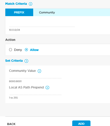
If you add a BGP peer for a WAN interfaces, you can add the following additional criteria:
- Community Value—Append the value of a single community specified by the set community to the list of communities if this policy matches the route.
- Local AS Path Prepend—Enter the number of times to prepend the local AS number to the AS path.
Range: 1 through 255
If you add a BGP peer for a LAN interface, you can add the following additional criteria:
- Community—Append the value of a single community specified by the set community to the list of communities if this policy matches the route.
- Deny
Click to deny the prefixes that match the match criteria. - Click the
 icon.
icon. - Click Inbound Policy to configure a routing policy that controls and filters prefixes that are received from the BGP peer.

- If necessary, click Reorder Rules to enter rule reorder mode.
- To change a rule order, click the colored circle and drag the rule to a different spot in the rule set. The rule numbers are updated automatically.
- Click Save Reordered Rules to save the changes to the Titan cloud.
- Click the
 icon to add a new inbound routing policy. Enter the following information.
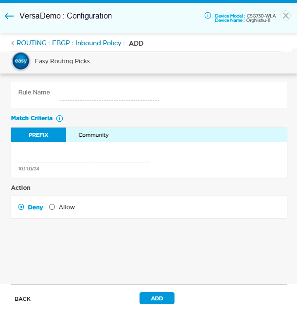
Field Description Rule Name Enter a name for the rule. Match Criteria Select one or more match criteria:
- Click the Prefix tab and enter the IP prefix to match.
- Click the Community tab and enter the BGP community string to match. Enter the community string in as two 4-byte numbers (x:y) or as an 8-byte number.
Action Select the action to apply to matched prefixes. - Allow
Click to allow the prefixes that match the match criteria.

If you add BGP peer for a WAN interface, you can add the following additional criteria:
- Community Value—Append the value of a single community specified by the set community to the list of communities if this policy matches the route.
- Local AS Path Prepend—Enter the number of times to prepend the local AS number to the AS path.
Range: 1 to 255
If you add a BGP peer for a LAN interface, you can add the following additional criteria:
- Community—Append the value of a single community specified by the set community to the list of communities if this policy matches the route.
- Deny
Click to deny the prefixes that match the match criteria. - Click the
 icon, and then click Save.
Configure ALG, SNMP, NTP, and Syslog (Miscellaneous Tab)
You can configure an application-level gateway (ALG) profile, SNMP, override DF bit, NTP server, and syslog server in the Miscellaneous tab for a branch.
ALG is a communication protocol that connects Versa Operating SystemTM (VOSTM) devices with various services. For example, if you want to send files through FTP and to establish calls with Versa devices using SIP, you configure ALG for a branch.
To enable the configuration of SNMP, you must configure an SNMP profile. For more information, see Add an SNMP Profile. You can configure only one LAN source interface.
To configure SNMP, you must first lock the device using the enable lock mode option in the honeycomb view in the Titan Portal home screen. The lock icon displays only if the device is deployed. A blue lock icon indicates that the device is unlocked, and a red lock icon indicates that the device is locked. After you publish the changes to Titan Portal, you must unlock the device.
To configure an ALG profile:
- Click Configure in the left menu bar to open the Configure dashboard.
- Hover over the device in the honeycomb, and click Configure to open the site information window.
- Click the Miscellaneous tab and enter the following information.

Field Description ALG Profile Select the ALG profile:
- FTP
- IKE-ESP
- PPTP
- SIP
- TFTP
Configure SNMP - Source Interface
Select the source interface to use to reach the SNMP server. - Source IP
Enter the IP address of the SNMP agent. Override DF Bit Select the override DF bit with IPsec tunnels to set the DF bit when encapsulating tunnel-mode IPsec traffic on a global or per-interface level. If the DF bit is set to clear, routers can fragment packets regardless of the original DF bit setting. Configure NTP Server - Set Time Zone
Select the timezone to set on the CPE device. - Set NTP Server (IP or Hostname)
Enter the IP address or hostname of the NTP server. - Set Source Network
Select the source network to use to reach the NTP server. Syslog Server IP Enter the IP address of the syslog server.
- Click Publish.
Configure Secure Access Service
The Versa Secure Access (VSA) service allows you to install Versa secure access client on your machine. VSA provides SD-WAN or secure VPN tunnel connectivity to enterprise networks and access to the internet through secure web gateway (SWG) services. The authentication database is selected based on the following setups:
- Microsoft Active Directory (AD)
- VOS local database
During the initial configuration, a reseller or MSP provisions the license in the Versa MSP portal using Versa Cloud Gateway and provides details in VSA services. Depending on whether you selected active directory or local database authentication, the VSA configuration is done from the Versa Titan Portal.
Configure a Secure Access Client
To configure a secure access client:
- Click Configure in the left menu bar to open the Configure dashboard.
- Hover over the device in the honeycomb and click Configure to open the site information window.
- Click Secure Access tab to open the Secure Access settings screen.
- Click Secure Access Client and enter the following information.

Field Description Secure Access App Profile - Secure Access Tunnel Selection
Select the split tunnel from the drop-down list:
- Full Tunnel—Select full tunnel for the secure access server, which allows all traffic including the Internet through SD-WAN.
- Split Tunnel—Select split tunnel for the secure access server, which allows a branch to use multiple internet links for VPN traffic flow.
Secure Access Profile - IPsec Tunnel Address Pool
Enter the following information for WAN1 and WAN2:
- Start Address—Enter the pool of IP addresses assigned to VSA client.
- End Address—Automatically assigned based on the start address.
- Netmask—Automatically assigned based on the start address.
- Client Control
- Two Factor
Click to enable two-factor authentication. Two-factor authentication is supported only for VSA local users. It is not supported for Active Directory (AD) users. - Always On
Click to enable VPN connection to be always on for the secure access client. - Edit Gateway
Click to allow Versa secure access client users to enable or disable a gateway. - Private Prefix Access
Enter an IP prefix accessible by clients and click the  icon. If this value is not specified, IP subnet is automatically allocated.
- Domain (FQDN) and DNS Resolver
Select domain (FQDN) and DNS resolver IP address:
- All Domains
- Specific Domains
- All Domains
- Name Server—Enter the DNS name server and click the
 icon. Name server is for all other domains that are not explicitly defined.
- Specific Domains
Enter the following information for private domains and click the
 icon.
icon.

- Domain Name—Enter the domain name in which the DNS resolver is located.
- Name Server Address—Enter the IP addresses of the DNS name servers. You can configure up to two DNS server IP addresses.
- Name Server—Enter the DNS name server.
Before you publish the secure access client configuration, you must create at least one static route. See Configure Routing for more information. - Click Save and then Publish from the drop-down list.
Configure Enterprise AAA
Versa Titan supports enterprise AAA using Microsoft Active Directory (AD). Active Directory can be part of the SD-WAN network, or you can configure IPsec backhaul with static IP addresses to your organization.
To configure enterprise AAA:
- Click Configure in the left menu bar to open the Configure dashboard.
- Hover over the device in the honeycomb and click Configure to open the site information window.
- Click Secure Access tab to open the Secure Access settings screen.
- Click Enterprise AAA and enter the following information.

Field Description MS Active Directory IP Address Enter the IP address of the LDAP server. FQDN Enter the fully qualified domain name for the LDAP server. SSL Mode Enabled Select SSL mode enabled:
- Click Yes to use SSL for the LDAP session.
- Click No to not use SSL for the LDAP session.
SSL Mode Select SSL mode for the LDAP session:
- LDAP—Use LDAP
- LDAPS—Use secure LDAP (LDAP over SSL)
CA Chain Select the Certificate Authority (CA) to use for the secure LDAP connection:
Default—Click default to use the default CA chain certificate.
Custom—Click custom to upload the .crt file and then click Browse file to upload your CA chain certificate.
Port Number Enter the port number. Bind-DN Name Enter the bind distinguished name (DN) authentication credentials for binding to the LDAP tree. Bind-DN Password Enter the bind password. Domain Name Enter the domain name in which the LDAP server resides. Base DN Enter the base DN of the LDAP directory location. NGFW initiates search for user and group information at the location. Bind Timeout Enter the bind timeout period, in seconds.
Default: 30 seconds
Search Timeout Enter the search timeout period, in seconds.
Default: 30 seconds
- Click Save and then Publish from the drop-down list.
Configure IPsec Backhaul
IPsec backhaul is used to create a tunnel from the SASE Gateway to a non-Versa device. To enable routing over this IPsec tunnel, you must also add a static IP route. See Configure Routing for more information.
To create an IPsec backhaul:
- Click Configure in the left menu bar to open the Configure dashboard.
- Hover over the device in the honeycomb and click Configure to open the site information window.
- Click the IPsec Backhaul tab and enter the following information.
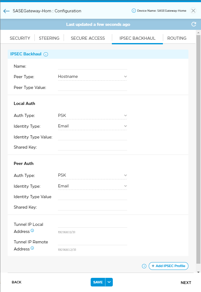
Field Description Name Enter the IPsec tunnel name. Titan Portal adds the tunnel name to the IPsec drop-down menu in the Static IP Route screen. Peer Type Enter the format for the peer type value: hostname, fully qualified domain name (FQDN), or IP address.
Peer Type Value Enter the peer value using the format selected in peer type. Local Auth Auth Type Displays the Auth type (PSK). Identity Type Enter the format for the identity type value: hostname, FQDN, or IP address.
Identity Type Value Enter the value in the format selected in identity type. Shared Key Enter the preshared key. Peer Auth Auth Type Displays the Auth type (PSK). Identity Type Enter the format for the identity type value: hostname, FQDN, or IP address.
Identity Type Value Enter the value in the format selected in identity type. Shared Key Enter the preshared key. Tunnel IP Local Address Enter the IP address of the local tunnel interface in CIDR format. Tunnel IP Remote Address Enter the IP address of peer. - Click the
 icon.
icon. - Click Save and then Publish from the drop-down list.
Deploy a Device Configuration
Once you have created a site, you can create and deploy its device configuration. Deploying copies the configuration information to the Versa Director. Before deployment, configuration information is saved to the Titan cloud portal only. Once the configuration is deployed, any changes you save are automatically copied to the Versa Director.
You can deploy a device configuration from any Configuration window by clicking Deploy at the bottom of the window. Once the configuration has been deployed, the Deploy option no longer displays.
To deploy a device configuration:
- From the bottom of any configuration window, click Deploy.

An Activation pop-up displays. You can choose from the following options.- WiFi—For appliances that support WiFi, use WiFi to activate from a laptop using Titan Portal or from a mobile phone running the Titan Mobile app.
- Versable—Activate the appliance using Versable from a mobile phone running the Titan Mobile app.
- GZTP—Activate the appliance over the internet using Titan Portal or Titan Mobile.
- Click an activation method.
- For GZTP activation only, enter appliance serial number if it is not already listed. Click the pencil icon then enter serial number appearing on the appliance.

- Click CONTINUE.
A confirmation message displays.
Undeploy a Device Configuration
Undeploying a device removes the configuration from the Versa Director. The saved device configuration is still present in the Titan cloud portal and you can still change settings and redeploy. You can undeploy a device configuration from the Inventory dashboard. See Inventory Actions.
Note the difference between undeploying and deactivating (removing) a device: Deactivating a device (removing a site) deletes its configuration information and returns the device license to inventory. Undeploying preserves the site and configuration information and the device license is still associated with the site.
Note: You must wait 5 minutes after undeploying a configuration before redeploying and activating an appliance. Titan must sync internal data structures when you undeploy; if this process is not complete you will receive an error message when you attempt to activate the appliance.
Activate an Appliance
You can activate an appliance after you have deployed its configuration. During activation the appliance is authenticated, and its configuration is copied from the Versa Controller. This section covers GZTP and WiFi activation. For Versable activation, see the Titan Mobile documentation.
Titan uses the activation method you chose during deployment. After deployment, you can still switch between WiFi and Versable methods. See Change Activation Method. To switch between GZTP and one of the other 2 methods, you must undeploy and then redeploy the configuration. See Undeploy a Device Configuration.
Note: All CSG appliances must be running at least VOS Release 20.2.1 for Release 20.2.1-based regions. Upon activation, all CSG appliances are automatically upgraded to Release 20.2.1 if they are not at the minimum software revision level. Note that the upgrade process can take as long as 1 hour depending on connectivity, latency, and available WAN bandwidth. To avoid disruption or delay, it is recommended that you upgrade the software on CSG appliances before activating them. Contact your Versa Titan reseller or Versa Networks account team for details and assistance.
Change Activation Method
To change the activation method for a device:
- From the Configure dashboard, hover over the device to view its options card.
- Click the Activation method to display a drop-down menu, then select Wi-Fi or Versable.
To switch between GZTP and one of the other 2 methods, you must undeploy and redeploy the device configuration. See Undeploy a Device Configuration.
Activate an Appliance Using WiFi
To activate an appliance using WiFi:
- On the appliance, make sure that WAN port 0 is connected to the internet and the power is turned on.
- On the appliance, make sure that the SIM card is inserted in the device if you are planning to use LTE for Internet connectivity backup.
- On a laptop, connect to WiFi on the appliance using the SSID and password below.
- SSID—VERSA-ZTP-WiFi
- Password—VR00M123
- Click Configure in the left menu bar to open the Configure dashboard.
- Hover over the device to view its options card, then click Click to Activate.

The Activate Device window displays.
- Click Activate in the Activate Device window.

The Web-UI Device Management portal displays in a browser tab.
- Click Start Activation in the Web-IU Device Management screen.

- Wait while the system configures the device. Watch progress in the Web-UI Device Management portal.

On the Activate Device window in Titan Portal, a status bar displays activation in progress. Do not close the Activate Device window until the activation message is displayed.

The device reboots when activation is complete. You are redirected back to the Titan device Configure dashboard where you can verify device activation status. See Verify Device Status.
Activate an Appliance Using GZTP
To activate an appliance using GZTP:
- On the appliance, make sure that WAN port 0 is connected to the internet and the power is turned on.
- On the appliance, make sure that the SIM card is inserted in the device if you are planning to use LTE for Internet connectivity backup.
- Click Configure in the left menu bar to open the Configure dashboard.
- From the Configure dashboard, hover over the device to view its options card. Click Click to Activate to begin activation.

- Wait approximately 10 minutes for the activation to complete.

Once activated, the device displays a green circle indicating an activated administrative state.

Troubleshoot Appliance Activation
If the device does not successfully establish connection or if device activation is not successful, you are prompted to try again or contact Versa technical support.
To troubleshoot device activation in the pop-up window:
- Click Get Started and follow the prompts.

- Check that the optical network terminal (ONT) and device are connected to the Ethernet. Note that ff you are activating over internet backup (LTE), connectivity to the ONT is not required.
- Click Next.

- Check that the device is plugged in and powered on.

- Make sure that the router is able to receive a strong LTE signal.
- If activation is unsuccessful, click Try Again. After multiple attempts, click Contact Support.
Verify the Device Status
The state of the device displays on the customer dashboard. View the state of the device by hovering over the device in the honeycomb. You can deploy a maximum of two devices per site.

Device status is categorized by color:
| Status Color | Description |
|---|---|
| Green | Device is active and reachable. |
|
Grey |
Device is not active. |
| Orange | Device is not deployed. |
|
Red |
Device is down. |
|
Yellow |
Device is out of sync with the configuration on the Director node and Titan. |
To verify that the device is active and that its operational state is up:
- Click Configure in the left menu bar to open the Configure dashboard.
- Hover over a site in the honeycomb and verify that the Administrative State is Active.
- In the Actions column, verify that the Configure link is active. To view details about the configuration, click Configure. See Configure Device Networking.

- Click Monitor in the left menu bar to open the Monitor dashboard.
- Hover over a site in the honeycomb and verify that that the Operation State is Up and that the device and Versa Director status are in sync.

- In the Actions column, do the following:
- Click Monitoring Dashboard to view Networking, Security, and Device status in the Monitor window. See Monitor Device Status.
- Click Reboot Device to reboot the device.
- Click Restart Services to restart the Titan device services.
- Click Sync Configuration to sync the configuration changes from the device to Versa Director and Titan Dashboard.
Activate an Appliance with a PPPoE Interface
To activate an appliance with a PPPoE-enabled circuit on the WAN:
- The appliance must be running the latest version of VOS software, and it must match the VOS software version on the Versa Director.
- You must use the mobile app with the Versable or WiFi (URLZTP) activation method to activate the appliance. The GZTP activation method is not supported.
In many deployments, activation of an appliance over a PPPoE WAN circuit does not function for appliances shipped from the factory with an older version of the VOS software. To complete the activation and upgrade, you need another DHCP-enabled WAN circuit or LTE. You can achieve this in one of the following ways:
- The device has a PPPoE WAN circuit and an additional DHCP-enabled WAN or LTE circuit that does not use PPPoE. In this case, you use the additional DHCP-enabled WAN circuit to activate and upgrade the branch.The PPPoE WAN circuit can be used after the device activation and upgrade.
- The device has only a PPPoE WAN circuit. In this case, you must have an additional temporary WAN circuit that is not PPPoE-based to use for the device activation and upgrade. The temporary WAN circuit can be DHCP-enabled Ethernet or LTE. If the additional WAN link is not available for activation, contact Versa Networks Customer Support.
To configure an additional temporary WAN circuit on the device:
- Configure a DHCP-enabled Ethernet WANT1(Port0) circuit. See Configure WAN Connections.
- Deploy the device and connect the DHCP-enabled WAN1(Port0) to the device. See Deploy a Device Configuration.
- Start the activation and upgrade process. See Activate an Appliance.
- Monitor the status until the device is up. Ensure that an IP address is assigned on WAN1Port0. See Verify the Device Status.
After the device activation and upgrade complete, you can lock the device, remove the additional WAN link configuration, and configure WAN1 as the PPPoE WAN circuit. See Edit WAN or LTE Interfaces in an Active Device. Ensure that WAN1 receives an IP address, which may take up to 5 minutes.
The appliance is upgraded during the activation process, which may take 30 minutes or more depending on the bandwidth of the WAN link. Do not disconnect the device until the upgrade process is complete. You can monitor the device upgrade status from the Titan Monitor page.
Configure and Activate an HA Site
To configure an HA site in Titan Portal, set up the appliance wiring on 2 appliances and then configure the site. You must use identical license types on 2 identical appliances to create an HA pair. Each device must be deployed and activated separately.
Install HA Wiring
Install the wiring on the appliances:
- Wire the 2 appliances before you configure them for HA. When wiring the device for HA, the ports are divided into 3 sections. WAN ports are the lower numbered ports on the left. LAN ports are the higher numbered ports on the right. Assign a port in the middle, called a cross-connect port, this marks the boundary between the WAN and LAN ports.
- WAN ports must be connected starting with port 0, then port 1, and so on. WAN ports are always the lower port numbers. Attach port 0 on both devices to a WAN.
- Determine the cross-connect port number.
- If both devices use the same number of ports for WAN connections, assign the next port number after the highest WAN port number as the cross-connect port number. For example, if you use ports 0 and 1 as WAN ports on both devices, then use port 2 as the cross-connect port.
- If the devices use an unequal number of WAN connections, use the device with the larger number of WAN connections to determine the cross-connect port number. For example, if the first device uses ports 0 and 1 as WAN ports and the second device uses only port 0 as a WAN port, then use port 2 as the cross-connect port on both devices. Notice that port 1 on the second device is unused in this case.
- Connect the cross-connect port on the first device to the cross-connect port on the second device using a Cat6 Ethernet cable. Again, you must use the same port number on both devices for the cross-connect.
- The higher numbered ports are used as LAN ports. Connect the first LAN port (that is, the port immediately to the right of the cross-connect port) to the local LAN. This port is used for Virtual Router Redundancy Protocol (VRRP) communication.
The following diagram displays an example configuration assigning one WAN port, a cross-connect port, and one LAN/VRRP port on each device in an HA pair. In this case, both devices use the same number of ports for WAN connections and you should install a Cat6 Ethernet cable (not shown) to connect the 2 cross-connect ports.

Create an HA Site
To create, deploy, and activate an HA site:
Note: When deploying HA devices, you must click the HA box before deploying the site. If a device configuration is already deployed for a site and you drag-and-drop another license into the site within the honeycomb on the dashboard, this does not auto-configure HA. In that case you would need to undeploy and then redeploy using the instructions below to configure HA. See Undeploy a Device Configuration.
- Click Configure in the left menu bar to display the Configure dashboard.
- Click a license type in the bottom menu bar to display available licenses. You must have at least 2 licenses of the same type to configure HA.

- Drag and drop a license onto the dashboard. The New Site Configuration window displays automatically.

- Enter site configuration information.
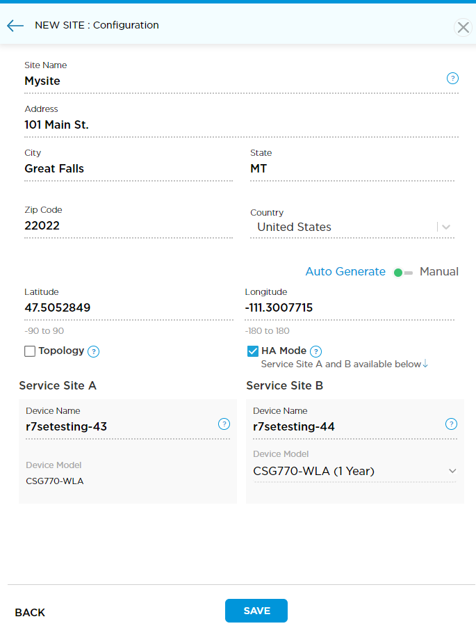
- Enter site name and location information.
- Click the HA Mode box.
- Click Save to save the configuration.
- The honeycomb displays the new site with two devices. Site A is on the left, and Site B is on the right. The device marked with pink is the primary device.
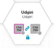
- Create and save configurations for each device separately. The first LAN, which is the next port after the cross-connect port, is a shared LAN and can be configured on the first device only. This configures the LAN on both devices. If one device fails, the other continues to operate the LAN. See Configure Device Networking, Configure Security, and Configure Steering for information on creating and saving a configuration.
- Deploy the device configurations:
- In the honeycomb for the new site, click the device on the left to display its options card, then click Configure to open a site configuration window.
- Click Deploy, then choose an activation method.
- Repeat these steps to deploy the configuration for the device on the right, choosing an identical activation method.
- Activate each device using the method selected in the previous step. See Activate an Appliance for WiFi and GZTP activation. See the Titan Mobile documentation for Versable activation. You must activate each device separately.
- After the device is activated, the administrative state for the site in the honeycomb should display as active.

Deploy a Branch in AWS
This section describes how to configure a branch in AWS to automate instantiation, configuration, and monitoring of a VOS branch in the AWS Virtual Private Cloud (VPC).
AWS Prerequisites for vCSG for Versa Titan
This section describes the prerequisites for deploying a vCSG in your AWS VPC(s) through the Versa Titan dashboard.
Before you begin, perform the following tasks on AWS.
- Create an AWS VPC, then mount to the internal gateway to reach the internet.
- An Amazon Machine Image (AMI) should be present, with VOS Release 20.2.x, based on the Versa Director being used. Provide the AWS account ID to Versa support so they can image into your account.
- Collect the LAN subnet information for the VPC. Note that you must configure the vCSG LAN interfaces to match the AWS environment networks prior to deployment of the virtual device.
IAM Policy for CMS Connector
When you perform authentication using a CMS connection, you must use the following IAM policy so that the CMS connector functions on AWS:
{
    "Version": "2012-10-17",
    "Statement": [
        {
            "Effect": "Allow",
            "Action": [
                "ec2:DescribeAddresses",
                "ec2:DescribeInstances",
                "ec2:MonitorInstances",
                "ec2:DescribeRegions",
                "ec2:DescribeVpcAttribute",
                "ec2:DescribeSecurityGroups",
                "ec2:DescribeImages",
                "ec2:DescribeNetworkInterfaces",
                "ec2:DescribeAvailabilityZones",
                "ec2:DescribeVpcs",
                "ec2:DescribeAccountAttributes",
                "ec2:AssociateAddress",
                "ec2:DisassociateAddress",
                "ec2:DescribeNetworkInterfacePermissions",
                "ec2:DescribeSubnets",
                "ec2:AllocateAddress",
                "ec2:ReleaseAddress",
                "ec2:DescribeKeyPairs"
            ],
            "Resource": "*"
        },
        {
            "Effect": "Allow",
            "Action": [
                "ec2:TerminateInstances",
                "ec2:CreateTags",
                "ec2:RunInstances",
                "ec2:DeleteNetworkInterface",
                "iam:ListInstanceProfiles",
                "ec2:ModifyNetworkInterfaceAttribute",
                "ec2:StopInstances",
                "ec2:ModifyInstanceAttribute",
                "ec2:ReplaceIamInstanceProfileAssociation",
                "ec2:CreateVolume",
                "ec2:CreateNetworkInterface",
                "ec2:DeleteVolume",
                "iam:PassRole",
                "ec2:StartInstances",
                "ec2:DisassociateIamInstanceProfile",
                "ec2:CreateSecurityGroup",
                "ec2:DeleteSecurityGroup",
                "ec2:AssociateIamInstanceProfile"
            ],
            "Resource": [
                "arn:aws:iam::*:instance-profile/*",
                "arn:aws:iam::*:role/*",
                "arn:aws:ec2:*:*:subnet/*",
                "arn:aws:ec2:*:*:instance/*",
                "arn:aws:ec2:*:*:volume/*",
                "arn:aws:ec2:*:*:security-group/*",
                "arn:aws:ec2:*:*:network-interface/*",
                "arn:aws:ec2:*:*:key-pair/*",
                "arn:aws:ec2:*::image/*"
            ]
        }
    ]}
Create an IAM Role
For information about IAM and how to create and allocate specific IAM privileges, refer to the following AWS guides:
- https://docs.aws.amazon.com/IAM/latest/UserGuide/resources.html#resources-iam-and-other-services
- https://docs.aws.amazon.com/AWSEC2/latest/UserGuide/security-iam.html
- https://docs.aws.amazon.com/AWSEC2/latest/UserGuide/iam-roles-for-amazon-ec2.html
To create an IAM role:
- Login to your AWS account.

- Click AWS IAM Credentials tab, and then click the Create access key.

If you have created an access key earlier, you must keep the access key ID and secret access key values. This information is required when you create the CMS connector in the Versa Titan dashboard. - Create an AWS VPC. For more information, see https://docs.aws.amazon.com/vpc/latest/userguide/vpc-getting-started.html.

You can create a VPC or use an existing VPC that has the CIDR and any subnets associated to it. If you create a new VPC, assign a CIDR block or blocks to the VPC. For Versa Titan vCSG, it is not required to create specific subnets from your CIDR blocks to instantiate an EC2 instance. This process is automated from Versa Titan using CloudFormation templates. For more information on AWS VPCs, see the following: - Select Your VPCs in the left navigation pane to view information about your VPC.

The LAN and WAN interfaces of your vCSG must be allocated or assigned an IP address that is within your CIDR block. - Select Route Tables in the left navigation pane. Then click Routes tab to display the route information.

- Select Internet Gateways in the left navigation pane. Then click Create Internet gateway and enter the following information.
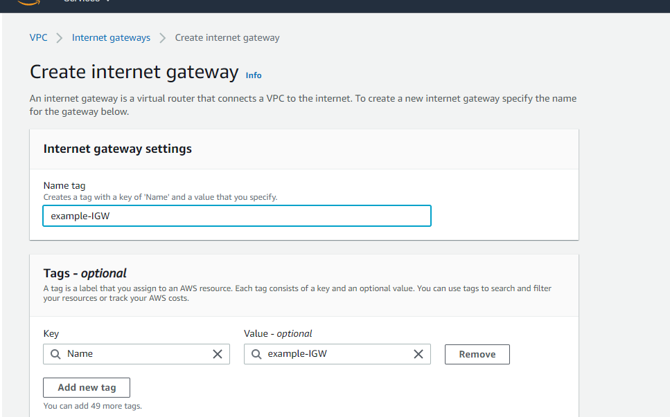
Field Description Name tag Creates a tag with a key of name and a value that you specify. Tags - optional Enter a tag value for the following:
- Key
- Value - optional
- To associate an internet gateway to VPC, select Attach to VPC from the Actions drop-down list.

- In the Available VPCs field, enter the VPC name. The VPC will display only if it is not attached to an internet gateway.
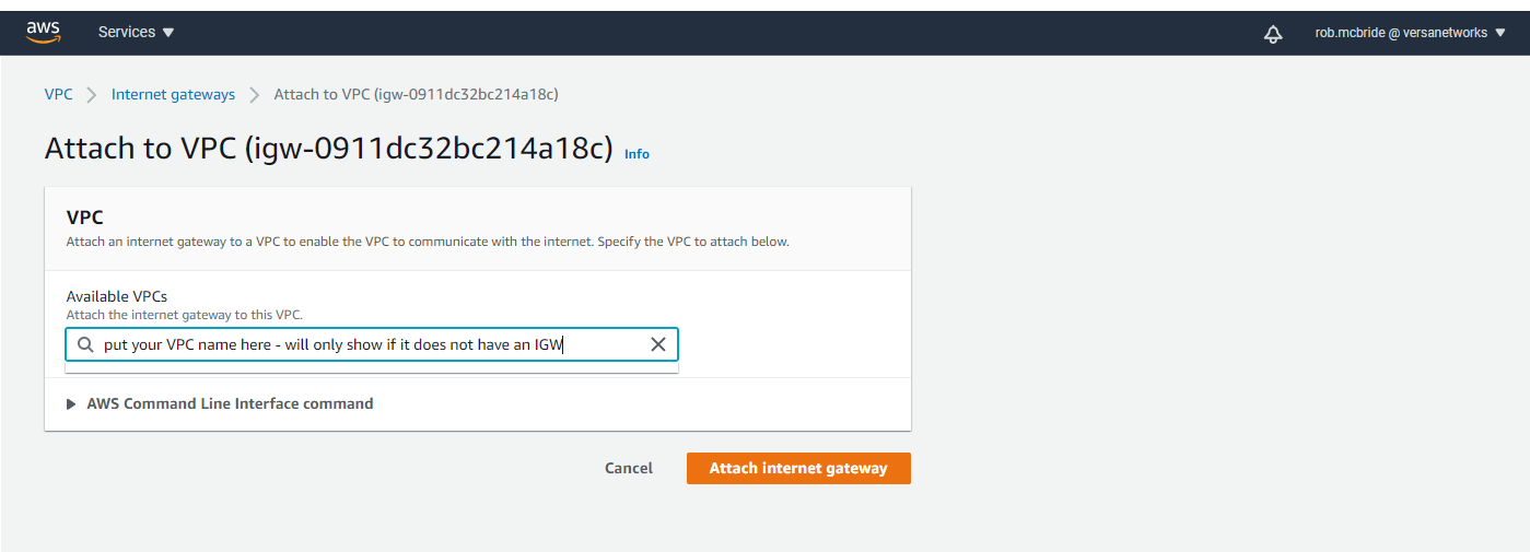
- Click Attach Internet gateway.
- To add a default route to internet gateway, select Route Tables in the left navigation pane. Then click Edit Routes.

- In the Edit Routes page, click Add route and enter the route information.
- Click Save Routes.
- Send the AWS account information to Versa Support Team to get your VOS Amazon Machine Image (AMI).
- Copy the AMI to the relevant region.

Configure a Branch in AWS
This section describes how to configure a branch in AWS to automate instantiation, configuration, and monitoring of a VOS branch in the AWS Virtual Private Cloud (VPC).
To configure a branch in AWS:
- In Titan Portal, click the Inventory icon in the left menu bar to display the Inventory dashboard. Then click +Cloud Account to display the Add Cloud Account window.

- Create a Cloud Management System (CMS) connector.
- Enter a name for the CMS.
- Enter the access key ID and secret key for the AWS account.
- Click Add.

- Wait 3 minutes until the CMS account displays. A license is now available from the Configure dashboard.

- Click Configure to display the Configure dashboard, then click the vCSG icon on the bottom of the dashboard to display available licenses. Select the license you just created and drag and drop onto the dashboard to create a new honeycomb. The New Site: Configuration window displays automatically.

- In the New Site: Configuration window, enter the following information.
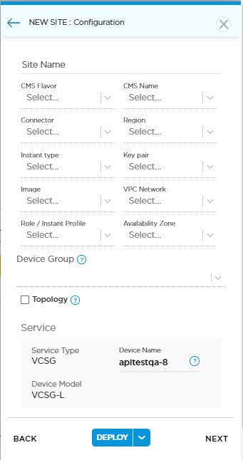
Field Description Site Name Enter a name for your site. CMS Flavor Select AWS in the CMS Flavor drop-down list. CMS Name Select the CMS name in the drop-down list. This is the cloud account that is configured in the inventory section. Connector Select the CMS connector. Region Select the region, that is the VPC you deploy the vCSG. This must be the same VPC and region that is created earlier. Instant type Select the instance type for vCSG. The qualified instance types are:
- vCSG-Medium—4 vCPU
- vCSG-Large—8 vCPE
- vCSG-XL—16 vCPU
Key pair Select the AWS key pair. Image Select the AMI that you received from Versa. VPC Network Select the VPC network where the vCSG EC2 instance is created. Role/Instant Profile Select the IAM role. Availability Zone Select the availability zone. Device Group Enter a device group name. By default, Versa Titan uses the syntax ORG-NAME-LICENSE-# as the device name. Topology Click to enable topology. The default topology is Full Mesh (Any-to-Any) site communication. Alternatively, the device can be configured in one of the following options: - Hub—Configure the device as a hub in a hub-spoke topology
- Hub controller—Configure the device as a hub controller in a hub-spoke topology.This device takes up a dual role of a hub and a controller.This function is typically required when branches are connected to a private MPLS network that has no direct access to the Versa hosted controller on the public internet.
- Spoke—Configure the device as a hub in a hub-spoke topology.
- Click Next.

- Click the LAN icon. You must configure the vCSG LAN interfaces to match the AWS environment networks.
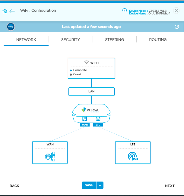
- Click the Ethernet Ports icon.

- Enter the DHCP subnet and range information and then click Save. This returns you to the New Site: Configuration screen.

- Click the down arrow, then click Deploy. Wait 5 minutes then refresh the screen.

Deploying an AWS configuration automatically activates the site.
- The Administrative state color circle turns green indicating that the site is now active. Hover over the device icon to display device information, name, and actions.

Verify AWS Branch Deployment
To verify and confirm the deployment and activation of AWS branch:
- Browse to AWS console.
- Click CloudFormation > Stacks.

- Click CloudFormation stack name.
- Click Events tab and then click refresh button to check the status.
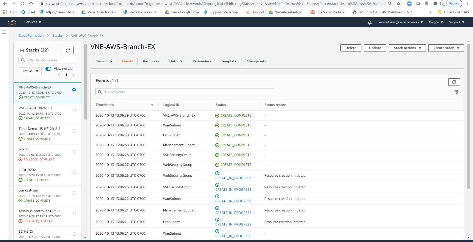
If you see an error, failure, or rollback, check the CloudFormation logs and contact Versa Titan Support. - Click Resources tab to view various subnets that CloudFormation stack creates.

- Click the Template tab to view the template parameters.

- Navigate to AWS Console > Instances to verify that the EC2 instance is created.

- Click the EC2 instance named after the device name of your vCSG site for EC2 instance information.

Deploy SASE Gateway Services
SASE gateways are multitenant gateways hosted and maintained by Versa Networks at various data centers in the U.S., Japan, and Europe. SASE gateways provide security firewalls and QoS-enabled traffic steering for branch networks and secure access clients. Customer branch devices are automatically connected to all the gateways in the SD-WAN as a full mesh. You can create steering and firewall rules for SD-WAN, internet, and secure web gateway zones.
When you are enrolled for the SASE gateway service, the corresponding tenant is instantiated on the SASE gateway and an instance of the SASE gateway becomes available in the Versa Titan customer dashboard. To configure security and SD-WAN steering policies options in a Titan branch, see Configure Security and Configure Steering.
Create an MSP Account
An operator or store administrator can create an MSP account and assign user roles and privileges. You cannot assign more privileges than the account you are using. An MSP can log in to Titan Portal and can add other MSPs and resellers.
To create an MSP account, first, you log in as an operator and create a store administrator. Then, you log in as a store administrator and create an MSP.
After you create a store administrator or MSP, a confirmation email is automatically sent to the email address that directs customers to the login screen and allows them to set their password. This email address automatically becomes the login name for the account.
To create a store administrator account:
- Log in to Titan Portal as an Operator, and create a new Store Administrator.
- Enter your username and password, and click Login.
- Click Users in the left menu bar to open the Users dashboard. Then click + Add User.

- Enter the following information.

Field Description First Name Enter the user's first name. Last Name Enter the user's last name. Email Address Enter an email address for the user. This automatically becomes the login name for the account. You can change the email address after creating the account but not the login name. Phone Number Select the country code and enter the phone number for the user. Titan Mobile pushes notifications to this phone number. Two Factor Authentication Slide the toggle to enable or disable two-factor authentication. Roles Select Store Admin.
Create as New Store Click to enter information for the new store. Store Enter new store name. Provider Name Enter VERSA. Deploy Click to create a new region on the Director node for the new store. Regions Click to select regions. You can select multiple regions attached to the Titan node. Allowed Product Select the products that the MSP can order:
- Cloud Appliances
- Versa Appliances
- Versa Cloud Gateway
- Versa Virtual Appliances
- White Box
Privileges Select the privileges:
- Manage Customer—Click to access the customer's organization.
- Manage Service—Click to access the dashboard and read and write customer networks or devices onboarded by this specific store admin.
- Click Create.
To create an MSP account:
- Log in to Titan Portal as a store administrator and create a new MSP.
- Enter your username and password, and click Login.
- Click Users menu in the left menu bar, click + Add User, and then enter the following information.

Field Description First Name Enter a first name for the MSP. Last Name Enter a last name for the MSP. Email Address Enter an email address for the MSP. This automatically becomes the login name for the account. You can change the email address after creating the account but not the login name. Phone Number Select the country code and enter the phone number for the MSP. Titan Mobile pushes notifications to this phone number. Two Factor Authentication Slide the toggle to enable or disable two-factor authentication. Roles Select Managed Service Provider (MSP).
Create as New MSP Click to enter information for the new MSP. MSP Enter a name for the MSP. Deploy Click to create a new region on the Director node for the MSP. Regions Click to select regions. If you are creating the MSP under the store admin that you have already created, the region that you selected while creating the store admin is automatically selected. Allowed Product Select the products that the MSP can order:
- Cloud Appliances
- Versa Appliances
- Versa Cloud Gateway
- Versa Virtual Appliances
- White Box
Privileges Select the privileges:
- Manage Customer—Click to access the customer's organization.
- Manage Service—Click to access the dashboard and read and write customer networks or devices onboarded by this specific MSP.
- Click Create.
Add SASE Gateway Devices
SASE gateway is supported on the following Versa Networks hardware appliances:
- CSG700 series appliances
- CSG770 model
- CSG1000 series appliances
- CSG1300 model
- CSG1500 model
- cCSG appliances
- cCSG-L model
- cCSG-XL model
- vCSG appliances
- vCSG-L model
- vCSG-XL model
To add a SASE gateway device:
- Log in to Titan Portal as an MSP.
- Enter your username and password, and click Login.
- In the Organizations dashboard, locate the organization in the grid, click the 3-dot icon, and then click Add Devices.

- In the Add Device Details popup window, select the hardware device. Customers can purchase a private SASE gateway from cloud gateway through a store admin, MSP, or reseller. For more information, see Add the SASE Gateway Service.
- CSG
- cCSG
- vCSG
- To add a CSG device, click CSG as the hardware device, and then enter the following information.

Field Description Device Type Select the hardware device type CSG700 or CSG1000.
Region Choose a region:
- Americas & EMEA
- Asia
Hardware Model Select the hardware model:
- For CSG700 series, select any CSG770 model.
- For CSG1000 series, select any models.
Wireless Interface Click to display the wireless interface menu, and then select wireless interface. Add-on NIC Click to display the add-on NIC menu, and then select the add-on. Private Gateway Click to enable Versa Secure Web Gateway (SWG) service and the Versa Secure Access (VSA) service. Subscription Duration Select the length of the subscription:
- 1 year
- 3 years
- 5 years
PO License Start Date Enter the purchase order license start date PO Number Enter the purchase order number Hardware Replacement Select the hardware replacement time:
- Next business day
- Same business day
Quantity Enter the number of hardware devices to order. - To add cCSG or vCSG device, click cCSG or vCSG button, and then enter the following information.

Field Description Device SKU Select the SKU for the device:
- For cCSG
- cCSG-L
- cCSG-XL
- For vCSG
- vCSG-L
- vCSG-XL
Private Gateway Click to enable Versa Secure Web Gateway (SWG) service and the Versa Secure Access (VSA) service. Subscription Duration Click the length of the subscription:
- 1 year
- 3 years
- 5 years
PO License Start Date Enter the purchase order license start date PO Number Enter the purchase order number Quantity Enter the number of hardware devices to order. SASE Gateway Options Versa Secure Web Gateway (SWG) Service (Group of Fields) Click to enable SWG service. - Service Tier
Select the service tier:
- Essential
- Professional
- Users
Enter the number of users. You must add minimum 50 users. Versa Secure Access (VSA) Service (Group of Fields) Click to enable VSA service. - Service Tier
Select the service tier:
- Essential
- Professional
- No of Client User
Enter the number of client users. You must add minimum 50 users. - For cCSG
- Click Submit.
Configure and Activate SASE Gateway Devices
This section provides step-by-step procedures for configuring and activating SASE gateway devices on supported Versa Networks hardware appliances.
To configure and activate SASE gateway devices:
- Create a site using a software license.
- Create a device configuration for the site. When you save the device configuration, it is stored in the Titan cloud portal. You should configure WAN interfaces before deployment.
- Deploy the device configuration to the Versa Controller node, to inform the Controller node that the configuration exists.
- Activate the appliance.
Create a Site for the SASE Gateway
To create a site for the CSG770 model, CSG1000 series, and vCSG series appliances:
- Log in to Titan Portal as an MSP.
- Enter your username and password, and click Login.
- In the Organizations dashboard, click the MSP provider organization in the grid.

- Click Configure in the left menu bar to display the Configure dashboard.
- Click one of the license package icons to display the available license packages. To add the site to the honeycomb, drag the license package onto the dashboard.
- CSG700 Series
- CSG1000 Series
- cCSG Series
- vCSG Series

- In the New Site: Configuration window, select a region and click Continue.

- Enter information for the following fields, and then click Next.
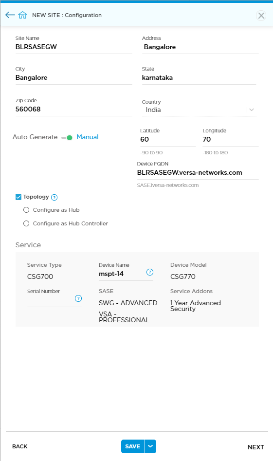
Field Description Site Name Enter a name for site. Address Enter the street address, zip code, city, state, and country. Latitude and Longitude - Auto Generate—Click the Auto Generate toggle to enable the determination of latitude and longitude coordinates automatically.
- Manual—Click the Manual toggle to enable the determination of latitude and longitude coordinates manually. This is the default.
Device FQDN Enter the FQDN for the device. When you create a certificate, the device FQDN name and the VSA certificate domain name must be the same. Topology Click to configure the site role:
- Configure as Hub—Configure the device as a hub in a hub-and-spoke topology
- Configure as Hub Controller—Configure the device as a hub controller in a hub-and-spoke topology. This device takes up a dual role of a hub and a Controller node. This function is typically required when branches are connected to a private MPLS network that has no direct access to the Versa Networks–hosted Controller node in the public internet.
- None—If you do not select a topology, only the SASE gateway is attached.
Service View device details.
- Serial Number—Enter the serial number of the appliance.
- Click the WAN box to display the Network > WAN screen.
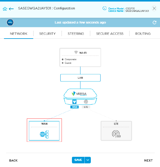
- Enter the static IP address for the WAN1 Port0 interface, and then click Save.

- Click the LAN box to open the Network > LAN > Ethernet Ports screen.

- Select LAN1 Port1 from the drop-down, and click the delete icon to delete the LAN port.

- Go to Network > WAN and click +WAN to configure Port1 as the WAN2 secondary port.

- Click Continue.

- Click Save, and then click the down arrow next to Save to display the Deploy popup window.
- Click Deploy. Note that you can deploy a SASE gateway like a normal device and you can activate it using the global GTP, WiFi, and Versable methods. To deploy and activate a device, see Deploy a Device Configuration and Activate an Appliance.
Install Certificates for VSA
A certificate authority (CA) is an entity that issues digital certificates that are used to verify the ownership of a public key. The digital certificates allow a party to trust the signature that is made by a private key that corresponds to the certified public key.
After a Titan device requests a certificate from a CA server, the CA server issues the certificate. You then need to upload the certificate to the CA database so that it can be used for verification.
Note: After a SASE gateway devices is activated, you need to log in as an MSP user and install all necessary certificates for VSA. MSP must create a tenant only after uploading the VSA certificate. When an MSP user creates a tenant, Titan copies the necessary VSA certificates to the tenant. You need to install the VSA certificate only if a SASE gateway is purchased for VSA service.
The following table describes information about SASE gateway certificate management.
| SASE Gateway Certificate Management | MSP Provider Organization | MSP Tenant Organization | Branch or Hub | Notes |
|---|---|---|---|---|
| VSA certificates | Titan copies necessary certificates to the provider organization. | Titan copies necessary certificates to the tenant organization. | NA | User must upload a VSA certificate after the SASE gateway device is activated. When the user creates other tenant organizations, the same certificate is copied to all tenants. |
| System-generated TLS decryption certificate | TLS decryption profile configured with default certificate. The certificate name and provider organization name are the same. | TLS decryption profile configured with default certificate. The certificate name and tenant organization name are the same. | TLS decryption profile configured with default certificate. The certificate name and tenant organization name are the same. | System generates TLS decryption certificate with the organization name using Versa root certificate. |
| User-generated TLS decryption certificate | User can upload their own certificate. | User cannot upload their own certificate. | User can upload their own certificate. | Only device owner can upload their own certificate. |
Before you upload a CA certificate, you must upload a key file with the extension .key.
To upload a key file:
- Locate the device in the grid, and then click the 3-dot icon in the Action column to display available actions.

- Click Upload CA Certificates and then click Upload Key.
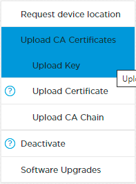
- In the Add Key popup window, enter the following information.

- Enter a key name and password.
- Click Browse file to select the key file to upload. The file must be in .key format.
- Click Add.
- Click Upload CA Certificates, and then click Upload Certificate.

- In the Add CA Certificate popup window, enter the following information.

- Enter a certificate name.
- Select the key file name.
- Click Browse file to select the CA certificate file to upload. The file must be in .crt, .cer, or .pem format.
- Click Add. The certificate file is displayed.
- Click the
 icon to download the file.
- Click Upload CA Certificates and then click Upload CA Chain.

- In the Add CA Chain popup window, enter the following information.

- Enter a CA chain name.
- Click Browse file to select the CA chain file to upload. The file must be in .crt format.
- Click Add.
Add the SASE Gateway Service
An MSP provider organization can select cloud gateway services and order the SWG and VSA services. You can select available SASE gateways and advanced services such as VLAN and port details. Note that you can select cloud gateway services as a SASE gateway to get the service. If you have already added a SASE gateway, but then you cannot select the cloud gateway option.
To add a SASE gateway service:
- In the Organizations dashboard, locate the organization in the grid, click the 3-dot icon, and then click Add Devices.

- In the Add Device Details popup window, click Cloud Gateway and enter information for the following fields.

Field Description SASE Gateway Region Select the SASE gateway regions.
- Click Advanced option to enter the VLAN and port details for the SASE gateway services. If you do not select any VLAN ID, the organization ID is taken as the VLAN ID by default.
- Advanced
Click the Advanced button to enter the VLAN and port details for the SASE gateway services. If you do not select any VLAN ID, the organization ID is used, by default, as the VLAN ID.

Versa Secure Web Gateway (SWG) Service (Group of Fields) Click to enable the SWG service. - Service Tier
Select the service tier:
- Essential—Only firewall and URL filtering are available.
- Professional—All security services are available, including firewall, URL filtering, antivirus, IPS, and TLS decryption.
- Users
Enter the number of authorized users. The minimum number of users is 50. Versa Secure Access (VSA) Service (Group of Fields) Click to enable the VSA service. - Service Tier
Select the service tier:
- Essential—Supports only split-tunnel traffic. For a split tunnel, the learned routes are redirected to the SASE gateway and the rest of the traffic is redirected through local internet.
- Professional—Supports full-tunnel traffic. For full-tunnel traffic, all the tunnel traffic is encrypted and redirected to the SASE gateway.
- No of Client User
Enter the number of authorized users. The minimum number of users is 50. - User Authentication
Select the user authentication method:
- Enterprise Active Directory—Authenticate using an LDAP server.
- Local User Directory—Authenticate using a username and password.
Subscription Duration Select the length of the subscription:
- 1 year
- 3 years
- Click Submit.
View SASE Gateway Licenses
To manage SASE gateway licenses and devices in the Titan Inventory:
- Click the Inventory icon in the left menu bar to open the Inventory dashboard.
- Select SASE Gateway from the device type drop-down list at the top of the screen.
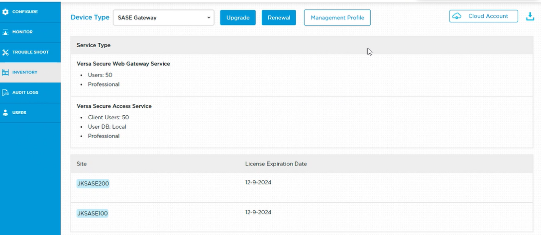
Upgrade or Renew SASE Gateway Licenses
You must upgrade a SASE gateway license before the license expires. If a license has expired, the Configure and Inventory dashboards display the site with license expired status and the network configuration window displays in purple and has read access only. You must renew the license to make any changes to the device configuration.


To upgrade or renew a SASE gateway license in the Titan Inventory:
- Click the Inventory icon in the left menu bar to open the Inventory dashboard.
- Select SASE Gateway in the Device Type field.
- Click Upgrade.

- In the Upgrade popup window, enter the following information.

- For upgrade:
- Additional Gateway Users for SWG service. The minimum number of gateway users is 50.
- Additional Client Users for VSA service. The minimum number of gateway users is 50.
- Enter additional number of days for the renewal of the license.
- For upgrade:
- Click Submit.
- In the Upgrade popup window, enter the following information.
- Click Renewal.

- In the Renewal popup window, enter how many days to renew the license for.

- Click Submit.
- In the Renewal popup window, enter how many days to renew the license for.
- Click Upgrade.
Monitor Device Status
You use the Monitor dashboard to monitor the status of devices connected to the Titan portal. The Monitoring Dashboard screen for a device displays general device status and information about the network, network security, and deployed devices.
If the network, network security, and devices are operational and active, the status message Everything is working great displays. If there are any issues with network, security, or devices, an alert displays.
The following sections describe how to monitor the network, security, and device settings from the Monitor dashboard.
Use the Monitor Dashboard
To monitor router status and activity from the Monitor dashboard:
- Click the Monitor icon in the left menu bar to open the Monitor dashboard.
- Hover over the site in the honeycomb to display the device-options card for the device.

- Click Monitoring Dashboard in the Actions column to display the Monitoring Dashboard screen. A message displays describing system status. You are prompted to investigate if there are alerts on the system. Click the Refresh icon at any time to update system status.

- Choose an option from the Monitoring Dashboard screen:
- Network—Check the status of the WAN1, WAN2, and LTE interfaces.
- Security—View a summary of URL category and reputation statistics.
- Device—Check device information, SD-WAN connectivity, and bandwidth usage.
Monitor WAN and LTE Settings
You use the Network screen to check the device's WAN and LTE settings. The IP address is visible only when the interface is on.
To monitor WAN and LTE settings:
- Click the Monitor icon in the left menu bar to open the Monitor dashboard.
- Hover over the site in the honeycomb to display the device options card for the device.
- Click Monitoring Dashboard in the Actions column of the device options card to display the Monitoring Dashboard screen.
- Click Network to open the Monitor screen to check the device network status.

- Click Routes to check the status of the routing table. Use the Search feature to find a route.

- Click Ping on the Network Monitor screen to check that the router is available and connected.
- Enter a valid IP address or hostname to ping.
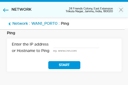
- Click Start.
- Click Traceroute on the Network Monitor screen to measure packet transit delays across the network.
- Enter a valid hostname or IP address in the field provided.

- Click Start.
Monitor WAN and LTE Status
You can view WAN and LTE status from the Network screen. WAN and LTE status can be on or off, up or down. Monitoring status is available only when the device is active.
To monitor WAN and LTE settings:
- Click the Monitor icon in the left menu bar to open the Monitor dashboard.
- Hover over the site in the honeycomb to open the option card for the device.
- Click Monitoring Dashboard in the Actions column of the device options card to display the Monitoring Dashboard screen.
- Click Network to open the Monitor screen to check the device network status.
- Click WAN or LTE and then click Access Circuit to view bandwidth usage for VPN (SD-WAN) and direct internet access (DIA).

- Click the menu bar at the bottom of the WAN or LTE screen to select a specific time frame to check access circuit bandwidth. The graph displays the BPS time interval in minutes, hours, and days:
- Last 15 minutes
- Last 30 minutes
- Last 1 hour
- Last 12 hours
- Last day
- Last 7 days
- Click OK to save the selection.
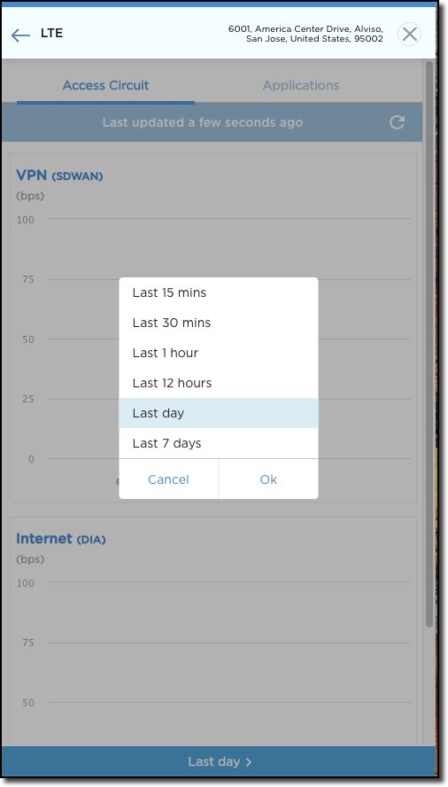
- Click WAN or LTE and then click Applications to view the application bandwidth used. The graph displays the BPS time interval in minutes, hours, and days. You can sort the following details in the pie chart:
- Application
- Session
- Bandwidth RX (bps)
- Bandwidth TX (bps)
- Click the menu bar at the bottom of the WAN or LTE screen to select a specific time frame to check access circuit bandwidth.
- Click OK to save the selection.

Monitor LAN Status
You use the Network screen to check the device's LAN status. LAN status can be on or off, up or down. The IP address is visible only when the interface is on.
To monitor LAN settings:
- Click the Monitor icon in the left menu bar to open the Monitor dashboard.
- Hover over the site in the honeycomb to display the device options card for the device.
- Click Monitoring Dashboard in the Actions column of the device options card to display the Monitoring Dashboard screen.
- Click Network to open the Monitor screen to check the device network status.

- In the LAN section, click Routes to check the status of the routing table. Use the Search feature to find a route.

- Click Ping to check whether the router is available and connected. Enter the following information.

Field Description Enter the IP Address or Hostname to Ping Enter a valid LAN IP address or hostname. Source Interface Select a LAN interface to run the ping test. If you do not select a source interface, the system selects any LAN port that is up. - Click Start. The ping summary is displayed.

- Click Done.
- Click Traceroute to measure packet transit delays across the network.
- Enter a valid hostname or IP address.

- Click Start. The traceroute output displays.
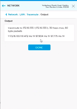
- Click Done.
Monitor Security Status
You use the Security screen to check the device URL category and reputation. To view the most current status, click the Refresh icon.
To monitor URL security status:
- Click the Monitor icon in the left menu bar to open the Monitor dashboard.
- Hover over the site in the honeycomb to open the option card for the device.
- Click Monitor Dashboard in the Actions column of the device-options card to open the Monitor screen.
- Click Security > URL Category to open the Security screen to view all sites that have been blocked (blacklisted). The type and number of blocked sites are listed in graph form in 7-day summary:
- Click the day of the week to view records specific to that day.
- Click Category and Count to view lists of browsed websites that have been blocked.
- Click the graph to check status in pie chart format.
- Click an item on the list to open the website details window. Details include To and From information and when the site was blocked.

- Click Security > URL Reputation to view URL risk levels in a pie chart. URL Reputation can be one of the following:
- High Risk IP Address
- Suspicious IP Address
- Moderate Risk
- Low Risk
- Trustworthy
Risk Hits and Percentage show statistics relating to information shown in the pie chart. Click the pie chart or the entries in the URL Reputation list to view individual website links.
- Click an item on the list to open the website details window. Details include To and From information and when the site was blocked.

Monitor Device Information
You use the Device screen to check the device CPU, disk, and memory status, SD-WAN connectivity, and bandwidth usage. To view the most current status, click Refresh.
To monitor device status:
- Click the Monitor icon in the left menu bar to open the Monitor dashboard.
- Hover over the site in the honeycomb to open the option card for the device.
- Click Monitor Dashboard in the Actions column of the device-options card to open the Monitor screen.
- Click Device to open the Device Information screen. Statistics automatically load showing overall device availability and CPU, disk, and memory use by percentage.

- Click CPU to view CPU usage in graph form in a new window.
- Click the menu bar at the bottom of the screen to select a specific time frame to capture CPU usage. Click OK to save the settings.
- Click the Refresh icon to update the screen.

- Click the Disk to view disk load usage in percentage form in a new window.
- Click the menu bar at the bottom of the screen to select a specific time frame to capture disk load. Click OK to save the settings.
- Click the Refresh icon to update the screen.

- Click Memory to view memory load in percentage form in a new window:
- Click the menu bar at the bottom of the screen to select a specific time frame to capture memory load. Click OK to save the settings.
- Click the Refresh icon to update the screen.

Monitor SD-WAN Connectivity
To monitor SD-WAN connectivity:
- Click the Monitor icon in the left menu bar to open the Monitor dashboard.
- Hover over the site in the honeycomb that you would like to monitor to open the option card for the device.
- Click Monitor Dashboard in the Actions column of the device-options card to open the Monitor screen.
- Click Device > SD-WAN Connectivity to view device connectivity status in a new window:
- Search for a device by name.
- Click the Refresh icon to update the screen.

Monitor Bandwidth Usage
To monitor device bandwidth:
- Click the Monitor icon in the left menu bar to open the Monitor dashboard.
- Hover over the site in the honeycomb that you would like to monitor to open the option card for the device.
- Click Monitor Dashboard in the Actions column of the device-options card to open the Monitor screen.
- Click Device > Bandwidth Usage to view device bandwidth status in a new window:
- Search for a device by name.
- Click the menu bar at the bottom of the screen to select a specific time frame to capture SD-WAN connectivity. Click OK to save the settings.
- Click the Refresh icon to update the screen.

Manage Device Analytics
Use the Versa Analytics (Deprecated) menu in the Settings to monitor the status of sites and devices connected to the Titan portal. View statistics about sites in the network and monitor network security from the Analytics dashboard, and view system logs for all connected devices. You can also build and manage reporting metrics from the Reporting screen, and view software version and system details from the Administration screen.
The following sections describe how to manage network and security analytics, build and manage reporting, and view device settings from the Analytics dashboard on the Titan portal.
Use the Analytics Dashboard
The Analytics dashboard displays analytics data in graphical representation. Sites and circuits connected to the Titan portal are sorted by bandwidth used and receive and transmit volume. Sites are also shown in map view. Click the menu icons in the site windows to set filter parameters, choose the type of display to use to view statistics, and to download and print statistic information.
To manage system status and activity from the Analytics dashboard:
- Click Settings > Versa Analytics (Deprecated) on the top-right side of the Titan Home page.

- Dashboard > System screen opens by default.
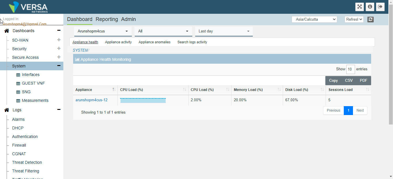
- View, sort, and filter analytics information in the statistics windows using the tools provided in the upper right corner of the windows.
- In the left menu bar, under Dashboards > SD-WAN, click one of the following to view statistics information in a new screen:
- Sites
- Sites Map
- Paths
View SD-WAN Analytics
To view analytics for SD-WAN connections from the Analytics dashboard:
- Click Settings > Versa Analytics (Deprecated) on the top-right side of the Titan Home page. The System Dashboard screen opens by default.
- In the left menu bar, under Dashboards > SD-WAN, click Sites to view statistics information in a new screen:
- Usage
- Availability
- Connections
- HeatMap
View Sites by Usage
View top site usage over time. Sort information using the drop-down menus provided at the top of the screen. View, sort, and filter analytics information using the tools provided in the upper right corner of the section. View sites in list form in the Sites section. Copy, download, or print the list using the tools provided in the upper right corner of the section.

View Sites by Availability
View top site availability over time. The Availability screen shows Down and Up status. Sort information using the drop-down menus provided at the top of the screen. Print analytics information using the tools provided in the upper right corner of the screen.

View Sites by Connection
View the top 50 site-to-site connections. The Connections screen shows analytics in a pie chart. Sort information using the drop-down menus provided at the top of the screen.

View Sites by Heat Map
View how much attention a site is getting by color code. Hover over the sections in the heat map to view site name, availability, and number of sessions. Print analytics information using the tools provided in the upper right corner of the screen.

View Sites and Circuits on the Site Map
To view the SD-WAN site map:
- Click Settings > Versa Analytics (Deprecated) on the top-right side of the Titan Home page. The System Dashboard screen opens by default.
- In the left menu bar, under Dashboards > SD-WAN, click Sites Map to view statistics information in the map. Click the Filter icon in the upper right corner to choose what the map displays:
- Clustered View
- Show Access Circuits

View Site Paths
To view site path analytics:
- Click Settings > Versa Analytics (Deprecated) on the top-right side of the Titan Home page. The System Dashboard screen opens by default.
- In the left menu bar, under Dashboards > SD-WAN, click Paths to view statistics information in a new screen.
- Usage
- SLA Metrics
- Rules
- MOS
View Paths by Usage
View top path usage by bandwidth over time (DualLTE). Sort information using the drop-down menus provided at the top of the screen. View, sort, and filter analytics information using the tools provided in the upper right corner of the section. Copy, download, or print the list using the tools provided in the upper right corner of the section.

View Paths by SLA Metrics
Take readings to monitor that the service being provided matches what is defined in the service contract. View top service-level agreement (SLA) metrics (DualLTE) by delay and by usage. Sort information using the drop-down menus provided at the top of the screen. View, sort, and filter analytics information using the tools provided in the upper right corner of the section. Copy, download, or print the list using the tools provided in the upper right corner of the section.

View Path Rules
View path rules (DualLTE) by bandwidth. Sort information using the drop-down menus provided at the top of the screen. View, sort, and filter analytics information using the tools provided in the upper right corner of the section. Copy, download, or print the list using the tools provided in the upper right corner of the section.

View Path MOS
View MOS score (DualLTE) statistics. Sort information using the drop-down menus provided at the top of the screen. View, sort, and filter analytics information using the tools provided in the upper right corner of the section. Copy, download, or print the list using the tools provided in the upper right corner of the section.

View Security Analytics
To view security analytics:
- Click Settings > Versa Analytics (Deprecated) on the top-right side of the Titan Home page. The System Dashboard screen opens by default.
- In the left menu bar, under Dashboards > Security, click Security to view the security analytics dashboard.
The following analytics information is displayed on the dashboard:
- Top Applications
- Top URL Categories
- Top Bandwidth Consuming Applications
- Top Rules
- Top Destination Addresses
- Top Source Addresses
- Top Zones
- Top Firewall Actions
- Top Threat Types
Hover over the windows on the Security dashboard to view statistic information.

- In the left menu bar, under Dashboards > Security, click a topic to view statistics information in a new screen.
- Applications
- Web
- Firewall
- Threats
View Security Applications
Application security describes security measures at the application level that aim to prevent data or code within the app from being stolen or hijacked.
To view security applications:
- Click Settings > Versa Analytics (Deprecated) on the top-right side of the Titan Home page. The System Dashboard screen opens by default.
- In the left menu bar, under Dashboards > Security, click Applications to view statistics information.

Sort information using the drop-down menus provided at the top of the screen. View, sort, and filter analytics information using the tools provided in the upper right corner of the section. Copy, download, or print the list using the tools provided in the upper right corner of the section.
View the following statistics on the Applications screen:
- Applications
- Risk
- Productivity
- Families
- Subfamilies
View Security Application Risk
Application risk assessment is the manual or automated analysis of an application's source code or architecture to determine the potential for any vulnerability. Sort information using the drop-down menus provided at the top of the screen. View, sort, and filter analytics information using the tools provided in the upper right corner of the section. Copy, download, or print the list using the tools provided in the upper right corner of the section.

View Security Application Productivity
Sort information using the drop-down menus provided at the top of the screen. View, sort, and filter analytics information using the tools provided in the upper right corner of the section. Copy, download, or print the list using the tools provided in the upper right corner of the section.

View Security Application Families
View security application types, or families, including networking, general internet, media, collaboration, and business systems. Sort information using the drop-down menus provided at the top of the screen. View, sort, and filter analytics information using the tools provided in the upper right corner of the section. Copy, download, or print the list using the tools provided in the upper right corner of the section.
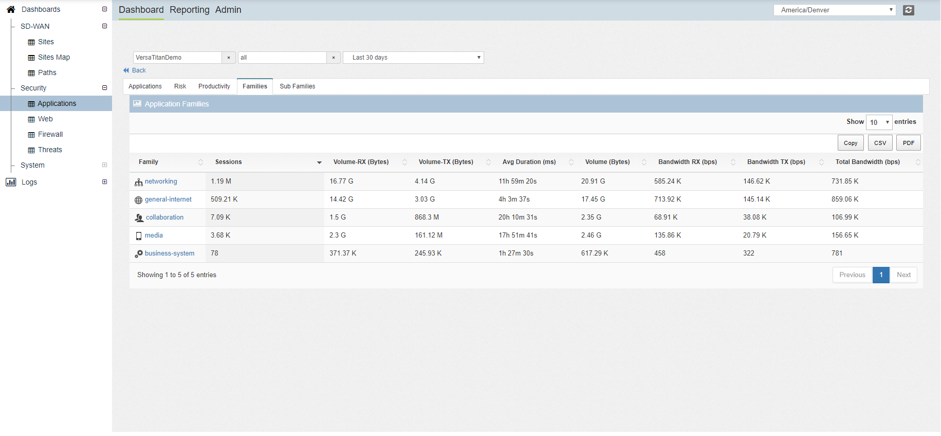
View Security Application Subfamilies
View additional categories of security application types, or subfamilies, including networking, network service, file server, audio-video, games, and more. Sort information using the drop-down menus provided at the top of the screen. View, sort, and filter analytics information using the tools provided in the upper right corner of the section. Copy, download, or print the list using the tools provided in the upper right corner of the section.
View Web Security
Web security analytics show how the URL categories and URL reputation settings are performing.
To view security analytics for current Internet settings:
- Click Settings > Versa Analytics (Deprecated) on the top-right side of the Titan Home page. The System Dashboard screen opens by default.
- In the left menu bar, under Dashboards > Security, click Web to view statistics information.
The following analytics information is displayed on the dashboard:
- URL Categories
- URL Reputation
View URL Category Analytics
Hover over the graph on the dashboard to view URL category usage over time. Sort information using the drop-down menus provided at the top of the screen. View, sort, and filter analytics information using the tools provided in the upper right corner of the section. Copy, download, or print the list using the tools provided in the upper right corner of the section.

View URL Reputation Analytics
Hover over the graph on the dashboard to view URL reputation usage over time. Sort information using the drop-down menus provided at the top of the screen. View, sort, and filter analytics information using the tools provided in the upper right corner of the section. Copy, download, or print the list using the tools provided in the upper right corner of the section.

View Firewall Analytics
Firewall analytics show how current security rules and IP settings are performing.
To view security analytics for current rules and IP settings:
- Click Settings > Versa Analytics (Deprecated) on the top-right side of the Titan Home page. The System Dashboard screen opens by default.
- In the left menu bar, under Dashboards > Security, click Firewall to view statistics information.
The following tabs are available on the dashboard:
- Rules
- Source
- Destination
- Zones
- Forwarding Class
View Rule Analytics
Hover over the graph on the dashboard to view rule usage over time. Sort information using the drop-down menus provided at the top of the screen. View, sort, and filter analytics information using the tools provided in the upper right corner of the section. Copy, download, or print the list using the tools provided in the upper right corner of the section.

View Source Analytics
Hover over the graph on the dashboard to view source IP usage over time. Sort information using the drop-down menus provided at the top of the screen. View, sort, and filter analytics information using the tools provided in the upper right corner of the section. Copy, download, or print the list using the tools provided in the upper right corner of the section.

View Destination Analytics
Hover over the graph on the dashboard to view destination IP usage over time. Sort information using the drop-down menus provided at the top of the screen. View, sort, and filter analytics information using the tools provided in the upper right corner of the section. Copy, download, or print the list using the tools provided in the upper right corner of the section.

View Zone Analytics
Hover over the graph on the dashboard to view zone usage over time. Sort information using the drop-down menus provided at the top of the screen. View, sort, and filter analytics information using the tools provided in the upper right corner of the section. Copy, download, or print the list using the tools provided in the upper right corner of the section.

View Forwarding Class Analytics
Forwarding classes (FCs) allow you to group packets for transmission and to assign packets to output queues. The forwarding class and the loss priority define the per-hop behavior (PHB in DiffServ) of a packet.
Hover over the graph on the dashboard to view forwarding class usage over time. Sort information using the drop-down menus provided at the top of the screen. View, sort, and filter analytics information using the tools provided in the upper right corner of the section. Copy, download, or print the list using the tools provided in the upper right corner of the section.

View Threat Analytics
Threat analytics show how current URL, IP, and malware settings are performing and summarize system vulnerabilities.
To view threat analytics:
- Click Settings > Versa Analytics (Deprecated) on the top-right side of the Titan Home page. The System Dashboard screen opens by default.
- In the left menu bar, under Dashboards > Security, click Threats to view statistics information.
The following tabs are available on the dashboard:
- Web
- IP
- Malware
- Vulnerabilities
- DDOS
- Summary
View Web Filtering Analytics
Hover over the windows on the dashboard to view URL filtering analytics. Sort information using the drop-down menus provided at the top of the screen. View, sort, and filter analytics information using the tools provided in the upper right corner of the section. Copy, download, or print the list using the tools provided in the upper right corner of the section.

View IP Filtering Analytics
Hover over the windows on the dashboard to view IP filtering. Sort information using the drop-down menus provided at the top of the screen. View, sort, and filter analytics information using the tools provided in the upper right corner of the section. Copy, download, or print the list using the tools provided in the upper right corner of the section.

View Malware Analytics
Hover over the windows on the dashboard to view antivirus and malware analytics. Sort information using the drop-down menus provided at the top of the screen. View, sort, and filter analytics information using the tools provided in the upper right corner of the section. Copy, download, or print the list using the tools provided in the upper right corner of the section.

View Vulnerability Analytics
Hover over the windows on the dashboard to view threat and vulnerability analytics. Sort information using the drop-down menus provided at the top of the screen. View, sort, and filter analytics information using the tools provided in the upper right corner of the section. Copy, download, or print the list using the tools provided in the upper right corner of the section.

View DDoS Analytics
Hover over the dashboard to view distributed denial-of-service (DDoS) attack analytics. Sort information using the drop-down menus provided at the top of the screen. View, sort, and filter analytics information using the tools provided in the upper right corner of the section. Copy, download, or print the list using the tools provided in the upper right corner of the section.

View a Summary of Threat Analytics
Hover over the windows in the dashboard to view top threat analytics. Sort information using the drop-down menus provided at the top of the screen. View, sort, and filter analytics information using the tools provided in the upper right corner of the section. Copy, download, or print the list using the tools provided in the upper right corner of the section.

View System Analytics
Use the Settings > Versa Analytics (Deprecated) > System dashboard to monitor device health.
To view device health monitoring:
- Click Settings > Versa Analytics (Deprecated) on the top-right side of the Titan Home page. The System Dashboard screen opens by default.
- In the left menu bar, under Dashboards, click System to view the System dashboard.
The following tabs are available on the dashboard:
- Interfaces
- Guest VNF
- SNG
Hover over the windows in the dashboard to view device health. Sort information using the drop-down menus provided at the top of the screen. View, sort, and filter analytics information using the tools provided in the upper right corner of the section. Copy, download, or print the list using the tools provided in the upper right corner of the section.

View System Interfaces
Use the Settings > Versa Analytics (Deprecated) > System > Interfaces dashboard to monitor WAN interfaces.
To view device interfaces:
- Click Settings > Versa Analytics (Deprecated) on the top-right side of the Titan Home page. The System Dashboard screen opens by default.
- In the left menu bar, under Dashboards, click System to view the System dashboard.
- Click Interfaces to view the following interfaces:
- WAN Interfaces
- LTE Interfaces
View WAN Interfaces
Hover over the windows in the dashboard to view WAN interface utilization. Sort information using the drop-down menus provided at the top of the screen. View, sort, and filter analytics information using the tools provided in the upper right corner of the section. Copy, download, or print the list using the tools provided in the upper right corner of the section.

View LTE Interfaces
Hover over the windows in the dashboard to view LTE interface statistics. Sort information using the drop-down menus provided at the top of the screen. View, sort, and filter analytics information using the tools provided in the upper right corner of the section. Copy, download, or print the list using the tools provided in the upper right corner of the section.

View Guest VNF Information
Use the Settings > Versa Analytics (Deprecated) > System > Guest VNF dashboard to monitor Guest VNF.
To view Guest VNF information:
- Click Settings > Versa Analytics (Deprecated) on the top-right side of the Titan Home page. The System Dashboard screen opens by default.
- In the left menu bar, under Dashboards, click System to view the System dashboard.
- Click Guest VNF to view the following:
- Guest VNF Health Monitoring
- Guest VNF Interface Statistics
- Guest VNF Events Logs

Hover over the windows in the dashboard to view Guest VNF information. Sort information using the drop-down menus provided at the top of the screen. View, sort, and filter analytics information using the tools provided in the upper right corner of the section. Copy, download, or print the list using the tools provided in the upper right corner of the section.
View Service Node Group Information
Use the Settings > Versa Analytics (Deprecated) > System > SNG dashboard to monitor service node groups (SNGs).
To view SNG information:
- Click Settings > Versa Analytics (Deprecated) on the top-right side of the Titan Home page. The System Dashboard screen opens by default.
- In the left menu bar, under Dashboards, click System to view the System dashboard.
- Click SNG to view SNG statistics.

View Logs
Use the Settings > Versa Analytics (Deprecated) > Logs dashboard to log information.
To view log information:
- Click Settings > Versa Analytics (Deprecated) on the top-right side of the Titan Home page. The System Dashboard screen opens by default.
- In the left menu bar, click Logs. The Logs > Alarms screen displays.

- Click additional log names to view information for those logs. The following logs are available:
- Alarms
- DHCP
- Authentication
- Firewall
- CGNAT
- DOS
- IDP
- Anti Virus
- URL Filtering
- IP Filtering
- Traffic Monitoring
- Web Monitoring
- SD-WAN
- Traffic Steering
- SSL Decryption
- ADC
- Guest VNF events
- Packet captures
Manage Device License Inventory
Use the Inventory dashboard to view device licenses and associated devices. You can turn service and security on or off. You can also perform the following tasks and Inventory actions from the dashboard:
- Management profile
- Custom logs profile
- SNMP Profile
- Create a spoke group
- Add a cloud account
- Undeploy a device
- Request device location
- Upload CA Certificates
- Deactivate a device
- Upgrade the software
The Inventory dashboard is available to the Enterprise Administrator; the Enterprise User does not have access to the Inventory dashboard.
Inventory data can be downloaded and exported in PDF and CSV format.
View Device Licenses
You can view a list of licenses used by activated devices or a list of all licenses. For Cloud Account/vCSG license information, see Configure a Branch in AWS.
To manage licenses and devices in the Titan Inventory:
- Click the Inventory icon in the left menu bar to open the Inventory dashboard.
- Select a device type in the Device Type field to view device licenses:
- Click Active Licenses to view active device licenses.
- Click Total Licenses to view all device licenses.
- Click SASE Gateway to view all SASE device licenses.

- Click the
 Select Display Fields icon to choose the columns to display in the Inventory section.

Field Description Service Type Display the series classification (CSG300, CSG00, or vCSG) and license type (such as CSG350-2LA).
Site Display the site location. Hover over the site name to view site address. Device Name Display the device name. Serial Number Display the serial number. S/W Version Display the VOS software version running on the device. Hover over S/W Version to view software information. Security Click the Security toggle to turn all device security components on or off. License Expiration Date Displays the date when the device license expires. Service State Click the Service State toggle to turn the service on or off. Action Click to select an inventory action. SPack Version Display the version of the installed security package (SPack).
The inventory dashboard uses the following naming conventions:
Acronym Description (blank) No WiFi and LTE WLA WiFi and LTE WLA-4GP WiFi, LTE, and four copper Gigabit Ethernet PoE ports 2LA No WiFi, two LTE 2LA-4GP No WiFi, two LTE, and four copper Gigabit Ethernet PoE ports
Add Custom Logs Profile
Titan Portal sends Syslog messages when the following match conditions are met:
- Firewall—Add security rules and select custom logs. For more information, see Manage Firewall Policies
- Steering—Add profile rules and select custom logs. For more information, see Create a Steering Profile
- Decryption—Add rule and select custom logs. For more information, see Configure TLS Decryption
To add customer flow logs profile in the Titan Inventory:
- Click the Inventory icon in the left menu bar to open the Inventory dashboard and click Management Profile at the top of the screen.

- In the Management Profile popup window, click Custom Logs Profile and enter the following information.

Field Description Profile Name Enter a name for the profile. IP Address Enter the IP address of the Syslog server. Click the + icon to add multiple IP addresses. Port Number Enter the port number. Protocol Select TCP or UDP. Log Type Select IPFIX or SYSLOG. Region Select a region. - Click Add. The flow log profile is displayed.
- Click the
 icon to edit the profile.
Add an SNMP Profile
You can configure SNMP at the branch level. You specify the SNMP version that the Titan device supports and the SNMP server to which the Titan device connects. You must configure an SNMP on at least one device to which the SNMP server is attached. For more information, see Configure ALG, SNMP, NTP, and Syslog (Miscellaneous Tab).
To add SNMP profile in the Titan Inventory:
- Click the Inventory icon in the left menu bar to open the Inventory dashboard, and then click Management Profile at the top of the screen.

- In the Management Profile popup window, click SNMP Profile and enter the following information.

Field Description Version Select the SNMP version. You can select one or more versions.
- v2c
- v3
Community For SNMPv2c, enter the SNMP community string to use to access the SNMP server. Username For SNMPv3, enter the username to use to access the SNMP server Password For SNMPv3, enter the password for the username. IP Address Enter the IP address of the SNMP server. Click the + icon to add multiple SNMP server IP addresses. - Click Save.
Create a Spoke Group
Spoke groups help to control direct traffic flow between the hubs, hub controllers, and specific branch spoke groups. You can create spoke groups templates on the Titan dashboard and bind them to specific spoke device templates to allow the devices to participate in a spoke group topology.
A spoke group network configuration can be of three types:
- Spoke to Hub—Set up a connection between a spoke and a hub. There is no communication between spokes, either directly or through a hub. This type of configuration is preferred when the hub is used as a gateway to go out from the spoke site.
- Spoke to Spoke via Hub—Set up a connection between two spokes through a hub. There is no communication between the spokes directly. The spokes have a default route towards the hub. Spokes are blocked from importing routes directly from other spoke sites.The hub receives the routes from the spoke and exports them to other spokes.
- Spoke to Spoke Direct—Set up a direct connection between two spokes within a spoke group, bypassing a hub. One spoke can receive LAN routes directly from the other spoke. For this spoke group type, you need to add a community value.
The spoke devices that are a part of the same spoke group inherit the properties of the group.
To create a spoke group:
- Click the Inventory icon in the left menu bar to open the Inventory dashboard.
- Click Spoke Group and enter the following information.

Field Description
Name Enter a name for the spoke group. Spoke Group Type Select the type of spoke group:
- Spoke to Hub Only
- Spoke to Spoke via Hub
- Spoke to Spoke Direct
- Community—Enter a community value.
Region Select the region in which to place hub and hub controller devices that facilitate spoke-to-hub to hub-to-spoke communication. Hub or Hub Controller Select hub or hub controller. Priority Select the priority of the hub. - Click Add.
Inventory Actions
To deactivate (remove), undeploy, request the location of a device, upload CA certificates, or software upgrades from the Inventory dashboard:
- Locate the device in the grid, then click the 3-dot icon in the Action column to display available actions.

- Click an action.
- Undeploy Device—Undeploys the device. The device and its configuration remain in the honeycomb.
- Request device location—Sends a notification on the mobile app to the user requesting the device location.
- Upload CA Certificates—Uploads key file, CA certificate file, and CA chain file.
- Deactivate—Removes the device, its site, and its configuration.
- Software Upgrades—Upgrades Spack, and download and upgrade the device software.
Note: You must wait for 5 minutes after undeploying a configuration before redeploying and activating an appliance. Titan must sync internal data structures when you undeploy; if this process is not complete you will receive an error message when you attempt to activate the appliance.
Upload a Certificate
A certificate authority (CA) is an entity that issues digital certificates that are used to verify the ownership of a public key. The digital certificates allow a party to trust the signature that is made by a private key that corresponds to the certified public key.
After a Titan device requests a certificate from a CA server, the CA server issues the certificate. You then need to upload the certificate to the CA database so that it can be used for verification.
Before you upload a CA certificate, you must upload a key file with the extension .key.
To upload a key file:
- Locate the device in the grid, and then click the 3-dot icon in the Action column to display available actions.

- Click Upload CA Certificates and then click Upload Key.

- In the Add Key popup window, enter the following information.
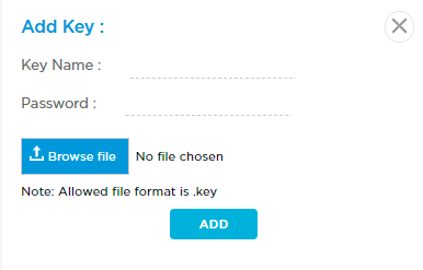
- Enter a key name and password.
- Click Browse file to select the key file to upload. The file must be in .key format.
- Click Add.
- Click Upload CA Certificates, and then click Upload Certificate.

- In the Add CA Certificate popup window, enter the following information.
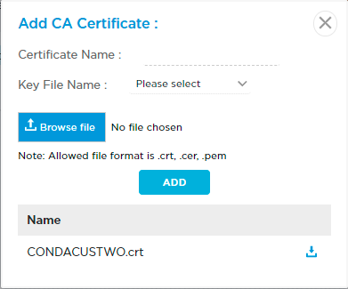
- Enter a certificate name.
- Select the key file name.
- Click Browse file to select the CA certificate file to upload. The file must be in .crt, .cer, or .pem format.
- Click Add. The certificate file is displayed.
- Click the
 icon to download the file. You need to install this certificate on your system to configure TLS decryption.
- Click Upload CA Certificates and then click Upload CA Chain.

- In the Add CA Chain popup window, enter the following information.
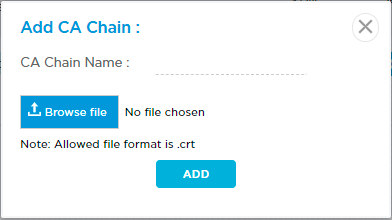
- Enter a CA chain name.
- Click Browse file to select the CA chain file to upload. The file must be in .crt format.
- Click Add.
Upgrade Software
To upgrade the software:
- Locate the device in the grid, and then click the 3-dot icon in the Action column to display available actions.
- Click Software Upgrades and then select an option from the following:

- Security Package—Upgrade the SPack on the device.
- Download to Device—Download the device software only to the selected device.
- Download and Upgrade Device—Download and upgrade the device software.
View Audit Logs
Audit logs provide details about API calls and responses. They include detailed information about every request that can be used for debugging. You can view and download the audit logs.
To view or download audit logs:
- Click Audit Logs in the left menu bar to display the Audit Logs dashboard.

You can perform the following actions from the audit logs dashboard:
- Clear—Click the
 icon to clear the logs.
 - Download—Click the
 icon to download the log file.
 - Refresh—Click the
 icon to refresh the audit logs window.
Manage Users
An operator, store administrator, MSP, reseller, or enterprise administrator can view, create, edit, and delete users and assign user roles and privileges from the Users dashboard. You cannot assign more privileges than the account you are using. Titan accounts allow access to both the Versa Titan portal and the Versa Titan mobile app.
For individual accounts, Titan Portal only displays permissible menu items. For example, the left menu bar may only display the Configure, Monitor, Troubleshoot, and Audit Logs icons for an Enterprise User account. Enterprise users do not have access to the Users module.
Manage User Accounts
To view a list of user accounts:
Click the Users icon in the left menu bar. The following screenshot displays the Users dashboard for an enterprise administrator login.

| Field | Description |
|---|---|
| Users |
Select a user from the Users drop-down list:
|
| Status | Displays whether the user is locked or unlocked. |
| Name | User's first and last name. |
| User email address. Initially matches username but can be edited. | |
| User Name | Username used to login to the account. This is the same as the initial email address for the account. |
| Phone | User phone number. |
| Role & Privileges | Displays the user role:
|
| Lock/Unlock | Click the toggle to lock or unlock the account. Locking the account disables the login without requiring you to delete the account. |
| 2FA | Slide the toggle to the left to disable or to the right to enable two-factor authentication. |
| Notification | Slide the toggle to the left to disable or to the right to enable mobile phone notifications. |
| Action | Click the 3-dot icon to choose an action:
|
Create a Store Administrator Account
An operator can create a store administrator account and assign user roles and privileges. You cannot assign greater privileges than the account you are using. A store administrator can log in to Titan Portal and can add other store administrators, MSPs, and resellers.
After you create a store administrator, a confirmation email is automatically sent to the email address that directs customers to the login screen and allows them to set their password. This email address automatically becomes the login name for the account.
To create a store administrator account:
- Log in to Titan Portal as an Operator, and create a new store administrator.
- Enter your username and password, and click Login.
- Click Users in the left menu bar to open the Users dashboard, and then click + Add User.

- Enter the following information.

Field Description First Name Enter the user's first name. Last Name Enter the user's last name. Email Address Enter an email address for the user. This automatically becomes the login name for the account. You can change the email address after creating the account but not the login name. Phone Number Select the country code and enter the phone number for the user. Titan Mobile pushes notifications to this phone number. Two Factor Authentication Slide the toggle to enable or disable two-factor authentication. Roles Select Store Admin.
Create as New Store Click to enter information for the new store. Store Enter new store name. Provider Name Enter VERSA. Deploy Click to create a new region on the Director node for the new store. Regions Click to select regions. You can select multiple regions attached to the Titan node. Allowed Product Select the products that the store can order:
- Cloud Appliances
- Versa Appliances
- Versa Cloud Gateway
- Versa Virtual Appliances
- White Box
Privileges Select the privileges:
- Manage Customer—Click to access the customer's organization.
- Manage Service—Click to access the dashboard and read and write customer networks or devices onboarded by this specific store admin.
- Click Create.
Create an MSP Account
An operator or store administrator can create an MSP account and assign user roles and privileges. You cannot assign greater privileges than the account you are using. An MSP can log in to Titan Portal and add other MSPs and resellers.
A confirmation email is automatically sent to the email address that directs customers to the login screen and allows them to set their password. This email address automatically becomes the login name for the account.
To create an MSP account:
- Log into Titan Portal as a Store Administrator.
- Enter your username and password, and click Login.
- Click Users menu in the left menu bar to open the Users dashboard, and then click + Add User icon.

- Enter the following information.

Field Description First Name Enter the first name for the MSP. Last Name Enter the last name for the MSP. Email Address Enter an email address for the MSP. This automatically becomes the login name for the account. You can change the email address after creating the account but not the login name. Phone Number Select the country code and enter the phone number for the MSP. Titan Mobile pushes notifications to this phone number. Two Factor Authentication Slide the toggle to enable or disable two-factor authentication. Roles Select Managed Service Provider (MSP).
Create as New MSP Click to enter information for the new MSP. MSP Enter a name for the MSP. Deploy Click to create a new region on the Director node for the MSP. Regions Click to select regions. If you are creating the MSP under the store admin that you have already created, the region that you selected while creating the store admin is automatically selected. Allowed Product Select the products that the MSP can order:
- Cloud Appliances
- Versa Appliances
- Versa Virtual Appliances
- Versa Cloud Gateway
- White Box
Privileges Select the privileges:
- Manage Customer—Click to access the customer's organization.
- Manage Service—Click to access the dashboard and read and write customer networks or devices onboarded by this specific MSP.
- Click Create.
To create a reseller from an MSP account, see Create a Reseller Account.
Create a Reseller Account
An operator, store administrator, or MSP can create a reseller account and assign user roles and privileges. You cannot assign greater privileges than the account you are using. A reseller can log in to Titan Portal and add other resellers.
A confirmation email is automatically sent to the email address that directs customers to the login screen and allows them to set their password. This email address automatically becomes the login name for the account.
To create a reseller account:
- Log into Titan Portal as an Operator, Store Administrator, or MSP.
- Enter your username and password, and click Login.
- Click Users icon in the left menu bar to open the Users dashboard, and then click + Add User icon.

- Enter the following information.

Field Description First Name Enter the first name for the reseller. Last Name Enter the last name the reseller. Email Address Enter an email address for the reseller. This automatically becomes the login name for the account. You can change the email address after creating the account but not the login name. Phone Number Select the country code and enter the phone number for the reseller. Titan Mobile pushes notifications to this phone number. Two-Factor Authentication Slide the toggle to enable or disable two-factor authentication. Roles Select the reseller. A reseller can create another reseller with the rights to select allowed products and assign privileges
Company Enter the name of the company. Deploy Click to create a new region on the Director node for the reseller. Regions Click to select regions. You can select multiple regions. Allowed Product Select the products that the reseller can order:
- Cloud Appliances
- Versa Appliances
- Versa Virtual Appliances
- Versa Cloud Gateway
- White Box
Privileges Select the privileges:
- Manage Customer—Click to access the customer's organization.
- Monitor Customer Network—Click to access the dashboard and read customer networks or devices onboarded by this specific reseller.
- Manage Service—Click to access the dashboard and read and write customer networks or devices onboarded by this specific reseller.
- Click Create.
To create another reseller from a reseller account:
- Log in to Titan Portal as a reseller.
- Enter your username and password, and click Login.
- Click Users icon in the left menu bar to open the Users dashboard, and then click + Add User icon.
- Enter the following information.

Field Description First Name Enter the first name for the reseller. Last Name Enter the last name for the reseller. Email Address Enter an email address for the reseller. This automatically becomes the login name for the account. You can change the email address after creating the account but not the login name. Phone Number Select the country code and enter the phone number for the reseller. Titan Mobile pushes notifications to this phone number. Two-Factor Authentication Slide the toggle to enable or disable two-factor authentication. Allowed Product Select the allowed products:
- Cloud Appliances
- Versa Appliances
- Versa Virtual Appliances
- Versa Cloud Gateway
- White Box
Privileges Select the privileges:
- Manage Customer—Click to access Shop.
- Monitor Customer Network—Click to access the dashboard and read customer networks or devices onboarded by this specific reseller.
- Manage Service—Click to access the dashboard and read and write customer networks or devices onboarded by this specific reseller.
- Click Create.
Add an Enterprise User
An enterprise administrator can add a new account and assign user roles and privileges. You cannot assign more privileges than the account you are using. Titan Portal automatically sends an email to the user with instructions on creating an account password and downloading Titan Mobile. Users can use their accounts to log in to both Titan Portal and Titan Mobile.
To add a new user:
- Click the Users icon in the left menu bar to display the Users dashboard.
- Click Users drop-down list and select Titan User.
- Click the + Add User icon at the top right to display the Add User window.

- Enter information for the following fields.
Field Description First Name Enter the user's first name. Last Name Enter the user's last name. Email Address Enter an email address for the user. This automatically becomes the login name for the account. You can change the email address after creating the account but not the login name. Phone Number Select the country code and enter the phone number for the MSP. Titan Mobile pushes notifications to this phone number. Two Factor Authentication Slide the toggle to enable or disable two-factor authentication.
Role Click Enterprise Admin or Enterprise User to assign a role to the account.
- Enterprise Admin
Enterprise Admin roles have the following privileges:

- Read and write access to WAN, LTE, LAN, WiFi, Security, and Steering settings.
- Read access to Versa Director, Versa Analytics, Audit Logs, and Titan shop.
By default, enterprise administrators have the following privileges:
- Read access to monitor, troubleshoot, inventory, and users menu items.
- Write access to WiFi radio settings and read-only access to all other configuration settings.
- Can create a new site.
- Can create new user accounts but cannot assign more privileges to an account than they have themselves.
- Enterprise User
Enterprise User roles have the following privileges:
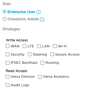
- Read and write access to WAN, LTE, LAN, WiFi, Security, Steering, Secure Access, IPsec Backhaul, and Routing settings.
- Read access to Versa Director, Versa Analytics, and Audit Logs.
By default, enterprise users have the following privileges:
- Read access to monitor and troubleshoot menu items.
- Write access to WiFi radio settings and read-only access to all other configuration settings.
- Click Create to add the new user.
Add a Titan Secure VPN Service User
An enterprise administrator can add a new account for Titan secure VPN service user.
To add a new Titan secure VPN service user:
- Click the Users icon in the left menu bar to display the Users dashboard.
- Click Users drop-down list in the main pane and select Titan Secure VPN Service User.

Field Description Users Select a user from the Users drop-down list:
- Titan User
- Titan Secure VPN Service User
Licenses Displays the license information:
- Total
- Used
Import Users Click
 icon to import users from an Excel template.

- Click Browse file icon and select the Excel template.
- Click Upload.
Name User's first and last name. Email User email address. Initially matches username but can be edited. Phone User phone number. Action Click the 3-dot icon to choose an action:
- Edit a user
- Delete a user
- Click the
 icon at the top right to display the Add User window.

- Enter information for the following fields.
Field Description First Name Enter the user's first name. Last Name Enter the user's last name. Email Address Enter an email address for the user. This automatically becomes the login name for the account. You can change the email address after creating the account but not the login name. Phone Select the country code and enter the phone number for the MSP. Titan Mobile pushes notifications to this phone number. -
Click Create.
Edit a User
The enterprise admin can edit user information and change roles and privileges assigned to a user.
To edit a user:
- Click the Users icon in the left menu bar to display the Users dashboard.
- Hover over the 3-dot menu in the user Actions column and click Edit to display the Edit User window.

- Edit the information as needed in the fields provided.
- Click Enterprise User or Enterprise Admin to change roles.
- Check or uncheck boxes to change Privileges.
- Click Update to save the settings.
Delete a User
The enterprise admin can delete users from the Titan Users dashboard. Deleting an account with an active login automatically logs out the user.
To delete a user:
- Click the Users icon in the left navigation menu bar to display the Users dashboard.
- Hover over the 3-dot menu in the user Actions column and click Delete.
- Click Yes in the pop-up window to delete the user, or click No to return to the Users dashboard without deleting the user.
Export Account Information
To export account details to a file in PDF, CSV, or XLS format:
- Click the Users icon in the left navigation menu bar to display the Users dashboard.
- Click the
 Export icon to display a drop-down menu.
 - Select PDF, CSV, or XLS, then use the pop-up window specific to your operating system to save the file.
Troubleshoot the Titan Portal
You can troubleshoot the following issues from the Titan portal:
- Cannot connect to the internet
- Cannot connect to WiFi
- Slow internet connection
- Cannot access certain websites
Use Troubleshooting Tools
To use troubleshooting tools on the Titan portal:
- Click the Troubleshoot icon in the left menu bar to open the troubleshooting dashboard.
- Hover over the site in the honeycomb that you would like to troubleshoot to open the option card for the device.

- Click Troubleshoot in the Actions column of the device-options card to open the Troubleshoot screen.
- Choose a troubleshooting option from the Troubleshoot screen:
- Cannot connect to the Internet
- Cannot connect to Wi-Fi
- Slow Internet connection
- Cannot access some websites

Cannot Connect to the Internet
If you cannot connect to the Internet:
- Click the Troubleshoot icon in the left menu bar to open the troubleshooting dashboard.
- Hover over the site in the honeycomb that you would like to troubleshoot to open the option card for the device.
- Click Troubleshoot in the Actions column of the device-options card to open the Troubleshoot screen.
- Click Cannot connect to the Internet to open the Troubleshoot screen to begin checking the connection:
- Make sure the device is powered up and that the Ethernet cable is connected to WAN1 or WAN2.
- Make sure the SIM card is inserted if you are using LTE for internet connectivity.

- Click Check Connection to check network connectivity to the router.
If the router is reachable, the system shows that connectivity is successful. If the device is reachable, you have the option to click Go to Configure or Back to Troubleshoot.

If the device is not reachable, you have the option to click Try Again or Manually Reset Device. Note that you can click Try Again several times to attempt to reach the device. If attempts are not successful, physically reset the device.

Physically Reset a Device
When you physically reset device, you switch the router power to off for approximately 30 seconds, and then turn router power on. Note that by resetting the device, all connected devices are temporarily disconnected.
Click Manually Reset Device to access the Manual Reset screen and follow directions on the screen to physically reset the router.

Cannot Connect to WiFi
If you cannot connect to WiFi:
- Click the Troubleshoot icon in the left menu bar to open the troubleshooting dashboard.
- Hover over the site in the honeycomb that you would like to troubleshoot to open the option card for the device.
- Click Troubleshoot in the Actions column of the device-options card to open the Troubleshoot screen.
- Select Cannot connect to Wi-Fi to open the Troubleshoot screen to check WiFi connection.

- Click Check Wi-Fi Settings to verify WiFi status on the Wireless Networks troubleshooting screen:
- Corporate Wi-Fi—Click the toggle to enable Corporate WiFi, or click to open the Edit Wireless Networks window to update settings.
- Guest Wi-Fi—Click the toggle to enable Guest WiFi, or click to open the Edit Wireless Networks window to update settings.

- Click Publish to update the changes on the router.
You can also choose to reset the device.
Restore Default Device Settings
If you cannot connect to WiFi from the Wireless Networks screen, you can reset the device to default settings. When you reset a device, all clients connected to the WiFi and intranet lose connectivity while the router reboots. It can take up to 3 minutes for the connection to resume. When reboot is complete, wait another 3 to 5 minutes for the router to become active.
To reset the device:
- Click the Troubleshoot icon in the left menu bar to open the troubleshooting dashboard.
- Hover over the site in the honeycomb that you would like to troubleshoot to open the option card for the device.
- Click Troubleshoot in the Actions column of the device-options card to open the Troubleshoot screen.
- Select Cannot connect to Wi-Fi to open the Troubleshoot screen to reset the device.
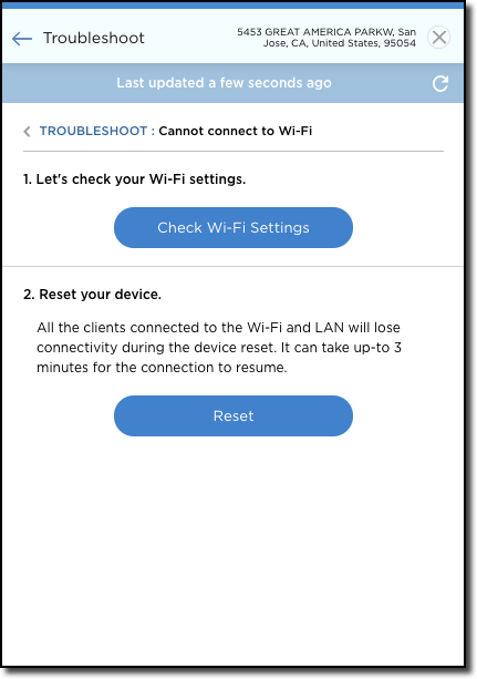
- Click Reset to open the Reset screen.

- Click Continue to initiate device reset. Wait for the device to reboot and reconnect to WiFi.
Slow Internet Connection
You can view internet and internet backup (LTE) settings and run a test to check internet connectivity speed on reachable online devices from the Speed Test screen. If PPPoE is available for WAN interfaces, you can run a speed test for those devices from this screen.
Run speed tests approximately one minute apart. The system issues an alert if speed tests are performed too closely together or if a speed test has been issued from another device simultaneously. The system allows you to run a maximum of 20 speed tests in a single 24-hour period.
To initiate an internet connectivity speed test on the Titan portal:
- Click the Troubleshoot icon in the left menu bar to open the troubleshooting dashboard.
- Hover over the site in the honeycomb that you would like to troubleshoot to open the option card for the device.
- Click Troubleshoot in the Actions column of the device-options card to open the Troubleshoot screen.
- Select Slow Internet connection to open the Troubleshoot screen to check slow Internet connection.

- Click Run Speed Test to open the Speed Test screen to check the speed of the WAN port.

- Select a WAN interface from the Select Interface drop-down menu.
- Click Continue.

- To run a speed test on the internet connection for the WAN interface, click the Internet icon and then click Test.
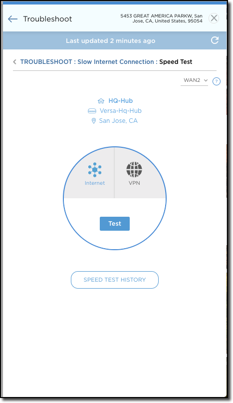
- Click the VPN icon to run a speed test on the VPN connection:
- Search for a device by site name or zip code in the field provided.
- Click to select the device.
- Click Test.

Click the Reload icon to refresh any device connected to the internet to troubleshoot connectivity. Wait one minute, then tap Start Speed Test again to check for updated status.
The following is an example of speed test results when checking devices for slow internet connection.

Click Speed Test History to view the complete speed test history for the device. Tap Clear History to clear speed test history.

View Internet Backup Signal Strength
If LTE backup is available, signal strength is displayed on the Speed Test screen. Signal strength above >65 is considered strong; a signal below this value is considered weak.
Note that you cannot run a speed test on LTE backup.
To check LTE Internet backup signal strength on the Titan portal:
- Click the Troubleshoot icon in the left menu bar to open the troubleshooting dashboard.
- Hover over the site in the honeycomb that you would like to troubleshoot to open the option card for the device.
- Click Troubleshoot in the Actions column of the device-options card to open the Troubleshoot screen.
- Select Slow Internet connection to open the Troubleshoot screen to check slow Internet connection.
Tap Reload to refresh any device connected with LTE internet backup to troubleshoot connectivity. Wait one minute, then tap Start Speed Test again to check for updated status.
Slow Internet Connection
If you are experiencing slow internet connection, you can check that the network is up and that LTE Internet backup is not slowing the connection.
To check the connection:
- Click the Troubleshoot icon in the left menu bar to open the troubleshooting dashboard.
- Hover over the site in the honeycomb that you would like to troubleshoot to open the option card for the device.
- Click Troubleshoot in the Actions column of the device-options card to open the Troubleshoot screen.
- Select Slow Internet connection to open the Troubleshoot screen to check slow Internet connection.

- Click Network to check settings on the Network screen.

- Click Routes to check the status of the router routing table. Use the Search feature to find a route.

- Click Ping to check that the router is available and connected.
- Enter a valid host name and IP address in the fields provided.
- Click Start.

- Click Traceroute to measure packet transit delays across the network.
- Enter a valid host name and IP address in the field provided.
- Click Start.

Cannot Access Certain Websites
If you cannot access certain websites:
- Click the Troubleshoot icon in the left menu bar to open the troubleshooting dashboard.
- Hover over the site that you would like to troubleshoot to open the option card for the device.
- Click Troubleshoot in the Actions column of the device-options card to open the Troubleshoot screen.
- Select Cannot access some websites to open the Troubleshoot screen to check website accessibility.
- Choose an option from the Troubleshoot screen:
- Check Blacklisted sites
- Add sites to Whitelist
- IP Reputation
- URL Category

Checking Blacklisted Sites
- Click Check Blacklisted Sites to add websites that you would like to block on the network. To block multiple websites, separate each URL with a comma.

- Click Publish to save the settings to the router.
Add Sites to the Whitelist
- Click Add Sites to Whitelist to add websites to always allow on the network, even if they are blocked by other settings. To add multiple websites, separate each URL with a comma.

- Click Publish to save the settings to the router.
Configure IP Address Reputation
- Click IP Reputation to open the Reputation Level screen.
- Select device IP reputation level settings. Click the down arrow in the left column to display a description of each category.:
- High Risk IP Addresses
- Suspicious IP Addresses
- Moderate Risk
- Low Risk
- Trustworthy

- Click one of the 3 icons in the right column for each category to select a reputation level for that category:
- Blocked (red)
- Ask (amber)
- Allowed (blue)
- Click Publish to save the settings to the router.
Configuring the URL Category
- Click URL Category to open the URL category screen.
- Click one of the boxes next to each name to adjust the URL filtering category. Click Information for a description of each category:
- Blocked
- Alert & Confirm

- Click Publish to save the settings to the router.
Contact Support
Contact Versa support for assistance from any screen by clicking the Help icon.
Supported Software Information
Releases 9.1.1 and later support all content described in this article.


