Configure EVPN VXLAN for SD-WAN
![]() For supported software information, click here.
For supported software information, click here.
You can configure virtual extensible LAN (VXLAN) on Versa Operating SystemTM (VOSTM ) devices. VXLAN is a data plane encapsulation protocol that allows you to run Layer 2 Ethernet VPN (EVPN) over a Layer 3 IP network using standard VXLAN encapsulation over UDP. In multitenant and cloud environments, VXLAN allows a network to handle much larger traffic loads than traditional VLANs while providing the same traffic isolation and segmentation as classic VLANs.
For more information about EVPN, see RFC 7432, BGP MPLS-Based Ethernet VPN.
For more information about EVPN VXLAN, see RFC 8365, A Network Virtualization Overlay Solution Using Ethernet VPN (EVPN).
Note that the terminology in the article aligns with that used in the RFCs, which defines EVPNs in of provider edge (PE) routers. However, the VOS SD-WAN EVPN VXLAN solution is for customer edge (CE) devices for both service providers and enterprises.
Overview
VXLAN works in both the control plane and the data plane.
In the control plane, MP-BGP, which supports the Layer 2 VPN Address Family Identifier (AFI) and the EVPN Subsequent Address Family Identifier (SAFI), allows a provider edge (PE) device to distribute MAC addresses and IP routing information to another PE device.
In the data plane, the Layer 2 MAC frame is encapsulated in an 8-byte VXLAN header with a 24-bit VXLAN network identifier (VNI) that designates the individual VXLAN overlay network, the UDP protocol (port 4789), and the outer IP address (destination/source IP addresses of the tunnel endpoint), thus providing a way to reach the destination MAC address.
VXLAN encapsulation and decapsulation is performed at VXLAN tunnel endpoints (VTEPs). There is one VTEPs at the origin of a VXLAN tunnel and a second VTEP at the termination point of the tunnel. A VTEP can be a physical or virtual end host or a network device, such as a router or switch.
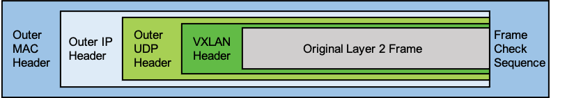
A VXLAN packet has the following format, which is illustrated in the following figure:
- Outer MAC header—14 bytes (4 optional)
- Outer IP header—20 bytes
- Outer UDP header—8 bytes
- VXLAN header—8 bytes
VLAN-to-VXLAN Mapping
To map a VLAN to a VXLAN, a regular VLAN is mapped to a unique 24-bit VNI ID so that it can be used throughout a network. You specify the VNI ID as part of the bridge domain configuration. In addition to the regular BGP control plane information, such as the route distinguisher (RD) and the route target (RT), the local MAC addresses that belong to a bridge domain on a PE device are distributed to other PE devices by attaching the VNI to the MAC routes in the control plane. Using the route distinguisher, VNI, and route target, the MAC addresses are imported into the correct MAC-VRF (routing instance) and bridge domain. A MAC-VRF is a VRF table for installing MAC addresses on a PE device for a tenant.
Note: In an EVPN multihoming context, the BGP EVPN route distinguisher should be different for VTEP endpoints that have the same ESI values.
When a MAC frame is destined to a remote MAC address in a MAC-VRF and bridge domain, it is encapsulated with the correct VNI ID in the VXLAN header. The receiving PE device uses the VNI ID to look up the correct MAC-VRF and bridge domain, and then the MAC address are forwarded to the correct local interface in the MAC-VRF.
Although published standards allow you to use different VNI IDs for the same VLAN on different PE devices, the VOS implementation maps the VLANs and VNI IDs consistently across all PE devices.
EVPN Service Types
The VOS software supports the following EVPN service types:
- VLAN based—Map a single VNI to an EVPN instance (EVI), maintain a MAC table for that VNI, and set the Ethernet tag ID in all EVPN routes to 0. In the data plane, the ingress device does not include an inner VLAN tag in the encapsulated frame, and the egress device discards frames that have an inner VLAN tag.
- VLAN-aware bundle—Map multiple VNIs to an EVI, maintain a separate bridge table for each VNI, and set the Ethernet tag ID in all EVPN routes to the VNI (global VNI case). In the data plane, the VNI is used to identify the bridge table, the ingress device does not include an inner VLAN tag in the encapsulated frame, and the egress device discards frames that have an inner VLAN tag.
EVPN Route Types
The VOS software supports the following EVPN route types, as specified in RFC 7432:
- Type 1—Ethernet autodiscovery (AD) routes. These routes are advertised only if the Ethernet segment identifier (ESI) is set to a nonzero value, which means that Type 1 routes originate for multihomed sites only. If a customer edge (CE) device is single-homed, the ESI value is 0.
- Type 2—MAC/IP advertisement routes. EVPN allows an end host’s IP and MAC addresses to be advertised within the EVPN network layer reachability information (NLRI), which allows the control plane to learn an end system's MAC address. VOS devices support MAC route advertisement.
- Type 3—Inclusive multicast Ethernet tag routes. These routes set up a path for broadcast, unknown, and multicast (BUM) traffic from a local PE device to a remote PE device on a per-VLAN, per-ESI basis. The information in Type 3 advertisements allows an ingress router to deliver BUM traffic to the other PE devices that are part of an EVPN instance. VOS devices support ingress replication.
- Type 4—Ethernet segment routes. These routes are used in multihoming scenarios, to elect the designated forwarder (DF) and to allow a CE device to be multihomed to two or more PE devices in either single-active or active–active mode. PE devices that are connected to the same Ethernet segment discover each other by using Ethernet segment routes.
- Type 5—IP prefix route. These routes are used to advertise EVPN routes using IP prefixes and decouple the IP prefix advertisements from the MAC/IP advertisement routes in EVPN (specified in RFC 9136).
BUM Traffic Handling
BUM traffic is handled using ingress replication on the ingress PE node. The flood tag, which is the VNI used to reach a remote PE device for BUM traffic, is essentially the same as the VNI used for unicast traffic. The receiving PE device uses the VNI to identify the virtual switch (MAC-VRF) and bridge domain so that it can flood BUM traffic into that bridge domain.
Note: For BUM traffic handling, an ingress replication list supports a maximum of 64 EVPN neighbors.
Configure EVPN VXLAN
To configure EVPN VXLAN, you do the following:
- Configure a virtual switch (MAC-VRF) with a VNI.
- Configure the EVPN service.
Configure a Virtual Switch with a VNI
To configure a virtual switch (MAC-VRF) with a VNI:
- In Director view:
- Select the Configuration tab in the top menu bar.
- Select Templates > Device Templates in the horizontal menu bar.
- Select an organization in the left menu bar.
- Select a post-staging template. The view changes to Appliance view.
- Select the Configuration tab in the top menu bar.
- Select Networking > Virtual Switches in the left menu bar. The main pane displays a list of the virtual switches that are already configured.
- Click the
 Add icon. In the Configure Virtual Switch popup window, select Virtual Switch Details in the left menu bar, then enter an instance name in the field provided.
 - Select EVPN in the left menu bar.
- In the Encapsulation field, select VXLAN.

- Select Virtual Switch Details in the left menu bar to configure the VXLAN VNI.

- In the Bridge Domains group of fields, click the Add icon. In the Add Bridge Domains popup window, enter information for the following fields.
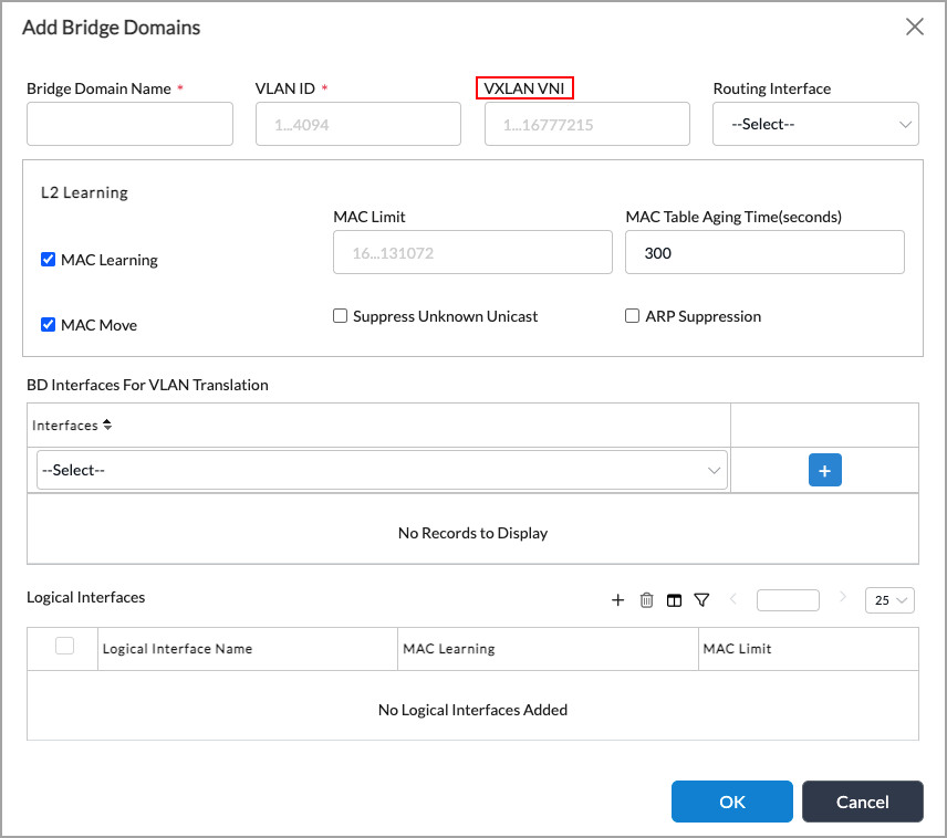
Field Description Bridge Domain Name (Required) Enter a name for the bridge domain. VLAN ID (Required) Enter a VLAN ID for the bridge domain. VXLAN VNI
Enter a number for the VXLAN VNI ID.
Range: 1 through 16777215
Default: None - Click OK Add Bridge Domains screen, the click OK in the Configure Virtual Switch screen.
Configure the EVPN Service
- In Director view:
- Select the Configuration tab in the top menu bar.
- Select Templates > Device Templates in the horizontal menu bar.
- Select an organization in the left menu bar.
- Select a post-staging template. The view changes to Appliance view.
- Select the Configuration tab in the top menu bar.
- Select Networking > Virtual Switches in the left menu bar. The main pane displays a list of the virtual switches that are already configured.
- Click the Add icon. In the Configure Virtual Switch popup window, select Virtual Switch Details in the left menu bar, and enter information for the following fields.
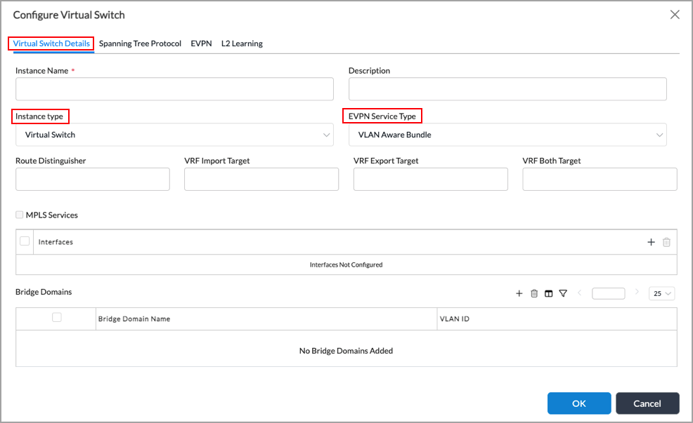
Field Description Instance Name (Required) Enter a name for the virtual switch instance. Instance Type Select Virtual Switch. EVPN Service Type Select the service type:
- VLAN—Map a single VLAN to an EVI.
- VLAN-Aware Bundle—Map multiple VLANs to an EVI.
- Click OK.
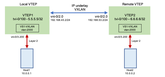
Example Configuration
This section provides an example of configuring EVPN VXLAN using the topology illustrated in the following figure. In this example, Host1 connects to the local virtual switch VS1-VXLAN, which is VTEP1 and has an IP address of 5.5.5.5/32. Host2 connects to the remote virtual switch VS1-VXLAN, which is VTEP2 and has an IP address of 6.6.6.6/32. Host1 and Host2 both belong to VLAN 2000. For Host1 to communicate with Host2, VTEP1 needs to connect to VTEP2 over a VXLAN tunnel in the IP underlay network.
Configure Tunnel Virtual Interfaces on VTEP1 and VTEP2
First, you configure the transport network (underlay) virtual router and its neighbor PE devices (5.5.5.5 and 6.6.6.6). These PE devices are the remote virtual tunnel endpoint (VTEP) addresses for the EVPN VXLAN network. The EVPN local router address represents the local VTEP address for the EVPN VXLAN network. The transport virtual router should also have a tunnel virtual interface (TVI) to represent the local VTEP with the appropriate tunnel type. (For more information about configuring interfaces, see Configure Interfaces).
In this example topology, tvi-0/100 on local VTEP1 peers with tvi-0/100 on remote VTEP2. The tunnel is a standard point-to-multipoint VXLAN tunnel. You configure the static routes on the subinterfaces and provide the reachability information for the neighboring VTEP.
- Configuration for tvi-0/100 on local VTEP1, whose IP address is 5.5.5.5/32:

- Configuration for tvi-0/100 on remote VTEP2, whose IP address is 6.6.6.6/32:


Add TVI Interfaces To Identify Organization Traffic
To properly identify tenant traffic, you include the VXLAN TVI in the organization (tenant) configuration. Without the tenant identification, traffic forwarding does not work on the TVI.
To add the VXLAN TVI interface to the organization:
- In Director view:
- Select the Configuration tab in the top menu bar.
- Select Devices > Devices in the horizontal menu bar.
- Select an organization in left navigation panel.
- Select a tenant or Controller node in the main pane. The view changes to Appliance view.
- Select the Configuration tab in the top menu bar.
- Select Others > Organization > Limits in the left menu bar.
- Select the tenant or provider organization in the main pane.
- In the Edit Organization Limit popup window, click the Add icon and add tvi-0/100.0.

- Click OK.
Enable the EVPN Core and Add the TVI Interface to the Transport Virtual Router
- In Director view:
- Select the Configuration tab in the top menu bar.
- Select Templates > Device Templates in the horizontal menu bar.
- Select an organization in left navigation panel.
- Select a post-staging template in the main pane. The view changes to Appliance view.
- Select the Configuration tab in the top menu bar.
- Select Networking > Virtual Routers in the left menu bar.
- Click the Add icon. In the Edit WAN3-Transport-VR popup window, select Virtual Router Details in the left menu bar.

Configure BGP
Next, you configure BGP on the local router (VTEP1) and the remote router (VTEP2).
Configure BGP on the Local Router
On the local router (VTEP1), you configure a peer relationship between the local loopback interface (tvi-0/100) and the remote loopback interface (tvi-0/100) on the remote router (VTEP2).
- In Director view:
- Select the Configuration tab in the top menu bar.
- Select Templates > Device Templates in the horizontal menu bar.
- Select an organization in left navigation panel.
- Select a post-staging template in the main pane. The view changes to Appliance view.
- Select the Configuration tab in the top menu bar.
- Select Networking > Virtual Routers in the left menu bar.
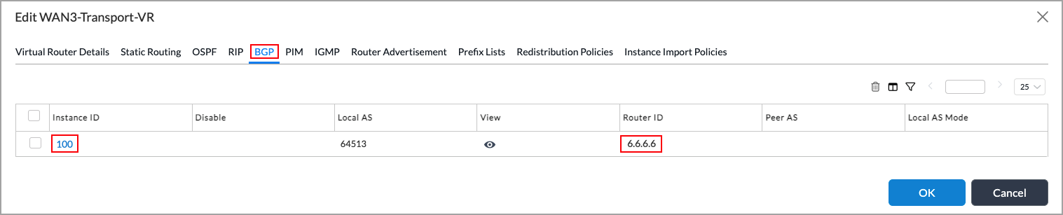
- Click the Add icon. In the Edit WAN3-Transport-VR popup window, select BGP in the left menu bar.

- Select the instance ID that corresponds to the local router. The Edit BGP Instance popup window displays.
- Select the General tab, and configure the following information:


- Select the Peer Group tab, and select the peer group instance name that corresponds to the remote router.
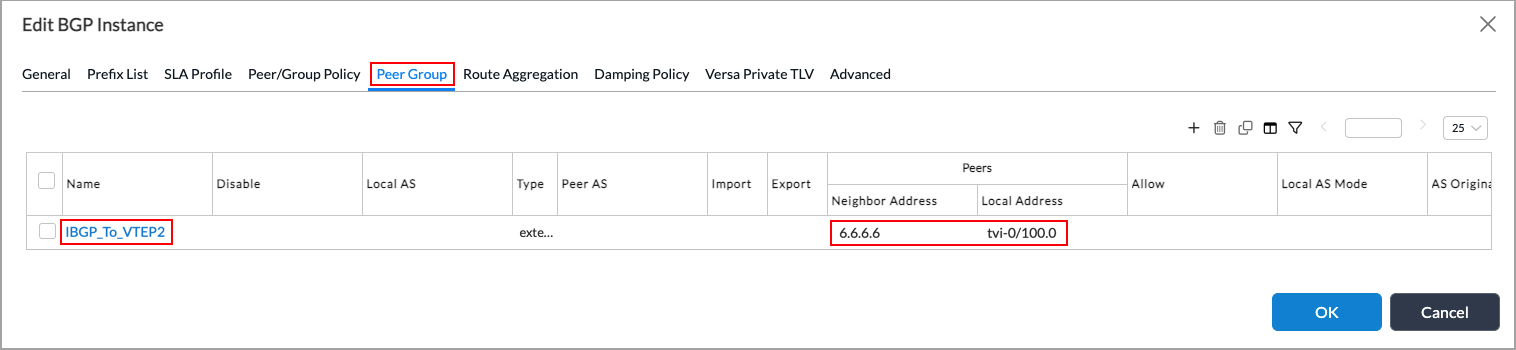
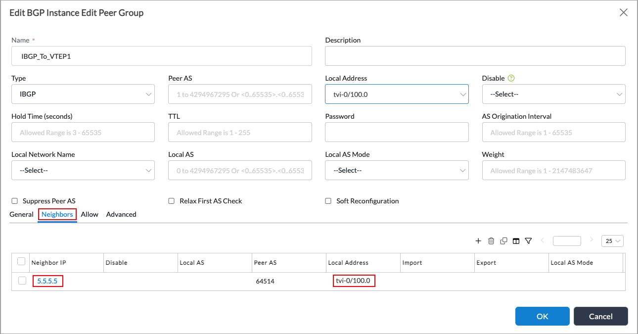
- In the Edit BGP Instance Edit Peer Group popup window, select the General tab, and configure the following information:

- In the Edit BGP Instance Edit Peer Group popup window, select the Neighbors tab, and configure the following information:

- Select the neighbor, and in the Edit BGP Instance Edit Peer Group popup window, select the Neighbors tab and Edit Neighbor, and enter the following information:

- Click OK twice.
Configure BGP on the Remote Router (VTEP2)
On the remote router (VTEP2), you configure a peer relationship between the remote loopback interface (tvi-0/100) and the loopback interface (tvi-0/100) on the local router (VTEP2).
- In Director view:
- Select the Configuration tab in the top menu bar.
- Select Templates > Device Templates in the horizontal menu bar.
- Select an organization in left navigation panel.
- Select a post-staging template in the main pane. The view changes to Appliance view.
- Select the Configuration tab in the top menu bar.
- Select Networking > Virtual Routers in the left menu bar.
- Click the Add icon. In the Edit WAN3-Transport-VR popup window, select BGP in the left menu bar.
- Select the instance ID that corresponds to the local router. The Edit BGP Instance popup window displays.
- Select the General tab, and enter the following information:

- Select the Peer Group tab, and select the peer group instance name that corresponds to the local router.

- In the Edit BGP Instance Edit Peer Group popup window, select the General tab and configure the following information.

- Select the Neighbors tab, and configure the following information:
- Select the neighbor, and in the Edit BGP Instance Edit Peer Group popup window, select the Neighbors tab and Edit Neighbor, and enter the following information.

- Click OK twice.
Configure Virtual Switch Instances VTEP1 and VTEP2
Finally, you configure the virtual switch instances VTEP1 and VTEP2.
Configure VS1-VXLAN (VTEP1)
Configure the local virtual switch VS1-VXLAN VTEP1, whose IP address is 5.5.5.5:
- In Director view:
- Select the Configuration tab in the top menu bar.
- Select Templates > Device Templates in the horizontal menu bar.
- Select an organization in left navigation panel.
- Select a post-staging template in the main pane. The view changes to Appliance view.
- Select the Configuration tab in the top menu bar.
- Select Networking > Virtual Switches in the left menu bar.
- Click the Add icon. In the Edit VS1_VXLAN popup window, select Virtual Switch Details in the left menu bar.
- Enter the following information.

- Click OK.
Configure the VLAN-to-VXLAN VNI Mapping for VTEP1
Configure the VLAN-to-VXLAN VNI mapping for VTEP1:
- In Director view:
- Select the Configuration tab in the top menu bar.
- Select Templates > Device Templates in the horizontal menu bar.
- Select an organization in left navigation panel.
- Select a post-staging template in the main pane. The view changes to Appliance view.
- Select the Configuration tab in the top menu bar.
- Select Networking > Virtual Switches in the left menu bar.
- Select a virtual switch, and edit it. In the Edit Bridge Domains popup window, enter the following information:

- Click OK.
Map VS1-VXLAN to the the EVPN Core Instance for VTEP1
- In Director view:
- Select the Configuration tab in the top menu bar.
- Select Templates > Device Templates in the horizontal menu bar.
- Select an organization in left navigation panel.
- Select a post-staging template in the main pane. The view changes to Appliance view.
- Select the Configuration tab in the top menu bar.
- Select Networking > Virtual Switches in the left menu bar.
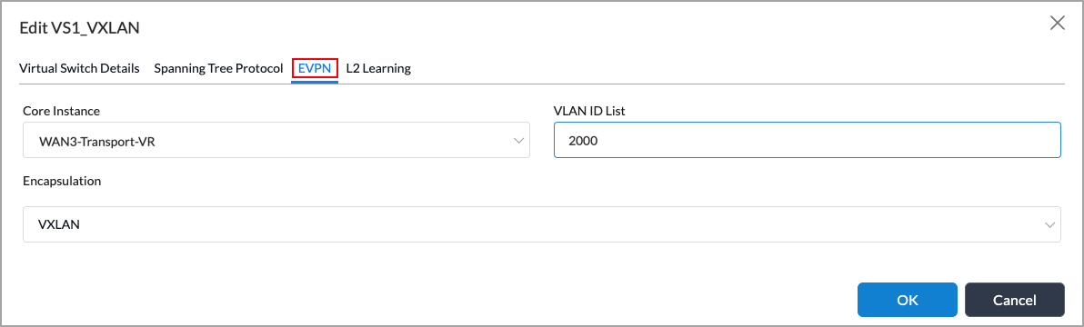
- Select the VS1_VXLAN, and in the Edit VS1-VXLAN popup window, select EVPN in the left menu bar. Enter the following information:
- Click OK.
Configure VS1-VXLAN (VTEP2)
Configure the remote virtual switch VS1-VXLAN VTEP2, whose IP address is 6.6.6.6:
- In Director view:
- Select the Configuration tab in the top menu bar.
- Select Templates > Device Templates in the horizontal menu bar.
- Select an organization in left navigation panel.
- Select a post-staging template in the main pane. The view changes to Appliance view.
- Select the Configuration tab in the top menu bar.
- Select Networking > Virtual Switches in the left menu bar.
- In Transport-WAN-VR, select VS1_VXLAN.
- In the Edit VS1_VXLAN popup window, select Virtual Switch Details in the left menu bar, and enter the following information:
- Click OK.
Configure the VLAN-to-VXLAN VNI Mapping for VTEP2
- In Director view:
- Select the Configuration tab in the top menu bar.
- Select Templates > Device Templates in the horizontal menu bar.
- Select an organization in left navigation panel.
- Select a post-staging template in the main pane. The view changes to Appliance view.
- Select the Configuration tab in the top menu bar.
- Select Networking > Virtual Switches in the left menu bar.
- Select a virtual switch, and edit it. In the Edit Bridge Domains popup window, enter the following information:
- Click OK.
Map VS1-VXLAN to the EVPN Core Instance (VTEP2)
- In Director view:
- Select the Configuration tab in the top menu bar.
- Select Templates > Device Templates in the horizontal menu bar.
- Select an organization in left navigation panel.
- Select a post-staging template in the main pane. The view changes to Appliance view.
- Select the Configuration tab in the top menu bar.
- Select Networking > Virtual Switches in the left menu bar.
- Select the VS1_VXLAN, and in the Edit VS1-VXLAN popup window, select EVPN in the left menu bar. Enter the following information:
- Click OK.
Verify the EVPN VXLAN Configuration
- In Director view, select the Monitor tab in the top menu bar.
- Select the organization in the left menu bar.
- Select the Devices tab in the horizontal menu bar.

- Select a device in the main pane.
- Select the Networking tab, then select Switching.
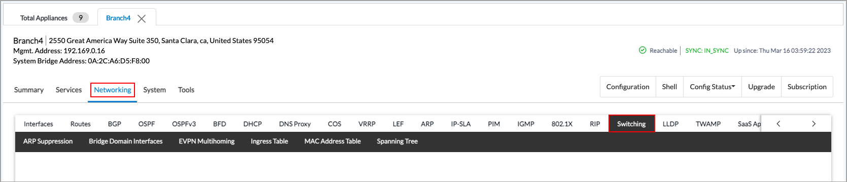
- Select the MAC Address Table in the horizontal menu bar.
- Select a switch name from the first drop-down list.
- Select a VLAN from the second drop-down list.
- Select the type of output to display from the third drop-down list, either Brief (default) or Statistics. The screen displays bridge MAC table information for VXLAN. The following screenshot shows the dtvi-0/440 bridge domain interface connected to the remote branch/VTEP at Branch2.

- Select the Ingress Table tab to display the remote VXLAN tunnel endpoints. The following screenshot shows the interface VLAN 1.

Supported Software Information
Releases 21.2.1 and later support all content described in this article, except:
- Releases 22.1.1 and later support EVPN type 5 routes.
Additional Information
Configure EVPN Multihoming for SD-WAN
Configure EVPN Multihoming for Hosts Using ZT-LAN
Configure EVPN VXLAN for ZT-LAN
Configure Interfaces
Configure Layer 2 Forwarding
RFC 7432, BGP MPLS-Based Ethernet VPN
RFC 8365, A Network Virtualization Overlay Solution Using Ethernet VPN (EVPN)