Configure Hierarchical Scheduling
![]() For supported software information, click here.
For supported software information, click here.
Hierarchical scheduling is a traffic management feature that enables control of packet scheduling across different layers of the network hierarchy. It allows administrators to define scheduling policies at the port, queue group, and individual queue levels, ensuring the precise allocation of bandwidth and priority among various traffic classes. Organizing schedulers in a hierarchical structure provides granular traffic shaping and fair resource distribution, and is particularly useful in complex networks where traffic control must align with both physical and logical service models.
Hierarchical scheduling supports both scheduling and shaping configurations across multiple levels of the scheduler hierarchy, allowing flexible and customizable traffic management in accordance with user-defined policies and network design requirements.
Note: Although hierarchical scheduling is supported on both wired and wireless components, it currently applies only to wired traffic.
Hierarchical scheduling is supported on the following hardware platforms:
- Cloud Services Switch 2000 Series
- Cloud Services Gateway 3000 Series
- Cloud Services Switch 4000 Series
- Cloud Services Switch 8000 Series
Configure Hierarchical Scheduling on NPU Interfaces
To configure hierarchical scheduling, you configure schedulers and scheduler maps. Schedulers consist of nodes and queues, where queues act as traffic termination points and nodes serve as intermediate decision stages. Each scheduler supports configuration parameters such as scheduling mode, weight, and shaping-rate.
The scheduler-map allows you to define a hierarchy of schedulers, reflecting the hardware-based scheduling structure within the NPU. Each scheduler map specifies the hierarchy level, identifies child schedulers or nodes, and maps them to specific interfaces. The scheduler-map assigns the schedulers to a traffic class and enforces differentiated QoS behavior across traffic classes.
You attach the scheduler map to an NPU interface. Hierarchical scheduling is supported exclusively on NPU physical interfaces and is not applicable to NPU shared interfaces or internal NPU links.
Configure Schedulers
- In Director view:
- Select the Configuration tab in the top menu bar.
- Select Template > Device Templates in the left menu bar.
- Select an organization in the Organization field.
- Select a template in the main pane. The view changes to Template view.
- Select Configuration > Networking > NPU > Class of Service > Schedulers in the left menu bar.

- Click the
 Add icon. The Add Scheduler screen displays. Enter information for the following fields.

Field Description Name (Required) Enter a name for the scheduler. Description (Optional) Enter a text description of the scheduler. Mode (Required) Select a scheduler mode. The options are:
- SP—Strict Priority
- WRR—Weighted Round Robin
- DWR— Deficit Weighted Round Robin
Weight (For WRR and DWR mode only.) Set the transmission rate of data packets.
- SP—Not configurable. The SP weight is 0.
- WRR—Weighted Round Robin
Range: 1 through 100 - DWR— Deficit Weighted Round Robin
Range: 1 through 100
Shaping Rate (Group of Fields) - Scheduler Transmit Rate (PIR) Kbps
Enter the Peak Information Rate (PIR). PIR is the maximum rate of traffic that can pass through an interface, in kilobits per second (Kbps). The PIR value must be equal to or greater than the CIR value.
Range: 0 through 4294967295 Kbps
Default: None
- Scheduler Committed Rate (CIR) Kbps
Enter the Committed Information Rate (CIR) in kilobits per second (Kbps). CIR is the average rate of traffic that can pass through an interface.
Range: 0 through 4294967295 Kbps
Default: None
Configure Scheduler Maps
- In Director view:
- Select the Configuration tab in the top menu bar.
- Select Templates > Device Templates in the left menu bar.
- Select an organization in the Organization field.
- Select a template in the main pane. The view changes to Template view.
- Select Configuration > Networking > NPU > Class of Service > Scheduler Maps in the left menu bar.

- Click the Add icon. The Add Scheduler Map screen displays. Enter information for the following fields.

Field Description Name (Required) Enter a name for the scheduler map. Description (Optional) Enter a text description of the scheduler map. Level Select a child scheduler-map level from the drop-down list. The options are:
- 0 (Set)
- 1 (Group)
- 2 (CoS)
Child Scheduler Select a child scheduler from the drop-down list. Node ID Enter the node ID for the scheduler. Scheduler Select a scheduler from the drop-down list. - Click OK.
Attach a Scheduler Map to an Interface
- In Director view:
- Select the Configuration tab in the top menu bar.
- Select Templates > Device Templates in the left menu bar.
- Select an organization in the Organization field.
- Select a template in the main pane. The view changes to Template view.
- Select Configuration > Networking > NPU > Class of Service > Interface/Network in the left menu bar.

- Select the Interface horizontal sub-tab, then click the Add icon. The Add Interface screen displays. Enter information for the following fields.
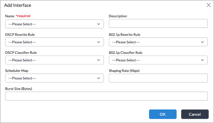
Field Description Name (Required) Select the name of an interface. Description (Optional) Enter a text description for the interface or network. DSCP Rewrite Rule (Available only for VNI interfaces, TVI interfaces, and network associations.) Select the Differentiated Services Code Point (DSCP) rewrite rule to use for the egress traffic, which rewrites the DSCP code points of packets before forwarding the packets.
802.1p Rewrite Rule Select the 802.1p rule to use for the egress traffic, which rewrites the 802.1p code points of Ethernet packets before forwarding the packets.
DSCP Classifier Rule Select the DSCP classifier rule to use, which classifies traffic into forwarding classes and assigns loss priorities to the traffic based on DSCP bits.
802.1p Classifier Rule Select the 802.1p classifier rule to use, which classifies Ethernet traffic into forwarding classes and assigns loss priorities to the traffic based on 802.1p code point bits.
Scheduler Map Select the scheduler map to use for the egress traffic.
Shaping Rate (Kbps)
Enter the shaping rate, in Kbps.
Range: 8 through 200000000 Kbps
Default: NoneBurst Size (Bytes)
Enter the burst size, in bytes.
Range: 256 through 100000000 bytes
Default: Depends on the link speed of the underlying interface. For example, if you connect two 1-GB interfaces, the burst size is 125000 bytes. If you connect a 1-GB interface to a 100-MB interface, the link speed is autonegotiated to 100 MB and the burst size is automatically set to 12500 bytes, and if you connect a 1-GB to a 10-MB interface, the burst size is automatically set to 1250 bytes.For most cases, it is recommended that you do not change the interface's burst size. However, you might consider changing it when the interface has autonegotiated a smaller burst size, but you know that the link can handle a larger higher burst. For example, if a 1-GB interface has autonegotiated to 10 MB, and if you know that the hardware can handle a burst of 125000 bytes and that the other side of the line can handle that much incoming burst, you could configure a larger burst.
- Click OK.
Verify Hierarchical Scheduling
To verify schedulers at the NPU schedulers organization level:
admin@DUT1-cli(config)% show orgs org-services Tenant1 npu class-of-service schedulers
schedulers default {
    weight 1;
    mode   WRR;
}
schedulers video {
    weight 20;
    mode   WRR;
}
schedulers voice {
    weight 0;
    mode   SP;
}
To verify schedulers at the NPU interface organization level:
admin@DUT1-cli(config)% show orgs org-services Tenant1 npu class-of-service interfaces
enet-0/44.1 {
    dscp-classifier-rule QClass;
}
enet-0/46 {
    scheduler-map L0Map;
}
[ok][2025-11-07 05:29:56]

[edit]
To verify scheduler maps at the NPU schedulers organization level:
admin@DUT1-cli(config)% show orgs org-services Tenant1 npu class-of-service scheduler-maps
scheduler-maps L0Map {
    level 0;
    child-scheduler L1Map;
}
scheduler-maps L1Map {
    level 1;
    child-scheduler L2Map;
}
scheduler-maps L2Map {
    node-id 0 {
        scheduler default;
    }
    node-id 1 {
        scheduler default;
    }
    node-id 2 {
        scheduler default;
    }
    node-id 3 {
        scheduler default;
    }
    node-id 4 {
        scheduler voice;
    }
    node-id 5 {
        scheduler default;
    }
    node-id 6 {
        scheduler video;
    }
    node-id 7 {
        scheduler default;
    }
}
Example Use Cases
This section shows multiple configuration options to achieve prioritization of voice traffic (q4) over video traffic (q6) and default (best-effort) traffic (q0) using the NPU’s hierarchical scheduling capabilities. The examples demonstrate how different scheduling modes and parameters, such strict priority (SP), WRR weights, and WRR with shaping (CIR/PIR) affect overall traffic fairness, latency, and bandwidth distribution.
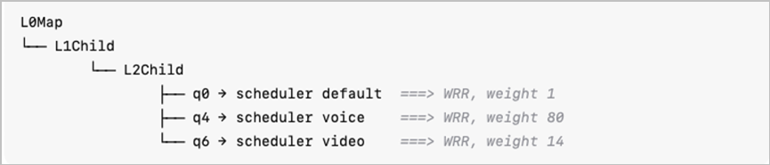
All options use the same three level scheduler hierarchy:

Example 1: Strict Priority (SP) for Voice
The objective of this example is to provide absolute priority to voice traffic, ensuring lowest latency and jitter for real-time applications. It is recommended to use SP when voice traffic must always be served first, regardless of other flows.
- Configuration:
- Voice queue (q4) is configured as Strict Priority (SP).
- Video (q6) and default (q0) use WRR scheduling with lower weights.
- Example Mapping:

- Behavior:
- SP ensures that voice traffic (q4) is always serviced before any other queue as long as it has traffic to send.
- Guarantees minimal delay and jitter for voice but can starve lower-priority queues (video and default) under high voice load.
- Best suited for critical real-time services with low-bandwidth but strict latency requirements.
- Pros: Absolute priority for voice.
- Cons: Risk of starvation for other queues during congestion.
Example 2: WRR with High Weight for Voice
The objective of this example is to use WRR weights to achieve prioritization while maintaining fairness and preventing starvation. It is recommended to use WRR with high weights for priority with fairness.
- Configuration: All traffic classes use WRR, with weights reflecting their relative importance.
- Example Mapping:
Behavior:
- WRR serves queues proportionally to their assigned weights.
- Voice traffic (q4) is scheduled most frequently, but video and default traffic still receive service.
- Suitable for networks where voice is important but not critical enough for strict priority.
- Pros: Maintains fairness; no starvation.
- Cons: Voice latency may slightly increase under heavy load compared to SP mode.
Example 3: WRR + Shaping (CIR/PIR)
The objective of this example is to combine WRR scheduling with CIR/PIR shaping to enforce guaranteed minimum rates while maintaining fairness under congestion. It is recommended to use WRR with shaping for guaranteed bandwidth allocation and optimal fairness under congestion for balanced QoS.
- Configuration: All traffic classes use WRR, with weights and CIR/PIR, reflecting their relative importance.
- Example Mapping:

If only weights are defined without shaping parameters (CIR/PIR):
- WRR schedules traffic based purely on relative weights.
- Under congestion, high-weight queues (like voice) can consume most of the available bandwidth, leaving little or no capacity for others.
- This can cause bandwidth starvation for low-weight queues (e.g., q0).
Combining WRR with shaping provides a more balanced and controlled behavior.
|
Option |
Voice Priority Method |
Fairness |
Latency |
Bandwidth Control |
Risk of Starvation |
|---|---|---|---|---|---|
|
SP for Voice |
Absolute (Strict Priority) |
Low |
Lowest |
No shaping |
High (for q0, q6) |
|
WRR (High Weight for Voice) |
Proportional (Weight-based) |
Medium |
Low |
No shaping |
Medium |
|
WRR + Shaping (CIR/PIR) |
Weighted + Rate-based |
High |
Low |
Guaranteed |
None |
Supported Software Information
Releases 23.1.2 and later support all content described in this article.