
CSX1000 Series Hardware Guide
At a Glance
The Versa Cloud Services Switch (CSX) 1000 series appliances are next-generation software-defined switching platform and access layer appliances that combine an Ethernet switch chipset with an x86-based processor subsystem. CSX1000 series switches deliver carrier-grade reliability, line-rate Ethernet switching, and built-in x86-based computational power to provide enterprise-grade routing, SD-LAN services, and integrated security.
CSX1000 series appliances run Versa Operating System™ (VOS™) software, which provides comprehensive integrated security, including the following:
- Next-generation firewall (NGFW), unified threat management (UTM), and zero-trust network access (ZTNA)
- On-premises ZTNA
- Next-generation software-defined access
- Fully secure software-defined perimeter
- Application intelligence and application policy-based forwarding capabilities
- Line-rate Layer 2 and Layer 3 forwarding and switching
- Scalable advanced routing
- Genuine multitenancy
- Big-data–based analytics
The CSX1000 series appliances with VOS software are ideal for enterprise branch and campus LAN edge deployments, offering natively built-in security and connectivity capabilities. The appliances enable secure, scalable, and reliable enterprise-wide LAN networking solutions.
Versa Networks management and control software, including Versa Director, Concerto orchestrator, and Versa Analytics, support CSX1000 series appliances. Versa Director and Concerto orchestrator support configuration, monitoring, and provisioning of CSX1000 series appliances. Versa Analytics provides device, network, and security analytics. Managed service providers (MSPs) and enterprises of all sizes can deploy CSX1000 series appliances for scalable managed services.
CSX1000 series appliances deliver carrier-grade reliability, high performance, line-rate Ethernet switching, and high computational capacity for enterprise-grade routing, ZT-LAN, next-generation security, on-premises ZTNA, and inline device auto discovery scenarios. They are designed for deployment in small to medium size enterprise branches, campus sites, and data centers that require advanced secure SD-WAN along with comprehensive advanced application and cloud-intelligent SD-WAN services on-premises.
CSX1000 series appliances offer LAN edge or access and high-speed uplink ports to provide non-blocking, high-performance LAN solutions. CSX1000 switching ports are highly scalable, and the Ethernet switch chipset provides single-rate Gigabit Ethernet and multi-rate Gigabit Ethernet ports with built-in Power over Ethernet+ (PoE+) capabilities. CSX1000 LAN edge Ethernet switches offer 25/10 Gigabit Ethernet and 100 Gigabit Ethernet to provide high-speed connectivity to other network elements in the LAN environment.
CSX1000 series appliances have x86 processor computational capacity and high-capacity memory and storage that allow you to run VOS stateful functions in highly scalable forms. You can use the built-in computational capacity to host third-party virtual machines (VMs) and simplify network deployments, eliminating the need for consolidating multiple appliances and functions, such as additional compute blades, other standalone hardware platforms, and separate firewalls.
CSX1000 series appliances integrate a TPM chip with cryptographic acceleration to ensure the integrity and security of data, such as encryption and authentication keys. CSX1000 series appliances have a secure BIOS and secure boot capabilities.
CSX1000 series appliances provide the following networking and management interface features:
Networking interfaces
- Ethernet switching
- 12 1-Gigabit Ethernet PoE+ (30 W) ports for LAN edge/access interfaces for CSX1100
- 24 1-Gigabit Ethernet PoE+ (30 W) ports for LAN edge/access interfaces for CSX1200
- Four multi-rate 5/2.5/1-Gigabit Ethernet ports
- Two 10-Gigabit Ethernet SFP+ ports
Management interfaces
- One Gigabit Ethernet-over-copper dedicated management port
- One RJ45 RS232 console port
- One USB port
- PoE source support on all copper ports
- Fixed, single AC power supply
- Side-to-side cooling
CSX1000 Appliance Models
The CSX1000 series appliances are available in CSX1100 and CSX1200 models.
Chassis Views
Figure 1 and Figure 2 show the front and rear panels of the CSX1100 appliance.
Figure 1: Front Panel of the CSX1100 Appliance

Figure 2: Rear Panel of the CSX1100 Appliance

Figure 3 and Figure 4 show the front and rear panels of the CSX1200 appliance.
Figure 3: Front Panel of the CSX1200 Appliance

Figure 4: Rear Panel of the CSX1200 Appliance
Front and Rear Panel Components
This article describes the front and rear panel components of a Cloud Services Switch (CSX) 1000 series appliance.
Front Panel
The front panel of a CSX1100 series appliance has a power button, a reset button, and four status LEDs for power, status, cloud, and GPS as shown in Figure 1.
Figure 1: Front Panel of a CSX1100 Appliance

Figure 2 shows the front panel of a CSX1200 appliance.
Figure 2: Front Panel of a CSX1200 Appliance

LEDs
Status LEDs provide the operational status of the appliance, interfaces, WLAN, and LTE connections.
Table 1 lists the LEDs, their colors and states, and the status they indicate.
Table 1: Front Panel LEDs in a CSX1000 Series Appliance
| LED | Color | Status |
|---|---|---|
| Power | Green |
|
| Status | Green, Red |
|
| Cloud | Green, Red |
|
| GPS | White |
|
Power Button
Pressing the power on/standby button on the front panel of a CSX1000 series appliance turns on the power.
To turn the power off, use one of the following methods:
- Press and release the power on/standby button. This method initiates a controlled shutdown of applications and the operating system before the appliance enters standby mode.
- Press and hold the power on/standby button for 4 seconds or more. This method forces the appliance to enter standby mode without exiting the application and the operating system. If an application stops responding, you can use this method to force a shutdown.
Reset Button
The Reset button on the front panel of a CSX1000 series appliance resets the appliance to the factory-default settings. The reset functionality depends on the number of times you press the button within a span of 30 seconds, as described in Table 3. In between each press of the reset button, you must pause for a second for the key press to register.
The Reset button is recessed so that it is not accidentally pressed while the appliance is operational. To press the Reset button, use a sharp, narrow tool.
Table 3: Reset Button Press Behavior
| Number of Presses | Behavior |
|---|---|
| 2 | Reset the appliance to the factory-default snapshot. |
| 4 | Reset the appliance to the branch prestaging configuration. |
| 6 | Reset the appliance to the branch staging configuration. |
| 8 | Reset the appliance to the branch post-staging configuration. |
Reset the Appliance from the CLI
You can reset the appliance to the factory-default configuration by issuing the request system reset CLI command. To do this, you first connect to the appliance through the serial console port or by using SSH.
The factory-default reset procedure can take up to 20 minutes to complete. Do not power off the appliance during this time.
To reset an appliance to the factory-default configuration:
- Connect to the appliance using one of the following methods:
- To connect to the appliance through the serial console port, see Configure a Management Console to Connect to a CSX1000 Appliance.
- To connect to the appliance using SSH:
- Connect your PC to the management port of the appliance. The management port has the default static IP address 10.10.10.10/24.
- Configure the PC IP address to any IP from this segment, for example, 10.10.10.1/24.
- Open an SSH session to the appliance using its IP address, 10.10.10.10.
- Log in to the appliance. Please consult Versa Networks technical support for default credentials.
- Start the CLI:
$ cli
- Enter the configure command to switch to configuration mode. The prompt changes to %.
- Issue the following command to reset the configuration to the factory default. If the current software version on the appliance is the same as that of the factory reset snapshot, the procedure takes about 10 minutes to complete. If the software versions are different, the procedure takes about 20 minutes to complete. Do not power off the appliance during the process.
% request system reset
- Verify that all Versa services are running by issuing the vsh status command from the Linux bash CLI. The following is a sample output of this command. If all the services are shown as stopped, issue the vsh start command from the Linux bash CLI to start them manually.
# vsh status
versa-service    is Running, [*] process 6784
versa-infmgr     is Running, [-] process 5623
versa-rfd        is Running, [-] process 5838
versa-vmod       is Running, [-] process 5839
versa-ip2user    is Running, [-] process 5844
versa-imgr       is Running, [-] process 5848
versa-acctmgrd   is Running, [-] process 5845
versa-fltrmgr    is Running, [-] process 5648
versa-vstated    is Running, [-] process 5625
versa-addrmgrd   is Running, [-] process 5857
versa-rt-cli-xfm is Running, [-] process 5798
versa-rtd        is Running, [-] process 5827
versa-dhcpd      is Running, [-] process 5620
versa-eventd     is Running, [-] process 5843
versa-vrrpd      is Running, [-] process 5643
versa-dnsd       is Running, [-] process 5646
versa-ppmd       is Running, [-] process 5793
versa-snmp-xform is Running, [-] process 5800
versa-certd      is Running, [-] process 5849
versa-ntpd       is Running, [*] process 5612
versa-dhclient6  is Running, [-] process 5807
versa-redis      is Running, [-] process 6927
versa-av-redis   is Running, [-] process 5003
versa-spackmgr   is Running, [-] process 5832
versa-monit      is Running, [*] process 6078
versa-confd      is Running, [*] process 4798
versa-fail2ban   is Running, [*] process 6093
versa-auditd     is Running, [*] process 6116
versa-nodejs     is Running, [-] process 5775
- Power off the appliance:
# sudo poweroff
Rear Panel
The rear panel of a CSX1000 series appliance has a C14 AC inlet. Figure 3 shows the rear panel of a CSX1000 series appliance.
Figure 3: Rear Panel of the CSX1000 Series Appliance

Install a CSX1000 Series Appliance
This article provides instructions about how to unpack a Cloud Services Switch (CSX) 1000 series appliance and how to install it.
CSX1000 series appliances have integrated faceplate rack-mount ears for installation into standard 19-inch racks. When you install a CSX1000 series appliance in a 19-inch rack, allow a minimum of 1-RU space on each side of the appliance to allow hot air to flow out of the appliance.
When placing a CSX1000 series appliance on a desk, ensure that the vents on the side of the unit are never blocked, to allow hot air to flow out of the appliance. Covering the vents prevents heat from dissipating out of the appliance, which can cause the chassis to overheat and then shut down.
Unpack a CSX1000 Series Appliance
The CSX1000 series appliance is packed in a plastic bag, and it is shipped in a cardboard carton, secured with foam packing material. The carton also contains an accessory box. It is recommended that you unpack the appliance only when you are ready to install it.
To unpack a CSX1000 series appliance:
- Open the top flaps of the cardboard carton.
- Remove from the box the foam packing material holding the appliance and the accessories in place.
- Remove the accessory box and the appliance from the foam packing material.
- Remove the accessories from the accessories box.
- Verify the components against the packing list that is included in the box.
Note: It is recommended that you save the shipping carton and packing material when unpacking the appliance, in case you need to later move the appliance or return it. See How To Return Hardware.
Packing List for a CSX1000 Series Appliance
The cardboard carton in which a CSX1000 series appliance is shipped contains a packing list. Check the packing list against the parts that you receive in the shipping carton.
Table 1 lists the parts that are shipped with a CSX1100 or CSX1200 appliance.
Table 1: Parts Shipped with a CSX1100 or CSX1200 Appliance
| Components | Quantity |
|---|---|
| CSX1100 or CSX1200 appliance chassis | 1 |
| Internal power cable (U.S. only) |
1 AC power cord |
| External power cable | 1 |
| Rear-post brackets | 2 |
| Rear-post bracket ears | 2 |
| Screws for ear locking | 2 |
| Screws for rack mounting | 4 (size M6) |
| Screws | 20 (size M4) |
Warning: This equipment is not suitable for use in locations where children are present.
Mount a CSX1100 or CSX1200 Appliance in a Rack
You can mount a CSX1100 or CSX1200 appliance in a four-post, 19-inch rack.
To mount the appliance, ensure that you have the following tools:
- Number 2 Phillips (+) screwdriver
- Tape measure
To mount a CSX1100 or CSX1200 appliance in a four-post, 19-inch rack:
- Place the appliance chassis on a flat, stable surface.
- Check the internal dimensions of the rack with a tape measure. The appliance is 340 mm wide (about 13.38 inches) and must fit within the mounting posts.
- Attach the two rear post brackets to the appliance chassis using a minimum of six M4 screws that are shipped with the appliance. Use the rack screws to secure the switch in the rack.
Figure 1: Attach the Mounting Ears to a CSX1000 Series Appliance

- Lock the position of the right and left post bracket ears using the included position-locking screws. You can adjust the right and left side post bracket ears to fit different rack depths, from 56 cm to 75 cm.
Connect a CSX1000 Series Appliance
This article describes how to connect a Cloud Services Switch (CSX) 1000 series appliance to an AC power source and to a management console.
Versa Networks recommends that you use an uninterruptible power strategy (UPS) that prevents power interruptions. A UPS can isolate unpredictable power outages or blackouts, brownouts, lightning, power surges, or spikes.
Step 1: Connect Earth Ground to a CSX1000 Series Appliance
CSX1000 series appliances provide an optional screw-on point on the unit for deployments that require earth grounding. In such cases, you can use the standard grounding screw with a custom cable as outlined below. The cable can be made onsite as required. You must use barbed washers at both ends to break through painted surfaces to guarantee good electrical contact.
Figure 1: Connect Earth Ground to a CSX1000 Series Appliance

- To ensure proper operation of a CSX1000 series appliance and to meet safety and electromagnetic interference (EMI) requirements, you must connect the appliance to earth ground before you connect power to the appliance. See Figure 1.
- Ensure that the rack is properly grounded and in compliance with European Technological Standards Institute (ETSI) standard ETS 300 253. Verify that there is a good electrical connection to the grounding point on the rack, and that the grounding point has no paint or isolating surface treatment.
- Attach the grounding wire (#18 AWG) to the grounding point on the rear panel of the appliance.
- Connect the other end of the wire to rack ground.
Caution: The earth ground connection must not be removed unless all supply connections are disconnected.
Step 2: Connect AC Power to a CSX1000 Series Appliance
Before you begin connecting AC power to a CSX1000 series appliance, ensure that you have the following:
- Electrostatic discharge (ESD) wrist strap.
- An AC power cord is shipped with the appliances only for U.S. customers. Each power supply has a C14 plug that allows you to plug in standard power cords with C13 termination. The other end of the cord must have an appropriate NEMA 5-15 local plug.
To connect a CSX1000 series appliance to an AC power source:
- Attach one end of the ESD grounding strap to your bare wrist, and connect the other end to the ESD point on the rack.
- Plug the C13 end of the AC power cord into the CSX1000 series appliance power supply (C14).

- Plug the NEMA 5-15 end of the AC power cord into an AC power source outlet.

Step 3: Configure a Serial Management Console to Connect to a CSX1000 Series Appliance
The CSX1000 series appliances are equipped with an RJ45 serial console port.
To connect to the console port, use an RJ45-to-USB serial console cable:
- Plug the RJ45 end of the console cable into the console port located on the rear panel of the CSX1000 series appliance.
- Plug the USB end of the console cable into the management console (that is, the laptop).
To communicate with the appliance, you must have a terminal emulation program, such as PuTTY, running on your system. When you set up the connection, use the following default console port settings:
- Speed (baud)—115200
- Data bits—8
- Stop bits—1
- Parity—None
- Flow control—None
To connect a management console to a CSX1000 series appliance:
- Open the PuTTY application. The PuTTY configuration window displays.
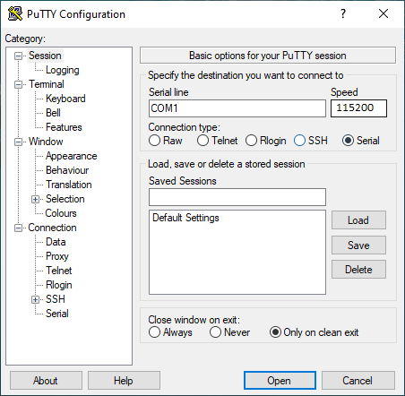
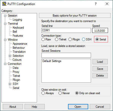
- In the Category navigation pane, click Session, and then in the Connection Type menu, click Serial.
- In the Category navigation pane, click Connection > Serial. The Options Controlling Local Serial Lines page displays.
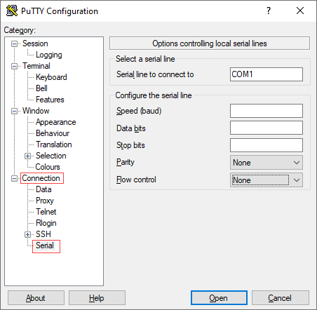
- In the Serial Line To Connect To field, enter the COM port to which your device is connected. The default COM port is COM1.

- In the Configure the Serial Line section, enter the following information.

- In the Speed (Baud) field, enter the digital transmission speed. For CSX1000 series appliances, the speed must be 115200 baud.
- In the Data bits field, enter the number of data bits used for each character. The recommended value is 8.
- In the Stop bits field, enter the number of bits to send at the end of every character. The recommended value is 1.
- In the Parity field, select None. This is the method of detecting errors in transmission.
- In the Flow Control field, select None. This is the method of preventing data overflow.
- Optionally, in the Category navigation menu, click Session, and then in the Saved Sessions field, enter a name to save the session settings.

- Click Save.
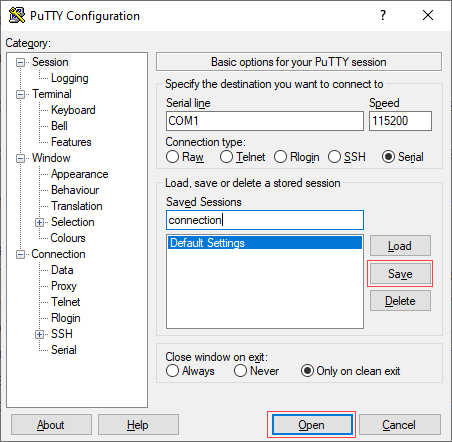
- To open the session, click Open.
- Log in to the appliance. Please consult Versa Networks technical support for default credentials.

Step 4: Connect a CSX1000 Series Appliance to a Network Management Console
You can deploy and manage a CSX1000 series appliance from a Director or Concerto node. While you can configure and manage the appliance using a management console, it is recommended that you do so from the Director or Concerto node.
You can perform monitoring and troubleshooting from the CLI on the CSX1000 series appliance'. To access the CLI, connect the appliance to the management console using a cable with an RJ-45 connector. Plug the RJ45 connector into the console port on the CSX1000 series appliance, and plug the other end of the cable into the console server or into a management console.